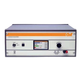
AR 1000T2G8B Service manual

Operating and
Service Manual
1000T2G8B
Model
10013175
Part Number
Serial Number
160 School House Road, Souderton, PA 18964 • 215-723-8181 • Fax 215-723-5688 • www.ar-worldwide.com


EC Declaration of Conformity
We; Amplifier Research
160 School House Road
Souderton, PA. 18964
declare that our product(s);
the Models 1000T1G2 series, 1000T2G8 series and 1000T8G18 series RF amplifiers
to which this declaration relates is in compliance with the requirements of the:
EEC EMC Directive (89/336/EEC) in accordance with Article 10 (2) of the directive, with the provision that
the user must install the equipment as directed by the “Instructions for European EMC Conformity” in the
Operating and Service Manual.
This product(s) is in compliance with the requirements of the Low Voltage Directive (72/23/EEC) in
accordance with safety standard IEC EN60950 (1995).
The CE marking is affixed on the device according to the EC Directives.
Donald R. Shepherd
President


Instructions for European EMC Conformity
WARNING
It is the responsibility of the user of this equipment to provide electromagnetic shielding, filtering and isolation
which is necessary for EMC compliance to Directive 89/336/EEC. The equipment must therefor be operated in a
shielded area which provides a sufficient level of attenuation to meet the radiated emissions and immunity
specifications. All AC, DC and Control lines connected to the equipment and entering or exiting the shielded
area must have sufficient isolation to meet the conducted emissions and immunity specifications. The following
minimum levels are suggested for use in accordance with the rated power of the equipment.
Rated Power Minimum shielding attenuation Minimum line isolation
100 watts 50 dB 50 dB
101 - 1000 watts 60 dB 60 dB
1001 - 10,000 watts 70 dB 70 dB
Since this equipment is designed to generate high levels of Radio Frequency energy, it is also essential that the
user read and follow the “Instructions for Safe Operation” in this manual. If other equipment is operated in the
shielded room it may be disturbed by the amplifier.
ACHTUNG
Der Benutzer dieses Gerätes ist dafür verantwortlich, daß die elektromagnetische Abschirmung und Filterung
gewährleistet ist, welche gemäß Richtlinie 89/336/EEC notwendig ist. Das Gerät muß deshalb in einem
geschirmten Raum betrieben werden, welcher eine ausreichenden Schirmung bietet, um die Emissions- und
Störfestigkeitsspezifkation einzuhalten. Alle Wechsel- und Gleichspannungsleitungen sowie Steuerleitungen,
die mit dem Gerät verbunden sind und in den geschirmten Raum von außen hereingeführt werden, müssen
ausreichend gefiltert sein, um die Emissionsspezifkation einzuhalten. Es werden folgenden Minimalwerte der
Schirmdämpfung und Filterung in den unterschiedlichen Leistungsklassen empfohlen.
Hochfrequenzleistung min. Schirmdämpfung min Filterdämpfung
100 Watt 50 dB 50 dB
101-1000 Watt 60 dB 60 dB
1001-10.000 Watt 70 dB 70 dB
Falls andere elektrische oder elektronische Geräte gleichzeitig mit dem Gerät betrieben werden, kann es zu
Beeinflussungen kommen. Da das Gerät zur Erzeugung von Hochfrequenzenergie dient ist es daher auch
unbedingt notwendig, daß der Benutzer die Sicherheitsvorschriften in der Bedienungsanleitung liest und einhält.
AVERTISSEMENT
Il est de la responsabilité de l'utilisateur de cet équipement d'assurer la protection électromagnétique, le filtrage
et l'isolation nécessaires, afin de se conformer à la directive 89/336/EEC concernant la C.E.M. Par conséquent,
cet équipement doit être mis en fonctionnement dans une enceinte d'atténuation suffisante pour satisfaire aux
spécifications d'émissivité et de susceptibilité. Toutes les alimentations alternatives, continues ainsi que les
liaisons de contrôle connectées à cet équipement, qui entrent ou sortent de cette enceinte doivent avoir une
isolation suffisante pour satisfaire aux spécifications concernant les émissions conduites et d'immunité. Pour une
utilisation conforme, les niveaux d'atténuation minimums suivants sont suggérés en fonction de la puissance de
sortie de l'équipement:
Puissance de sortie Atténuation minimum de l'enceinte Isolation minium de la ligne
100 Watts 50 dB 50 dB
101 à 1.000 Watts 60 dB 60 dB
1.001 à 10.000 Watts 70 dB 70 dB
Puisque cet équipement est destiné à générer de forts niveaux R.F., il est essentiel que l'utilisateur se conforme
aux instructions de sécurité indiquées dans ce manuel. Tout autre équipement en fonctionnement dans la cage de
Faraday peut-être perturbé par 1'amplificateur.


INSTRUCTIONS FOR SAFE OPERATION
BEFORE APPLYING POWER
Review this manual and become familiar with all safety
markings and instructions.
Verify that the equipment line voltage selection is
compatible with the main power source.
Protection provided by the equipment may be impaired if
used in a manner not specified by Amplifier Research.
INTENDED PURPOSES
This equipment is intended for general laboratory use in a
wide variety of industrial and scientific applications. It is
designed to be used in the process of generating, controlling,
and measuring high levels of electromagnetic Radio
Frequency (RF) energy. Therefore, the output of the amplifier
must be connected to an appropriate load such as an antenna
or field-generating device. It is the responsibility of the user to
assure that the device is operated in a location which will
control the radiated energy such that it will not cause injury
and will not violate regulatory levels of electromagnetic
interference.
HAZARDOUS RF VOLTAGES
The RF voltages on the center pin of the RF output connector
can be hazardous. The RF output connector should be
connected to a load before AC power is applied to the
amplifier. Do not come into contact with the center pin of the
RF output connector or accessories connected to it. Place the
equipment in a non-operating condition before disconnecting
or connecting the load to the RF output connector.
SAFETY GROUND
This equipment is provided with a protective earth terminal.
The main power source to the equipment must supply an
uninterrupted safety ground of sufficient size to the input
wiring terminals, power cord, or supplied power cord set. The
equipment MUST NOT BE USED if this protection is
impaired.
PHYSICAL DAMAGE
The RF amplifier should not be operated if there is physical
damage, missing hardware, or missing panels.
MAINTENANCE CAUTION
Adjustment, maintenance, or repair of the equipment must be
performed only by qualified personnel. Hazardous energy may
be present while protective covers are removed from the
equipment even if disconnected from the power source.
Contact may result in personal injury. Replacement fuses are
required to be of specific type and current rating.
SAFETY SYMBOLS
This symbol is marked on the equipment
when it is necessary for the user to refer to
the manual for important safety information.
Dangerous voltages are present. Use extreme
care.
CAUTION:The caution symbol denotes a
potential hazard. Attention must be given to
the statement to prevent damage, destruction,
or harm.
Indicates protective earth terminal.
RANGE OF ENVIRONMENTAL CONDITIONS
This equipment is designed to be safe under the following
environmental conditions:
Indoor use
Altitude up to 2000M
Temperature of 5°C to 40°C
Maximum relative humidity 80% for temperatures up to
31°C. Decreasing linearly to 50% at 40°C.
Main supply voltage fluctuations not to exceed ± 10% of
the nominal voltage or minimum and maximum
autoranging values.
Pollution degree 2: Normally non-conductive with
occasional condensation. While the equipment will not
cause hazardous condition over this environmental range,
its performance may vary.
COOLING AIR
Care should be exercised not to block the cooling air inlets or
outlets. Cooling air blockage can result in damage to the RF
amplifier or intermittent shut-downs.

ADDITIONAL WARNINGS & NOTES
WARNING:
This equipment operates at potentially lethal voltages. Only trained,
qualified personnel should operate, maintain, or service it.
CAUTION:
The information in this document was obtained from reliable sources and
was believed to be accurate at the time of publication. Since subsequent
modifications to the machine may have been made, use this information
only as a guide. Carefully compare the unit's actual configuration and
operation to the descriptions in this manual before you undertake to
operate, service, or modify this machine. Any variance or modification
should be noted, dated, and initialed in the discrepant part of all manuals
on hand for future reference. If you have technical or editorial comments
you wish to make to the manufacturer, please write them on photocopies
of the relevant sheets.
NOTE: The contents of this document are the property of the manufacturer and this document is delivered
on the express condition that it not be disclosed, reproduced in whole or in part, or used for
manufacture for anyone other than the manufacturer without its written consent, and that no right is
granted to disclose or so use any information in this document.


i
TABLE OF CONTENTS
TABLE OF CONTENTS ..................................................................................................I
1. DESCRIPTION AND SPECIFICATIONS.............................................................1
1.1 TWTA Description....................................................................................................1
1.2 Suggested Applications.............................................................................................1
1.3 Specifications ............................................................................................................1
1.4 Accessories................................................................................................................1
1.5 Test Data Sheet..........................................................................................................2
2. THEORY OF OPERATION....................................................................................5
2.1 Design of the Amplifier.............................................................................................5
2.2 Control Module .........................................................................................................5
2.3 Description of the RF Combiner Assembly...............................................................5
2.4 Description of the TWT Power Supplies...................................................................6
3. OPERATION.............................................................................................................7
3.1 Warnings and Cautions..............................................................................................7
3.2 Installation.................................................................................................................8
3.2.1 Unpacking ..............................................................................................................8
3.2.2 Mounting................................................................................................................8
3.2.3 Cooling Requirements............................................................................................8
3.2.4 AC Line Power Connections.................................................................................. 9
3.2.5 RF Connections......................................................................................................9
3.2.6 External Interlock Connector .................................................................................9
3.3 Front Panel Features................................................................................................10
3.4 Front Panel Display and Soft Keys .........................................................................12
3.5 Rear Panel Features.................................................................................................16
3.6 Initial Turn On and Warm-up Procedure.................................................................17
3.7 Remote IEEE-488 Operation...................................................................................18
3.8 TWTA General Considerations...............................................................................23
5. MAINTENANCE.....................................................................................................27
4.1 Safety Warning........................................................................................................27
4.2 Unauthorized Repairs..............................................................................................27
4.3 Preventive Maintenance ..........................................................................................27
4.4 Troubleshooting....................................................................................................... 29
4.5 Non-Repairable Modules......................................................................................... 29
5. TECHNICAL DOCUMENTATION .....................................................................31
5.1 Top Level Build Tree ..............................................................................................33
5.2 Schematics...............................................................................................................35
5.3 Block Diagram.........................................................................................................37
5.4 Parts Lists ................................................................................................................39
5.4.1 Parts List, HPA Logic and Control Module, A16485-000...................................40
5.4.2 Parts List, 3U Power Supply for TWT 5196, 1 Phase, A24801-501...................42
5.4.3 Parts List, Emergency Bypass Board, A24830-002 .............................................43
5.4.4 Parts List, HPA Interface Board (Plastic Fibers), A25444-000............................ 44
5.4.5 Parts List, 1000T Combiner VPC Interface A27444-001 ...................................47
5.4.6 Parts List, Combiner RF Components, 1000T SC, A27995-003 .........................50

Model 1000T2G8B
5.4.7 Parts List, 1000W TWTA SC Band Continuous, 208, A28002-304...................51
5.4.8 Parts List, RF Combiner Assy SC Band, A28005-004......................................... 52
5.4.9 Parts List, Control Unit, 1000T, 208VAC, 3-Phase, A28010-303.......................53
5.4.10 Parts List, 1000T S/C-Band P.S., A28012-000.................................................. 54
5.5 Recommended Spare Parts...................................................................................... 55
5.6 Sample Program for IEEE-488 Communication.....................................................56
FIGURES
3-1 - TWTA Front Panel Features....................................................................................10
3-2 - Front Panel Display Screens ....................................................................................12
3-3 - TWTA Rear Panel Features .....................................................................................16
TABLES
3-1 - Front Panel Features.................................................................................................11
3-2 - Rear Panel Features..................................................................................................17
3-3 - Catalog of IEEE-488 Commands.............................................................................18
3-4 - Catalog of Status Codes ...........................................................................................20
3-5 - Catalog of Fault Codes.............................................................................................20
3-6 - Catalog of System State Codes ................................................................................21
3-7 - Catalog of *STA?; Response Codes ........................................................................21
3-8 - Catalog of *STB?; Response Codes.........................................................................22
3-9. Catalog of Heater Auto Off Time Delay Codes .......................................................22
ii

Rev - 1
1. DESCRIPTION AND SPECIFICATIONS
This manual provides operating, interfacing and selected service information pertinent to Amplifier
Research Model 1000T2G8B Broadband Microwave Amplifier. The Model 1000T2G8B is a 1000 watt
SC-band traveling-wave tube amplifier (TWTA).
1.1 TWTA DESCRIPTION
The amplifier uses two traveling wave tubes (TWTs) power combined to provide rated power output over the
TWT amplifier's full bandwidth. Harmonic power is moderate at the amplifier output flange without filtering
by the use of this power combining approach. The amplifier is well suited for susceptibility and general
laboratory testing where instantaneous bandwidth, high gain and moderate or low harmonic levels are
required.
The amplifier is completely self-contained and packaged in a standard 19-inch rack cabinet provided with
lifting eyes and castors. The amplifier cabinet is approximately 63 inches high including castors and lifting
eyes, 22 inches wide at the base, and 33 inches deep at the base, excluding projecting rear-panel connectors.
Primary power is 190-255 volts, 50/60 Hz, three phase with ground (4 wire). Efficient switching power
supplies result in minimum power consumption. A fast regulation control loop and a high degree of filtering
ensure performance within specifications over a wide range of operating conditions. The amplifier is fully
enclosed, and the service panels of the amplifier are interlocked to reduce the likelihood of accidental contact
with high voltage.
1.2 SUGGESTED APPLICATIONS
RF Susceptibility testing
Antenna and component testing
Equipment calibration
General laboratory instrumentation
1.3 SPECIFICATIONS
Refer to the Amplifier Research Data Sheet on the following pages for detailed specifications.
1.4 ACCESSORIES
Amplifier Research offers a number of accessories for use with this amplifier including:
Directional coupler
Antenna
Flexible transmission line
Refer to a current Amplifier Research catalogue for Microwave Accessories.

Model 1000T2G8B
2 Rev -
1.5 TEST DATA SHEET
A Test Data Sheet for a specific unit is prepared at the time of manufacture and is included with the unit's
copy of this manual.

a switching mode power supply results in sig-
nificant weight reduction.
The rated power is developed by efficiently
power combining the outputs from two 535
watts (nominal) microwave tubes that are fac-
tory matched in gain and phase to offer mod-
erate harmonic levels without added filters.
Amplifier includes wheels, leveling feet and
lifting hooks.
The Model 1000T2G8B provides readily avail-
able RF power for a variety of applications in
Test and Measurement, (including EMC RF
susceptibility testing), Industrial and University
Research and Development, and Service appli-
cations. Unit is CE marked to comply with
EMC European Directive 89/336/EEC for op-
eration inside a shielded room.
Refer to the Model Configuration Chart for
alternative configurations.
The export classification for this equipment is
EAR99. These commodities, technology or
software are controlled for export in accord-
ance with the U.S. Export Administration Regu-
lations. Diversion contrary to U.S. law is pro-
hibited.
The Model 1000T2G8B is a self contained,
forced air cooled, broadband traveling wave
tube (TWT) microwave amplifier designed for
applications where instantaneous bandwidth,
high gain and high power output are required.
Reliable TWT subsystems provide a conserva-
tive 1000 watts minimum over most of the
frequency range at the amplifier output con-
nector. Stated power specifications are at fun-
damental frequency.
The amplifier's front panel digital display
shows forward and reflected output plus exten-
sive system status information accessed
through a series of menus via soft keys. Status
indicators include power on, warm-up,
standby, operate, faults, excess reflected power
warning and remote. Standard features in-
clude a built-in IEEE-488 (GPIB) interface,
0dBm input, VSWR protection, gain control, RF
output sample ports, plus monitoring of TWT
helix current, cathode voltage, collector volt-
age, heater current, heater voltage, baseplate
temperature and cabinet temperature. Modu-
lar design of the power supply and RF compo-
nents allow for easy access and repair. Use of
Features
Specifications
1000T2G8B
M1, M2, M3, M7–
M11
1000 Watts CW
2.5GHz–7.5GHz
AR RF/Microwave
Instrumentation
160 School House Rd
Souderton, PA 18964
215-723-8181
For an applications engi-
neer call:800.933.8181
www.arworld.us

POWER (fundamental), CW, @ OUTPUT
CONNECTOR:
Nominal: 1100 watts
Minimum: 900 watts minimum, 2.5–2.7GHz;
1000 watts minimum 2.7–7.5GHz.
Linear @ 1 dB Compression: 250 watts minimum
FLATNESS: ±8 dB maximum, equalized for ±3 dB
maximum at rated power
FREQUENCY RESPONSE: 2.5–7.5 GHz instantaneous-
ly
INPUT FOR RATED OUTPUT: 1.0 milliwatt maximum
GAIN (at maximum setting): 60 dB minimum
GAIN ADJUSTMENT (continuous range): 35 dB mini-
mum
INPUT IMPEDANCE: 50 ohms, VSWR 2.0:1 maximum
OUTPUT IMPEDANCE: 50 ohms, VSWR 2.5:1 typical
MISMATCH TOLERANCE: Output power foldback
protection at reflected power exceeding 200 watts. Will
operate without damage or oscillation with any magni-
tude and phase of source and load impedance. May
oscillate with unshielded open due to coupling to in-
put. Should not be tested with connector off.
MODULATION CAPABILITY: Will faithfully reproduce
AM, FM, or pulse modulation appearing on the input
signal. AM peak envelope power limited to specified
power.
NOISE POWER DENSITY: Minus 80 dBm/Hz
(maximum); Minus 90 dBm/Hz (typical)
HARMONIC DISTORTION: Minus 15 dBc maximum,
Minus 17 dBc typical
PRIMARY POWER: See Model Configuration
CONNECTORS:
RF input: Type N female
RF output: See Model Configuration
RF output sample ports (forward and reflected):
Type N female
GPIB: IEEE-488 female, rear
Interlock: DB-15 female, rear
COOLING: Forced air (self contained fans), air entry
and exit in rear.
WEIGHT (approximate): 295 kg (650 lb)
SIZE (WxHxD): 56 x 160 x 82.3 cm (22.1 x 63 x 32.4
in)
EXPORT CLASSIFICATION: EAR99
Page 2
Specifications
1000T2G8B
M1, M2, M3, M7–
M11
1000 Watts CW
2.5GHz–7.5GHz

Page 3
1000T2G8B
M1, M2, M3, M7–
M11
1000 Watts CW
2.5GHz–7.5GHz
Model Configurations
To order AR Products, call 215.723.8181. For an applications engineer call:800.933.8181. Direct to Service call: 215.723.0275 or
Approved for public release by AR RF/Microwave Instrumentation 072115
Model Number Primary Power RF Output
Connectors
RF input & output
sample ports
connector location
Features
1000T2G8B
190-255 VAC,
3 phase, delta
(4 wire)
50/60 Hz, 8.0
KVA max
Type
WRD250D30
waveguide
flange on
rear panel
rear panel –
1000T2G8BM1
360-435 VAC,
3 phase, WYE
(5 wire)
50/60 Hz, 8.0
KVA max
Type
WRD250D30
waveguide
flange on
rear panel
rear panel –
1000T2G8BM2
190-255 VAC,
3 phase, delta
(4 wire)
50/60 Hz,8.0
KVA max
2.5-4.0GHz,
WRD200D24
4-7.5GHz,
WRD350D24
waveguide
flange on
rear panel
rear panel
Frequency response
2.5-4.0GHz instantaneously,
4-7.5GHz instantaneously,
Power 900 watts minimum from 2.5-3
GHz and 7-7.5 GHz, 1000 watts
minimum from 3-7 GHz
1000T2G8BM3
360-435 VAC,
3 phase, WYE
(5 wire)
50/60 Hz, 8.0
KVA max
2.5-4.0GHz,
WRD200D24
4-7.5GHz,
WRD350D24
waveguide
flange on
rear panel
rear panel
Frequency response
2.5-4.0GHz instantaneously
4-7.5GHz instantaneously,
Power 900 watts minimum from 2.5-3
GHz and 7-7.5 GHz, 1000 watts
minimum from 3-7 GHz
1000T2G8BM4 See Individual Specification Sheet. Version offers 400 Hz primary power and a blanking input.
1000T2G8BM5 See Individual Specification Sheet. Version offers reduced harmonics using switched external
filters and other special features.
1000T2G8BM6 See Individual Specification Sheet. Version offers front panel connectors and other special fea-
tures.
1000T2G8BM7
190-255 VAC,
3 phase, delta
(4 wire)
50/60 Hz, 8.0
KVA max
Type
WRD250D30
waveguide
flange on
rear panel
front panel –
1000T2G8BM8 See Individual Specification Sheet.
1000T2G8BM9
190-255 VAC,
3 phase, delta
(4 wire)
50/60 Hz, 8.0
KVA max
Type
WRD250D30
waveguide
flange on
rear panel
rear panel
Mounted in EMC-shielded cabinet
providing >40 dB isolation.
Cabinet dimensions: 56 x 160 x 97.5
cm,
22.1 x 63 x 38.4 in.
NOTE: No penetrations through
shielded cabinet. AC & RF penetra-
tions to be made by end-user.
1000T2G8BM10
190-255 VAC,
3 phase, delta
(4 wire)
50/60 Hz, 8.0
KVA max
Type
WRD250D30
waveguide
flange on
rear panel
rear panel
Remote interface changed from IEEE-
488 to Ethernet. Supplied in four
separate 19” width rack-mountable
subassemblies and slides for rack
mounting; sizes 3U x 46cm (18.1”),
12U x 76.5cm (30.12”), (2) 3U x
61.2cm (24.1”).
1000T2G8BM11
360-435 VAC,
3 phase, WYE
(5 wire)
50/60 Hz, 8.0
KVA max
Type
WRD250D30
waveguide
flange on
rear panel
rear panel
Supplied in four separate 19” width
rack-mountable subassemblies and
slides for rack mounting; sizes 3U x
46cm (18.1”), 12U x 76.5cm
(30.12”), (2) 3U x 61.2cm (24.1”).


Rev - 5
2. THEORY OF OPERATION
2.1 DESIGN OF THE AMPLIFIER
The Model 1000T2G8B TWT amplifier consists of four principal subsystems. From top to bottom, these are
the control module (A28010-303), the RF combiner assembly (A28005-004), and the two TWT power
supplies (A28012-000). These will be discussed in greater detail below. The system is completed by a number
of cables that interconnect the subsystems, and by the rack assembly.
See the build tree in section 5.1 for information about how the parts lists are structured.
2.2 CONTROL MODULE
The control module houses the microprocessor control system (control head), the data steering assembly, a
three-output DC power supply, a 28 VDC power supply, and an AC contactor for removing the AC power
from the TWT power supplies when the control module’s AC power switch is turned off.
The control head consists of three boards: the display board (A25425-000) provides the user interface
(display, buttons, and rotary encoder); the CPU board (A25450-000) contains the CPU, bus management
hardware, DRAM, EPROMs, and static RAM; and the the datalink board (A22488-003) provides the I/O to
the amplifier system as well as the IEEE-488 communication bus for computer interfacing.
The control head is provided with its own power supply and, other than thru the interface bus, is electrically
isolated from the amplifier. Communication with the amplifier is via fiberoptic links. The single pair of links
on the control head fans out to three pairs of links in the data steering assembly (A21175-000). These links go
to interface boards in the RF combiner and in each of the two power supplies. The data is “steered” by an
address byte in the data stream from the microprocessor. To make the connections between various chassis
backpanels, the fiberoptic data is converted to twisted/shielded pairs by line driver/receiver pairs on the three
F/O to RS-485 adapter boards (A28008-000). In the RF combiner and in the power supplies, the signals are
converted back into fibers by means of the same boards.
2.3 DESCRIPTION OF THE RF COMBINER ASSEMBLY
The TWTA consists of two stages of RF amplification: a high-gain, 4 watt solid state driver amplifier
(E01611-000), and a power-combined pair of traveling-wave tube amplifiers (E01608-000).
The type N RF input connector is located on the rear panel. The RF input is fed to the input connector on the
solid state preamp with a built-in voltage-controlled variable attenuator which permits control of the
amplifier’s output power from the control module. The amp’s output is split by a 180° hybrid. Each of the
hybrid’s secondaries is connected to the RF input of a TWT. The TWTs’ outputs are connected by waveguide
to the input ports of a magic tee (waveguide 180° hybrid) (E01607-000). The magic tee’s sum port, the port
that collects all in-phase products, is terminated with a 500 watt waveguide load. The magic tee’s difference
port, the port that collects the out-of-phase products, is connected to the RF output.
The electrical length of the circuits between the splitter and the combiner must be matched (so that the 180°
out-of-phase relationship will prevail across the full bandwidth, permitting efficient combining). To achieve
this, phase-matched cable assemblies and adjustable line stretchers are used.
Since the fundamental frequencies are amplified 180° out of phase, the second harmonic products, which
represent significant power in the lower part of the band, are largely in phase, and are dumped in the sum

Model 1000T2G8B
6 Rev -
port. The residual harmonics are typically less than –20dBc, low enough in power that they can be further
reduced, as needed, by a reflective filter without harm to the TWTs.
A directional coupler is installed at the magic tee output for power metering, sample port and VSWR
protection for the tubes. A reflected power foldback circuit utilizing the reflected power port reduces the
system’s gain under conditions of high VSWR so that a gradual increase in reflected power will not result in a
VSWR fault.
The RF output is WRD-250 waveguide.
The control module monitors and controls the RF combiner assembly via the switcher-combiner interface
board (A27444-001). This board generates the analog voltage that controls the variable attenuator and has A-
to-D converters for metering the power levels.
The TWTs are mounted on cooling units (A28036-000). Each cooling unit contains a high density heat sink, a
400 Hz cooling fan, and a fan inverter that operates from the AC line.
2.4 DESCRIPTION OF THE TWT POWER SUPPLIES
The two TWT power supplies are housed in separate 19” chassis 3 rack units (5.25") high. Each power supply
chassis contains a TWT power supply assembly (A24801-501), an HPA interface board (A25444-000), as
well as an AC input line filter and a front panel circuit breaker. In addition, each chassis has a 400 Hz cooling
fan and a fan inverter (A23692-000).
The power supply assembly is of modular construction. Low voltage power for logic and control of the entire
power supply assembly is provided by the low voltage power supply module (A23687-001). Control logic
and TWT protection circuits are contained in the HPA logic and Control Assembly (A16485-000).
The Heater Power Supply Module (A10010-000) powers the TWT DC heater. Bias and pulse top voltage for
the TWT grid are provided by the Modulator Assembly (A21422-000).
The high voltage power supply consists of the following: the Power Factor Correction module (A23683-000)
converts line voltage to DC for the high voltage switching supply. Switching transistors are on the Power
Board Assembly (A16487-000), and switching is controlled by the PWM Board (A10017-517). The high
voltage transformer and rectifiers are contained in the Diode Cap Assembly (A21425-500). The high voltage
DC is filtered in the HV Filter Assembly (A21461-500).
Interconnects between the power supply modules are through a motherboard. It is installed in the power
supply finned heat sink. The Motherboard/heat sink assembly is A24823-000.
The cooling air is provided by the 400 Hz fan mounted on the rear panel inside the air outlet grill.
The HPA interface board permits the control module to control the power supply and monitor analog values
and fault status. Control is through the F/O to RS-485 board, which converts the electrical data from the
control module back to fibers to the HPA interface board.
This manual suits for next models
1
Table of contents
Other AR Amplifier manuals

AR
AR 10U1000 Service manual

AR
AR 6900TP2G4M10 Service manual

AR
AR 150/150AW1000 Series Service manual

AR
AR 200T26z5G40A Series Service manual

AR
AR 1000T8G18B Series Service manual

AR
AR 25U1000 Service manual

AR
AR 40S6G18A-L Service manual

AR
AR 1200A225 Service manual

AR
AR 750W1000B Series Service manual

AR
AR 200T4G8 Service manual
Popular Amplifier manuals by other brands

Advanced Amplifiers
Advanced Amplifiers AA-10K250M-150 instruction manual

AUSTRALIAN MONITOR
AUSTRALIAN MONITOR AMIS120P operating manual

Stageline
Stageline STA-250 instruction manual

Aragon
Aragon Aragon 28K user guide

World Video Sales
World Video Sales MicroImage Video Systems VDA124RM Operation manual

Axxess
Axxess TYTO-01 installation instructions