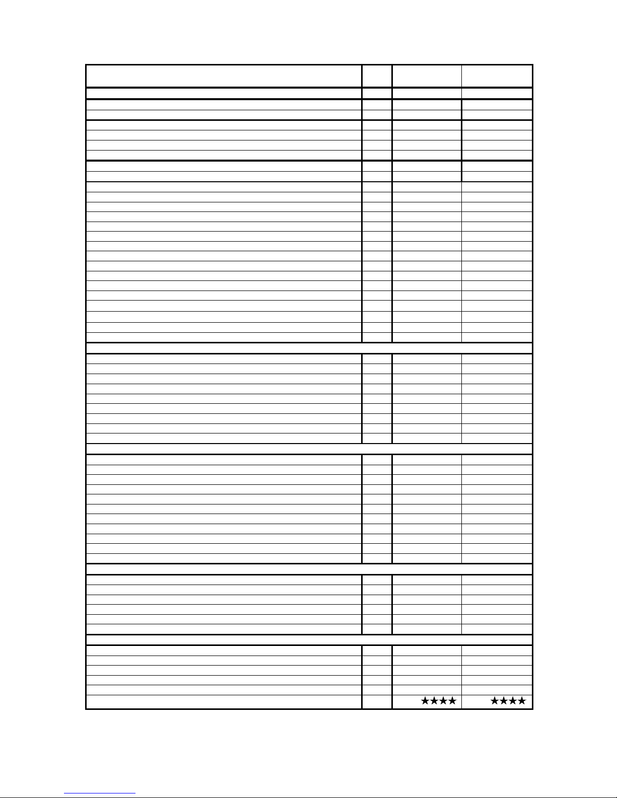
1.5 TECHNICAL DATA Size PIXEL 25 F C PIXEL 31 F C
Type C12-C32-C42-C52 C12-C32-C42-C52
Nominal Heat Input to net calorific value (Hi) referred (80 °C /60 °C) KW 25 31
Minimum Het Input to net calorific value (Hi) referred (80 °C /60 °C) KW 10,5 12,4
Nominal Heat Output (80 °C/60 °C) KW 24,4 30,2
Nominal Heat Output Condensing (50 °C/30 °C) KW 26,9 33,3
Minimum Heat Output (80 °C/60 °C) KW 10,1 11,9
Minimum Heat Output Condensing (50 °C/30 °C) KW 10,7 12,6
EfficiencyRendimento (80 °C/60 °C) % 97,6 97,5
Partial Load efficiency (30 % of Pn) % 108,7 107,9
Nominal Heat Input (Pn) gas flowrate Natural gas G20 (2E+) m3/h 2,643 3,278
Natural gas G25 (2ELL) m3/h 3,0745 3,812
LPG G30 (3+) kg/h 1,970 2,443
LPG G31 (3P) kg/h 1,941 2,406
Net gas pressure Natural gas G20 (2E+) mbar 20/25 20/25
Natural gas G25 (2ELL) mbar 20 20
GPL G30 (3+) mbar 29 29
LPG G31 (3P) mbar 37 37
Pn flue gas temperature (80 °C / 60 °C) °C 70 74
Pn flue gas temperature (50 °C / 30 °C) °C 47 51
CO2(G20) % 8 8
NOx (according par 6.2.2 of EN 483) mg/KWh 190 (classe 2) 190 (classe 2)
Losses of heat to the cheminey with burner ignited % 2,8 3,0
Losses of heat to the cheminey with burner not ignited % 0,2 0,1
Losses of heat to the cover (∆T = 50 °C) % 0,5 0,5
Flue gas flow rate Nm3/h 42,09 53,03
CENTRAL HEATING
C.H. Minimum Set point °C 35 35
C.H. Maximum Set point °C 90 90
Volume of water in the boiler l 1,2 1,2
Volume of water of the expansion vessel l 7,5 7,5
Pressure of the expansion vessel bar 0,7 0,7
Least pressure in the primary circuit bar 0,4 0,4
Maximum pressure in the primary circuit bar 3 3
Maximum content of heating water l 150 150
Available head at 1000 l/h of flow rate mbar 230 330
DOMESTICAL HOT WATER
Minimum set point °C 30 30
Maximum set point °C 60 60
Production continuous warm water (T = 25 °C) l/min 14 17,3
Production continuous warm water (T = 35 °C) l/min 10 12,4
Water Volume(T = 30 °C during the first 10 minutes) l 116,6 144,3
Minimum flow l/min 2,5 2,5
Maximum pressure bar 8 8
Minimum pressure bar 0,5 0,5
Voltage l ---- ----
Frequency V/Hz 230/50 230/50
Absorbed eletric power W 150 150
CONNECTION
Flow connection C.H. Inch 3/4" 3/4"
Flow connection D.H.W. Inch 1/2" 1/2"
Gas connection Inch 3/4" 3/4"
Height mm 720 720
Depth mm 300 300
Width mm 400 400
LENGHT OF FLUE GAS DUCTS
Ø 60 x 100 mm coaxial m 4 4
Ø 80 mm doubled m 30 30
Ø 60 mm doubled m ---- ----
Weight Kg 43 43
Degree of protection IP X4D X4D
CE certification 0068 0068
6