Architectural Acoustics IP-Six User manual

IP™-Six 2-Channel Power AmplifierUser Manual

2
Intended to alert the user to the presence of uninsulated “dangerous voltage” within the product’s
enclosure that may be of sufficient magnitude to constitute a risk of electric shock to persons.
Intended to alert the user of the presence of important operating and maintenance (servicing)
instructions in the literature accompanying the product.
CAUTION: Risk of electrical shock — DO NOT OPEN!
CAUTION: To reduce the risk of electric shock, do not remove cover. No user serviceable parts inside.
Refer servicing to qualified service personnel.
WARNING: To prevent electrical shock or fire hazard, this apparatus should not be exposed to rain or
moisture‚ and objects filled with liquids‚ such as vases‚ should not be placed on this apparatus. Before
using this apparatus‚ read the operating guide for further warnings.
Este símbolo tiene el propósito, de alertar al usuario de la presencia de “(voltaje) peligroso” sin
aislamiento dentro de la caja del producto y que puede tener una magnitud suficiente como para
constituir riesgo de descarga eléctrica.
Este símbolo tiene el propósito de alertar al usario de la presencia de instruccones importantes sobre la
operación y mantenimiento en la información que viene con el producto.
PRECAUCION: Riesgo de descarga eléctrica ¡NO ABRIR!
PRECAUCION: Para disminuír el riesgo de descarga eléctrica, no abra la cubierta. No hay piezas útiles
dentro. Deje todo mantenimiento en manos del personal técnico cualificado.
ADVERTENCIA: Para prevenir choque electrico o riesgo de incendios, este aparato no se debe exponer a
la lluvia o a la humedad. Los objetos llenos de liquidos, como los floreros, no se deben colocar encima
de este aparato. Antes de usar este aparato, lea la guia de funcionamiento para otras advertencias.
Ce symbole est utilisé dans ce manuel pour indiquer à l’utilisateur la présence d’une tension dangereuse
pouvant être d’amplitude suffisante pour constituer un risque de choc électrique.
Ce symbole est utilisé dans ce manuel pour indiquer à l’utilisateur qu’il ou qu’elle trouvera d’importantes
instructions concernant l’utilisation et l’entretien de l’appareil dans le paragraphe signalé.
ATTENTION: Risques de choc électrique — NE PAS OUVRIR!
ATTENTION: Afin de réduire le risque de choc électrique, ne pas enlever le couvercle. Il ne se trouve
à l’intérieur aucune pièce pouvant être reparée par l’utilisateur. Confiez I’entretien et la réparation de
l’appareil à un réparateur Peavey agréé.
AVIS: Dans le but de reduire les risques d'incendie ou de decharge electrique, cet appareil ne doit
pas etre expose a la pluie ou a l'humidite et aucun objet rempli de liquide, tel qu'un vase, ne doit
etre pose sur celui-ci. Avant d'utiliser de cet appareil, lisez attentivement le guide fonctionnant pour
avertissements supplémentaires.
Dieses Symbol soll den Anwender vor unisolierten gefährlichen Spannungen innerhalb des Gehäuses
warnen, die von Ausreichender Stärke sind, um einen elektrischen Schlag verursachen zu können.
Dieses Symbol soll den Benutzer auf wichtige Instruktionen in der Bedienungsanleitung aufmerksam
machen, die Handhabung und Wartung des Produkts betreffen.
VORSICHT: Risiko — Elektrischer Schlag! Nicht öffnen!
VORSICHT: Um das Risiko eines elektrischen Schlages zu vermeiden, nicht die Abdeckung enfernen.
Es befinden sich keine Teile darin, die vom Anwender repariert werden könnten. Reparaturen nur von
qualifiziertem Fachpersonal durchführen lassen.
WARNUNG: Um elektrischen Schlag oder Brandgefahr zu verhindern, sollte dieser Apparat nicht
Regen oder Feuchtigkeit ausgesetzt werden und Gegenstände mit Flüssigkeiten gefuellt, wie Vasen,
nicht auf diesen Apparat gesetzt werden. Bevor dieser Apparat verwendet wird, lesen Sie bitte den
Funktionsführer für weitere Warnungen.

3
IMPORTANT SAFETY INSTRUCTIONS
WARNING: When using electrical products, basic cautions should always be followed, including the following:
1. Read these instructions.
2. Keep these instructions.
3. Heed all warnings.
4. Follow all instructions.
5. Do not use this apparatus near water.
6. Clean only with a dry cloth.
7. Do not block any of the ventilation openings. Install in accordance with manufacturer’s instructions.
8. Do not install near any heat sources such as radiators, heat registers, stoves or other apparatus (including amplifiers)
that produce heat.
9. Do not defeat the safety purpose of the polarized or grounding-type plug. A polarized plug has two blades with one
wider than the other. A grounding type plug has two blades and a third grounding plug. The wide blade or third prong is
provided for your safety. If the provided plug does not fit into your outlet, consult an electrician for replacement of the
obsolete outlet.
10. Protect the power cord from being walked on or pinched, particularly at plugs, convenience receptacles, and the point
they exit from the apparatus.
11. Only use attachments/accessories provided by the manufacturer.
12. Use only with a cart, stand, tripod, bracket, or table specified by the manufacturer, or sold with the apparatus. When a
cart is used, use caution when moving the cart/apparatus combination to avoid injury from tip-over.
13. Unplug this apparatus during lightning storms or when unused for long periods of time.
14. Refer all servicing to qualified service personnel. Servicing is required when the apparatus has been damaged in any
way, such as power-supply cord or plug is damaged, liquid has been spilled or objects have fallen into the apparatus,
the apparatus has been exposed to rain or moisture, does not operate normally, or has been dropped.
15. Never break off the ground pin. Write for our free booklet “Shock Hazard and Grounding.” Connect only to a power
supply of the type marked on the unit adjacent to the power supply cord.
16. If this product is to be mounted in an equipment rack, rear support should be provided.
17. Note for UK only: If the colors of the wires in the mains lead of this unit do not correspond with the terminals in your
plug‚ proceed as follows:
a) The wire that is colored green and yellow must be connected to the terminal that is marked by the letter E‚ the earth
symbol‚ colored green or colored green and yellow.
b) The wire that is colored blue must be connected to the terminal that is marked with the letter N or the color black.
c) The wire that is colored brown must be connected to the terminal that is marked with the letter L or the color red.
18. This electrical apparatus should not be exposed to dripping or splashing and care should be taken not to place objects
containing liquids, such as vases, upon the apparatus.
19. Exposure to extremely high noise levels may cause a permanent hearing loss. Individuals vary considerably in suscep-
tibility to noise-induced hearing loss, but nearly everyone will lose some hearing if exposed to sufficiently intense noise
for a sufficient time. The U.S. Government’s Occupational Safety and Health Administration (OSHA) has specified the
following permissible noise level exposures:
Duration Per Day In Hours Sound Level dBA, Slow Response
8 90
6 92
4 95
3 97
2 100
1 1⁄2 102
1 105
1⁄2 110
1⁄4 or less 115
According to OSHA, any exposure in excess of the above permissible limits could result in some hearing loss. Ear plugs or protectors to
the ear canals or over the ears must be worn when operating this amplification system in order to prevent a permanent hearing loss, if
exposure is in excess of the limits as set forth above. To ensure against potentially dangerous exposure to high sound pressure levels, it is
recommended that all persons exposed to equipment capable of producing high sound pressure levels such as this amplification system be
protected by hearing protectors while this unit is in operation.
SAVE THESE INSTRUCTIONS!

4
WICHTIGE SICHERHEITSHINWEISE
ACHTUNG: Beim Einsatz von Elektrogeräten müssen u.a. grundlegende Vorsichtsmaßnahmen befolgt werden:
1. Lesen Sie sich diese Anweisungen durch.
2. Bewahren Sie diese Anweisungen auf.
3. Beachten Sie alle Warnungen.
4. Befolgen Sie alle Anweisungen.
5. Setzen Sie dieses Gerät nicht in der Nähe von Wasser ein.
6. Reinigen Sie es nur mit einem trockenen Tuch.
7. Blockieren Sie keine der Lüftungsöffnungen. Führen Sie die Installation gemäß den Anweisungen des Herstellers durch.
8. Installieren Sie das Gerät nicht neben Wärmequellen wie Heizungen, Heizgeräten, Öfen oder anderen Geräten (auch Verstärkern),
die Wärme erzeugen.
9. Beeinträchtigen Sie nicht die Sicherheitswirkung des gepolten Steckers bzw. des Erdungssteckers. Ein gepolter Stecker weist
zwei Stifte auf, von denen einer breiter ist als der andere. Ein Erdungsstecker weist zwei Stifte und einen dritten Erdungsstift auf.
Der breite Stift bzw. der dritte Stift dient Ihrer Sicherheit. Sollte der beiliegende Stecker nicht in Ihre Steckdose passen, wenden
Sie sich bitte an einen Elektriker, um die ungeeignete Steckdose austauschen zu lassen.
10. Schützen Sie das Netzkabel, sodass niemand darauf tritt oder es geknickt wird, insbesondere an Steckern oder Buchsen und
ihren Austrittsstellen aus dem Gerät.
11. Verwenden Sie nur die vom Hersteller erhältlichen Zubehörgeräte oder Zubehörteile.
12. Verwenden Sie nur einen Wagen, Stativ, Dreifuß, Träger oder Tisch, der den Angaben des Herstellers entspricht oder zusammen
mit dem Gerät verkauft wurde. Wird ein Wagen verwendet, bewegen Sie den Wagen mit dem darauf befindlichen Gerät besonders
vorsichtig, damit er nicht umkippt und möglicherweise jemand verletzt wird.
13. Trennen Sie das Gerät während eines Gewitters oder während längerer Zeiträume, in denen es nicht benutzt wird, von der
Stromversorgung.
14. Lassen Sie sämtliche Wartungsarbeiten von qualifizierten Kundendiensttechnikern durchführen. Eine Wartung ist erforderlich,
wenn das Gerät in irgendeiner Art beschädigt wurde, etwa wenn das Netzkabel oder der Netzstecker beschädigt wurden,
Flüssigkeit oder Gegenstände in das Gerät gelangt sind, das Gerät Regen oder Feuchtigkeit ausgesetzt wurde, nicht normal
arbeitet oder heruntergefallen ist.
15. Der Erdungsstift darf nie entfernt werden. Auf Wunsch senden wir Ihnen gerne unsere kostenlose Broschüre „Shock Hazard and
Grounding“ (Gefahr durch elektrischen Schlag und Erdung) zu. Schließen Sie nur an die Stromversorgung der Art an, die am
Gerät neben dem Netzkabel angegeben ist.
16. Wenn dieses Produkt in ein Geräte-Rack eingebaut werden soll, muss eine Versorgung über die Rückseite eingerichtet werden.
17. Hinweis – Nur für Großbritannien: Sollte die Farbe der Drähte in der Netzleitung dieses Geräts nicht mit den Klemmen in Ihrem
Stecker übereinstimmen, gehen Sie folgendermaßen vor:
a) Der grün-gelbe Draht muss an die mit E (Symbol für Erde) markierte bzw. grüne oder grün-gelbe Klemme angeschlossen
werden.
b) Der blaue Draht muss an die mit N markierte bzw. schwarze Klemme angeschlossen werden.
c) Der braune Draht muss an die mit L markierte bzw. rote Klemme angeschlossen werden.
18. Dieses Gerät darf nicht ungeschützt Wassertropfen und Wasserspritzern ausgesetzt werden und es muss darauf geachtet
werden, dass keine mit Flüssigkeiten gefüllte Gegenstände, wie z. B. Blumenvasen, auf dem Gerät abgestellt werden.
19. Belastung durch extrem hohe Lärmpegel kann zu dauerhaftem Gehörverlust führen. Die Anfälligkeit für durch Lärm bedingten
Gehörverlust ist von Mensch zu Mensch verschieden, das Gehör wird jedoch bei jedem in gewissem Maße geschädigt, der über
einen bestimmten Zeitraum ausreichend starkem Lärm ausgesetzt ist. Die US-Arbeitsschutzbehörde (Occupational and Health
Administration, OSHA) hat die folgenden zulässigen Pegel für Lärmbelastung festgelegt:
Dauer pro Tag in Stunden Geräuschpegel dBA, langsame Reaktion
8 90
6 92
4 95
3 97
2 100
1 1⁄2 102
1 105
1⁄2 110
1⁄4 oder weniger 115
Laut OSHA kann jede Belastung über den obenstehenden zulässigen Grenzwerten zu einem gewissen Gehörverlust führen. Sollte
die Belastung die obenstehenden Grenzwerte übersteigen, müssen beim Betrieb dieses Verstärkungssystems Ohrenstopfen oder
Schutzvorrichtungen im Gehörgang oder über den Ohren getragen werden, um einen dauerhaften Gehörverlust zu verhindern. Um sich vor
einer möglicherweise gefährlichen Belastung durch hohe Schalldruckpegel zu schützen, wird allen Personen empfohlen, die mit Geräten
arbeiten, die wie dieses Verstärkungssystem hohe Schalldruckpegel erzeugen können, beim Betrieb dieses Geräts einen Gehörschutz zu tra-
gen.
BEWAHREN SIE DIESE SICHERHEITSHINWEISE AUF!

5
INSTRUCTIONS IMPORTANTES DE SECURITE
ATTENTION: L’utilisation de tout appareil électrique doit être soumise aux precautions d’usage incluant:
1. Lire ces instructions.
2. Gardez ce manuel pour de futures références.
3. Prétez attention aux messages de précautions de ce manuel.
4. Suivez ces instructions.
5. N’utilisez pas cette unité proche de plans d’eau.
6. N’utilisez qu’un tissu sec pour le nettoyage de votre unité.
7. N’obstruez pas les systèmes de refroidissement de votre unité et installez votre unité en fonction des instructions
de ce manuel.
8. Ne positionnez pas votre unité à proximité de toute source de chaleur.
9. Connectez toujours votre unité sur une alimentation munie de prise de terre utilisant le cordon d’alimentation
fourni.
10. Protégez les connecteurs de votre unité et positionnez les cablages pour éviter toutes déconnexions accidentelles.
11. N’utilisez que des fixations approuvées par le fabriquant.
12. Lors de l’utilsation sur pied ou pole de support, assurez dans le cas de déplacement de l’ensemble enceinte/
support de prévenir tout basculement intempestif de celui-ci.
13. Il est conseillé de déconnecter du secteur votre unité en cas d’orage ou de durée prolongée sans utilisation.
14. Seul un technicien agréé par le fabriquant est à même de réparer/contrôler votre unité. Celle-ci doit être contrôlée si
elle a subit des dommages de manipulation, d’utilisation ou de stockage (humidité,…).
15. Ne déconnectez jamais la prise de terre de votre unité.
16. Si votre unité est destinée a etre montée en rack, des supports arriere doivent etre utilises.
17. Note pour les Royaumes-Unis: Si les couleurs de connecteurs du cable d’alimentation ne correspond pas au guide
de la prise secteur, procédez comme suit:
a) Le connecteur vert et jaune doit être connectrer au terminal noté E, indiquant la prise de terre ou correspondant
aux couleurs verte ou verte et jaune du guide.
b) Le connecteur Bleu doit être connectrer au terminal noté N, correspondnat à la couleur noire du guide.
c) Le connecteur marron doit être connectrer au terminal noté L, correspondant à la couleur rouge du guide.
18. Cet équipement électrique ne doit en aucun cas être en contact avec un quelconque liquide et aucun objet
contenant un liquide, vase ou autre ne devrait être posé sur celui-ci.
19. Une exposition à de hauts niveaux sonores peut conduire à des dommages de l’écoute irréversibles. La suscep-
tibilité au bruit varie considérablement d’un individu à l’autre, mais une large majorité de la population expériencera
une perte de l’écoute après une exposition à une forte puissance sonore pour une durée prolongée. L’organisme de
la santé américaine (OSHA) a produit le guide ci-dessous en rapport à la perte occasionnée:
Durée par Jour (heures) Niveau sonore moyen (dBA)
8 90
6 92
4 95
3 97
2 100
1 1⁄2 102
1 105
1⁄2 110
1⁄4 ou inférieur 115
D’après les études menées par le OSHA, toute exposition au delà des limites décrites ce-dessus entrainera des pertes de l’écoute chez la
plupart des sujets. Le port de système de protection (casque, oreilette de filtrage,…) doit être observé lors de l’opération cette unité ou des
dommages irréversibles peuvent être occasionnés. Le port de ces systèmes doit être observé par toutes personnes susceptibles d’être expo-
sées à des conditions au delà des limites décrites ci-dessus.
GARDEZ CES INSTRUCTIONS!

6
INSTRUCCIONES IMPORTANTES PARA SU SEGURIDAD
CUIDADO: Cuando use productos electrónicos, debe tomar precauciones básicas, incluyendo las siguientes:
1. Lea estas instrucciones.
2. Guarde estas instrucciones.
3. Haga caso de todos los consejos.
4. Siga todas las instrucciones.
5. No usar este aparato cerca del agua.
6. Limpiar solamente con una tela seca.
7. No bloquear ninguna de las salidas de ventilación. Instalar de acuerdo a las instrucciones del fabricante.
8. No instalar cerca de ninguna fuente de calor como radiadores, estufas, hornos u otros aparatos (incluyendo amplificadores)
que produzcan calor.
9. No retire la patilla protectora del enchufe polarizado o de tipo “a Tierra”. Un enchufe polarizado tiene dos puntas, una de
ellas más ancha que la otra. Un enchufe de tipo “a Tierra” tiene dos puntas y una tercera “a Tierra”. La punta ancha (la
tercera ) se proporciona para su seguridad. Si el enchufe proporcionado no encaja en su enchufe de red, consulte a un
electricista para que reemplaze su enchufe obsoleto.
10. Proteja el cable de alimentación para que no sea pisado o pinchado, particularmente en los enchufes, huecos, y los puntos
que salen del aparato.
11. Usar solamente añadidos/accesorios proporcionados por el fabricante.
12. Usar solamente un carro, pie, trípode, o soporte especificado por el fabricante, o vendido junto al aparato. Cuando se use
un carro, tenga cuidado al mover el conjunto carro/aparato para evitar que se dañe en un vuelco. No suspenda esta caja de
ninguna manera.
13. Desenchufe este aparato durante tormentas o cuando no sea usado durante largos periodos de tiempo.
14. Para cualquier reparación, acuda a personal de servicio cualificado. Se requieren reparaciones cuando el aparato ha sido
dañado de alguna manera, como cuando el cable de alimentación o el enchufe se han dañado, algún líquido ha sido
derramado o algún objeto ha caído dentro del aparato, el aparato ha sido expuesto a la lluvia o la humedad, no funciona de
manera normal, o ha sufrido una caída.
15. Nunca retire la patilla de Tierra.Escríbanos para obtener nuestro folleto gratuito “Shock Hazard and Grounding” (“Peligro
de Electrocución y Toma a Tierra”). Conecte el aparato sólo a una fuente de alimentación del tipo marcado al lado del cable
de alimentación.
16. Si este producto va a ser enracado con más equipo, use algún tipo de apoyo trasero.
17. Nota para el Reino Unido solamente: Si los colores de los cables en el enchufe principal de esta unidad no corresponden
con los terminales en su enchufe‚ proceda de la siguiente manera:
a) El cable de color verde y azul debe ser conectado al terminal que está marcado con la letra E‚ el símbolo de Tierra
(earth)‚ coloreado en verde o en verde y amarillo.
b) El cable coloreado en azul debe ser conectado al terminal que está marcado con la letra N o el color negro.
c) El cable coloreado en marrón debe ser conectado al terminal que está marcado con la letra L o el color rojo.
18. Este aparato eléctrico no debe ser sometido a ningún tipo de goteo o salpicadura y se debe tener cuidado para no poner
objetos que contengan líquidos, como vasos, sobre el aparato.
19. La exposición a altos niveles de ruido puede causar una pérdida permanente en la audición. La susceptibilidad a la pérdida
de audición provocada por el ruido varía según la persona, pero casi todo el mundo perderá algo de audición si se expone
a un nivel de ruido suficientemante intenso durante un tiempo determinado. El Departamento para la Salud y para la
Seguridad del Gobierno de los Estados Unidos (OSHA) ha especificado las siguientes exposiciones al ruido permisibles:
Duración por Día en Horas Nivel de Sonido dBA, Respuesta Lenta
8 90
6 92
4 95
3 97
2 100
1 1⁄2 102
1 105
1⁄2 110
1⁄4 o menos 115
De acuerdo al OSHA, cualquier exposición que exceda los límites arriba indicados puede producir algún tipo de pérdida en la audición.
Protectores para los canales auditivos o tapones para los oídos deben ser usados cuando se opere con este sistema de sonido para preve-
nir una pérdida permanente en la audición, si la exposición excede los límites indicados más arriba. Para protegerse de una exposición a
altos niveles de sonido potencialmente peligrosa, se recomienda que todas las personas expuestas a equipamiento capaz de producir altos
niveles de presión sonora, tales como este sistema de amplificación, se encuentren protegidas por protectores auditivos mientras esta uni-
dad esté operando.
GUARDE ESTAS INSTRUCCIONES!

7
IMPORTANT PRECAUTIONS
This symbol is used to alert the user to the
presence of important operating and maintenance
(servicing) instructions in the literature
accompanying the product.
This symbol is used to alert the user to the
presence of “dangerous voltage” within the
product enclosure that be of sufficient magnitude
to constitute a risk of electric shock to persons.
CAUTION: Risk of electrical shock - DO NOT OPEN!
CAUTION: To reduce the risk of electric shock, do not remove
cover. There are no user serviceable parts inside. Refer
servicing to qualified service personnel.
WARNING: To prevent electrical shock or fire hazard, do not
expose this appliance to rain or moisture. Before using this
appliance, read the operating guide for further warnings.
1. Save the carton and packing material even if the
equipment has arrived in good condition. Should
you ever need to ship the unit, use only the original
factory packing.
2. Read all operating instructions in this manual and
on the back of the unit. Retain all instructions for
future reference.
3. Follow all instructions printed on unit chassis for
proper operation.
4. Do not spill water or other liquids into or on the unit,
or operate the unit near water, i.e., a bathtub, sink,
swimming pool, wet basement, etc.
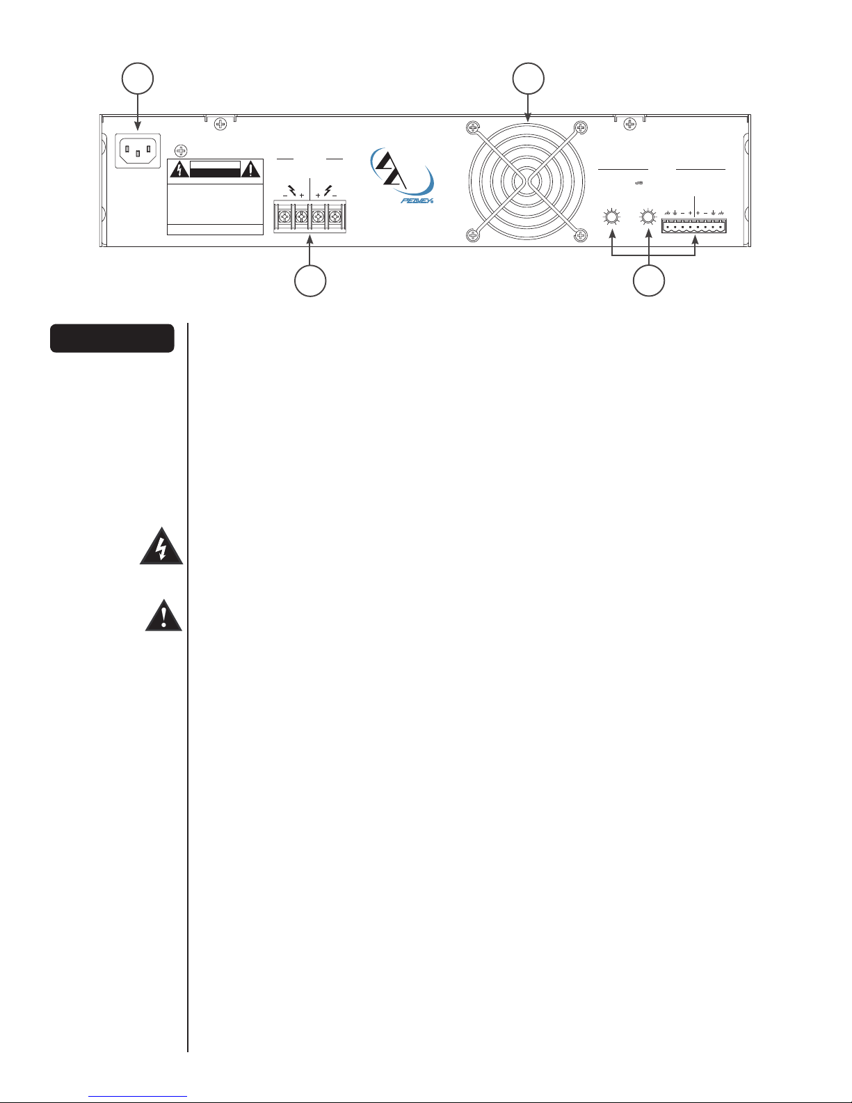
5. Connect only to a power supply of the type marked
on the unit adjacent to the power supply cord
connector. Damage caused by connection to
improper AC voltage is not covered by any
warranty.
6. Power supply cords should be handled carefully.
Never walk or place equipment on power supply
cords. Periodically check cords for cuts or signs of
stress, especially at the plug and the point where
the cord exits the unit.
7. Always operate the unit with the AC ground wire
connected to the electrical system ground. Never
break off the ground pin on the power supply cord.
For more information on grounding, write for our
free booklet Shock Hazard and Grounding.
8. Have gain controls on amplifiers turned down during
power-up to prevent speaker damage if there are
high signal levels at the inputs.
9. Power down and disconnect units from mains
voltage before making connections.
10. Disconnect unit from power supply before cleaning.
Metal parts can be cleaned with a damp rag.
11. This product should not be used near stoves, heat
registers, radiators, or other heat producing
devices.
12. Do not block the fan intake. This product should be
located so that its position does not interfere with
its proper ventilation. It should not be placed flat
against a wall or placed in a built-in enclosure or
rack that will impede the flow of cooling air.
13. The user should not attempt to service this
equipment. Do not remove the cover. All service
work should be performed by a qualified service
technician.
14. Do not drive the inputs with a signal level greater
than that required to drive equipment to full
output. Peavey Electronics is not responsible for
damage to loudspeakers for any reason.
15. Do not ground any + (“hot”) terminal. Never connect
a + (“hot”) output to ground or to another + (“hot”)
output!
16. The user should not attempt to service this
equipment. Equipment should be serviced by
qualified service personnel when:
A. The power supply cord or the plug has been
damaged;
B. Anything has fallen, or been spilled into the
equipment;
C. The equipment has been exposed to rain;
D. The equipment does not appear to operate normally,
or exhibits a marked change in performance;
E. The equipment has been dropped, or the enclosure
damaged.
17. If you need set-up or operation assistance for
this product, please call Architectural Acoustics
Customer Service, Tech Service or your local
authorized dealer.

8
IP™-Six Power Amplifier
Congratulations on your purchase of a Peavey Architectural Acoustics IP-Six power amplifier. Please
read this manual carefully (especially the “Important Precautions” section located inside the front
cover) as it contains information vital to the safe operation of the amplifier. Also, please fill out and
return the enclosed product registration card.
IP-Six amplifiers are ruggedly built from high quality components and feature comprehensive
protection circuits to protect your amplifier in the real world.
If you need setup or operation assistance for this product, please call Architectural Acoustics
Customer Service Tech Service or your local authorized dealer. We appreciate suggestions that may
help us improve our products or service.
Unpacking
Inspect the amplifier during unpacking. If you find any damage, notify your dealer immediately. Only
the consignee may institute a claim with the carrier for damage incurred during shipping. Be sure
to save the carton and all packing materials. Should you ever need to ship the unit back to Peavey
Electronics, one of its service centers or the dealer, use only the original factory packaging.
Mounting
IP-Six amplifiers are two rack space units of 13.5" (343 mm) depth that mount in a standard 19" rack.
On all amplifiers, four front-panel mounting holes are provided. Rear-mounting ears are also provided
on all amplifiers for additional support. Distance from the back of the front-rack ear to the center of
the rear-mounting ear holes is 13 1/8" (333 mm).
To set the amplifier up for basic usage:
1. Rack mount the amplifier in the location where it is to be used, remembering to allow for
adequate access and cooling space. For more information, see the sections on Installation,
Mounting and Cooling Requirements.
2. Make input connections to the plugable terminal blocks on the input module. Use the
proper connections for stereo, parallel, bridged mono and grounding configuration. See the
sections on Signal Mode Configuration and Input Module Connections for more information.
3. Connect speakers to the output barrier strip. Be sure to make the correct output
connections for stereo, parallel or bridged mono configuration. See the section on Speaker
Output Connections for more information.
4. Make power connections, allowing for proper current draw. See the section on AC Mains
Circuit Size Requirements for more information.
5. Turn the front panel AC switch to ON, and bring up the back-panel gain attenuators to the
desired levels.
ENGLISH
Introduction
Installation and
Mounting

9
POWER
INDUSTRIAL POWER AMPLIFIER
CLIP
STATUS
Ch A Ch B
- S I X
by
TM
RCHITECTURAL
COUSTICS
ON
Front Panel (1) Rack Mounting Ears
Two mounting holes are provided on each front mounting ear.
(2) AC Power Switch/Circuit Breaker
A power switch-and-circuit breaker combination switch is on the front panel. With the switch
pushed toward the up position, the amplifier is ON. If the switch/breaker continues to trip, the
amplifier needs servicing. Do not continue to reset, as severe internal damage and safety hazards
could occur!
(3) STATUS LED
Each channel has a Status LED which indicates that the corresponding channel is active and has
its speaker protection relays engaged.
(4) CLIP LED
Each channel has a Clip Limiting LED. This LED illuminates at the clipping point and indicates
that internal circuitry is reducing amplifier gain to allow full power. See the section on Protection
Features for more information.
11
11
2
4
3

10
(1) Input Connector
The IP™-Six has a plugable input connector and individual channel rotary attenuators. Gain/input
sensitivity is factory set for an overall gain of x40. Connections at the input connector permit the
audio signal ground to be connected or lifted from the chassis ground. See the sections on Input
Module Connections and Removing or Replacing a Module for more information.
(2) Output Barrier Strip
A barrier strip is provided for connection of loudspeakers with bare wire or spade-lug connectors.
(3) IEC Power Connector
A standard IEC power connector is located at the upper left corner of the amplifier back panel. An AC
mains cord with the appropriate AC plug for the intended operating voltage is included.
(4) Fan Grille
A continuously variable speed DC fan supplies cool air into the amplifier. Do not block this air intake!
The fan operates only when the amplifier heat sinks require cooling.
Rear Panel
120VAC ~ 60Hz
550 Watts
A Product of Peavey Electronics Corp.
711 A St.
Meridian, MS 39301
Designed & Built in the U.S.A.
Inputs
Level ( )
-80 0-80 0
Balanced Line Level
400W/Ch. @ 2 Ohms
Outputs
Ch ACh BCh ACh B
Ch ACh B
by
TM
RCHITECTURAL
COUSTICS
AVIS: RISQUE DE CHOC ÉLECTRIQUE-NE PAS OUVRIR
CAUTION
RISK OF ELECTRIC SHOCK
DO NOT OPEN
WARNING: TO REDUCE THE RISK OF FIRE OR
ELECTRIC SHOCK, THIS APPARATUS SHOULD NOT BE
EXPOSED TO RAIN OR MOISTURE AND OBJECTS FILLED
WITH LIQUIDS, SUCH AS VASES, SHOULD NOT BE
PLACED ON THIS APPARATUS.
AVIS: DANS LE BUT DE REDUIRE LES RISQUES
D’INCENDIE OU DE DECHARGE ELECTRIQUE, CET
APPREIL NE DOIT PAS ETRE EXPOSE A LA PLUIE OU A
L’HUMIDITE ET AUCUN OBJET REMPLI DE LIQUIDE, TEL
QU’UN VASE, NE DOIT ETRE POSE SUR CELUI-CI.
MOUNT IN RACK ONLY.
INSTALLER SUR SUPPORT DE MONTAGE SEULEMENT.
3
1
4
2

11
AC Mains Circuit Size Requirements
Power requirements for the IP™-Six amplifier are rated at “idle”, 1/8 power (“typical” music
conditions), 1/3 power and maximum rated power. The maximum power current draw rating is limited
by the amplifier’s circuit breaker. Consult the specification sheet for the current that each amplifier will
demand. AC mains voltage must be the same as that indicated on the back of the amplifier. Damage
caused by connecting the amplifier to improper AC voltage is not covered by any warranty.
NOTE: Always turn off and disconnect the amplifier from the mains voltage before making
audio connections. As an extra precaution, turn down the input attenuators while powering
up.
Cooling Requirements
IP-Six amplifiers use a forced-air cooling system to maintain a consistently low operating temperature.
Air is drawn by a continuously variable speed fan mounted on the back panel and exhausts through
slots on the front panel. The fan will remain inactive until the internal operating temperature rises
above 45°C. Make sure that there is enough space around the back of the amplifier to allow air to
enter.
NOTE: If the amplifier is rack mounted, do not use doors or covers on the front or back
without pressurizing the back of the rack. Regardless of the type of rack you are using, make
sure that heated air can escape freely, and that there is no resistance to the intake of cool air
through the back grille. Intake and exhaust air must flow without resistance.
Hibernation
The IP-Six features Hibernation circuitry. Current draw and thermal emissions are at a minimum with
the absence of an input signal. Once a signal is present, Hibernation instantly restores the amplifier
to normal. Current draw specifications while Hibernation is active are included in specifications under
“Idle Current Draw.”
Thermal Emissions
The system installer or designer should specify system cooling needs. Refer to the specifications
appendix at the back of this manual for specific thermal emissions figures.
Input Module Connections
The input connector accepts balanced and unbalanced audio signals. For use with an unbalanced
source, tie the inverting (-) input to ground by installing a jumper to the signal ground connection. If
the inverting input is left floating, a 6 dB loss in gain will result.
Operation

12
Signal Mode Configuration
The IP™-Six amplifier is configured for Two-Channel (Stereo), Bridged Mode or Parallel Mode
operation at the input connector.
To send the same signal to both channels (Parallel Mode), connect the input signal to channel A
via the input connector. Run jumpers from the positive and negative terminals of channel A’s input
connector to the respective terminals of channel B. Both channels then share channel A’s input signal,
but will operate independently. Speakers are connected as in two-channel (stereo) mode.
Bridged Mode converts the amplifier into a single-channel unit with a power rating equal to the sum of
both channel’s power ratings, and at a load rating of twice that of the single-channel rating. In Bridged
Mode, the channels operate at opposite polarity of each other so that one channel “pushes” and
the other “pulls” equally. Signal is connected to the input connector with one jumper connecting the
positive (+) terminal of input A to the negative (-) terminal of input B, and another jumper connecting
the negative (-) terminal of input A to the positive (+) terminal of input B. Both channel attenuators (A
and B) are used to control signal level and both must at the same level, preferably at 0 dB attenuation.
The speakers are connected only to the designated “+” output terminals. Never ground either side of
the speaker cable when the amplifier is in Bridged Mode, as both sides are “hot.” If an output patch
panel is used, all connections must be isolated from each other and from the panel. For the IP-Six
amplifier, the minimum nominal load impedance in Bridged Mode is 4 ohms; this is the equivalent
of driving both channels at 2 ohms. Driving loads of less than 4 ohms may activate the Load Fault
Correction circuit and may also cause a thermal protect condition.
NOTE: Regardless of operating mode, NEVER connect amplifier outputs together!
Operation

13
Speaker Output Connections
Speakers are connected using the output barrier strip connectors. Spade lugs, ring tongues or bare wire
may be connected to the output barrier strip elements. The barrier strip can accommodate up to a 10-
gauge wire per terminal. Make sure the amplifier is turned off before you change any output connections
or jumpers. Consult the Wire Gauge Chart (page 14) to find a suitable wire gauge to minimize losses of
power in the speaker cables. Also, make sure that the load impedance is not lower than that rated for
the amplifier.
Signal Ground Connection
Connections at the input connector permit the audio signal ground to be connected or lifted from the
chassis ground. Whenever possible, the shield of the signal-source connecting cable should connect to
the chassis ground. In some cases, however, particularly if an amplifier is being installed in an existing
system, this may result in a ground loop. If this happens, connect the shield to the signal ground only.
The chassis ground also connects to the AC ground internally. If the cable shield is connected to the
signal ground only, it will be clamped to 0.6V above or below chassis/AC ground.
CONNECTIONS

14
Stranded Cable Lgth.
(m)
2
5
10
30
Wire Gauge (mm2)
0.3
0.5
0.75
1.5
2.5
4
0.5
0.75
1.5
2.5
4
6
0.5
0.75
1.5
2.5
4
6
0.75
1.5
2.5
4
6
10
Power Loss
(8 ohm load)
2.9%
1.74
1.16
0.58
0.35
0.22
4.3%
2.9
1.45
0.87
0.55
0.37
8.24%
5.6
2.9
1.74
1.09
0.73
15.5%
8.2
5.1
3.2
2.2
1.31
Power Loss
(4 ohm load)
5.6%
3.4
2.3
1.16
0.70
0.44
8.2%
5.6
2.9
1.74
1.09
0.73
15.5%
10.8
5.6
2.9
1.74
1.09
25%
15.5
9.8
6.3
4.3
2.6
Power Loss
(2 ohm load)
10.8%
6.7
4.5
2.3
1.39
0.87
15.5%
10.8
5.6
3.4
2.2
1.45
28%
19.9
10.8
6.7
4.3
2.9
45%
28
18.2
12.0
8.2
5.1
Stranded Cable Lgth.
(ft.)
5
10
40
80
Wire Gauge (AWG)
18
16
14
12
10
18
16
14
12
10
18
16
14
12
10
8
18
16
14
12
10
8
Power Loss
(8 ohm load)
0.81%
0.51
0.32
0.20
0.128
1.61%
1.02
0.64
0.40
0.25
6.2%
4.0
2.5
1.60
1.01
0.60
11.9%
7.7
5.0
3.2
2.0
1.20
Power Loss
(4 ohm load)
1.61%
1.02
0.64
0.40
0.25
3.2%
2.0
1.28
0.80
0.51
11.9%
7.7
5.0
3.2
2.0
1.20
22%
14.6
9.6
6.2
4.0
2.4
Power Loss
(2 ohm load)
3.2%
2.0
1.28
0.80
0.51
6.2%
4.0
2.5
1.60
1.01
22%
14.6
9.6
6.2
4.0
2.4
37%
26
17.8
11.8
7.7
4.7
WIRE GAUGE CHART

15
PROTECTION
FEATURES
The IP™-Six incorporates protection features derived from Peavey’s commitment to reliability. These
comprehensive protection circuits will protect your amplifier in the real world.
Clip Limiting
At the amplifier’s full power, or clipping point, the channel gain will automatically be reduced,
guarding the loudspeakers against damaging high power and continuous square waves that would
otherwise be produced. This is indicated by illumination of the Clip LED. Normal program transients
will not trigger Clip Limiting, only steady or excessive clipping will. Operation is virtually transparent
in use and full signal bandwidth is maintained.
Load Fault Correction
LFC (Load Fault Correction) is an innovative circuit that will instantaneously reduce channel gain to
allow the amplifier to operate at a safe level into an abnormal load. This is indicated by illumination
of the LFC LED. Moderate activation of LFC is inaudible in normal use. In addition, if extreme low
impedance or a short circuit is encountered during high signal-level conditions, the amplifier’s output
relay will open.
Fade-In Protection
Fade-In operates every time the amplifier is turned on, or after a "protect" condition. During turn on,
the amplifier goes into protect mode and leaves the speaker load disconnected until the amplifier
determines that the operating status is normal. The Fade-In circuit attenuates the signal during
the initial turn on or protect operation. After relay release, channel gain gradually increases to the
attenuator setting to avoid putting unnecessary stress on the loudspeakers.
Thermal Protection
If the heat sink temperature or power transformer reaches an abnormally high temperature, the
amplifier will protect itself by disconnecting the speaker load until the amplifier returns to a normal
temperature. During this time, the Status LED will turn off, and the cooling fan will operate at
maximum speed.
Short Circuit
If an output is shorted, the LFC, speaker relay and thermal circuits will automatically protect the
amplifier. The LFC circuit senses the short circuit as an abnormal load condition and reduces the
channel gain to a safe level for the load. In extreme or severe conditions, the speaker relays will
disconnect the load and initiate a power-on start-up sequence.
DC Voltage Protection
If an amplifier channel detects DC voltage or subsonic signals at its output terminals, the speaker
relay will immediately open to prevent loudspeaker damage. The Status LEDs turn off.

16
IP™-Six
SPECIFICATIONS
Rated Power 4 ohms bridge 825 watts @ 1 kHz <0.025% THD
Rated Power 8 ohms bridge/70 volts 612 watts @ 1 kHz Sine Wave <0.025% THD
Program Power 8 ohms bridge/70 volts 800 watts
Rated Power 2 x 2 ohms 400 watts per channel @ 1 kHz <0.025% THD both channels driven
Rated Power 2 x 4 ohms 300 watts per channel @ 1 kHz <0.02% THD both channels driven
Rated Power 2 x 8 ohms 180 watts per channel @ 1 kHz <0.02% THD both channels driven
Rated Power 1 x 2 ohms 500 watts @ 1 kHz at <0.02% THD
Rated Power 1 x 4 ohms 350 watts @ 1 kHz at <0.015% THD
Rated Power 1 x 8 ohms 200 watts @ 1 kHz at <0.006% THD
Minimum Load Impedance 2 ohms
Maximum RMS Voltage Swing 45 volts
Frequency Response 10 Hz - 25 kHz; +0, -1 dB at 1 watt
Power Bandwidth 10 Hz - 50 kHz; +0, -3 dB at rated 2 ohm power
T.H.D. 2 x 2 ohms < 0.10% @ 325 W per channel from 20 Hz to 20 kHz
T.H.D. 2 x 4 ohms < 0.10% @ 250 W per channel from 20 Hz to 20 kHz
T.H.D. 2 x 8 ohms < 0.10% @ 160 W per channel from 20 Hz to 20 kHz
SMPTE IMD < 0.1% 60 Hz and 7 kHz, 250 W @ 4 ohms
Slew Rate 7V/us
Damping Factor (8 ohms) > 400:1 @ 20 Hz - 400 Hz
Input CMRR > -97 dB @ 1 kHz
Voltage Gain x 40 (32 dB)
Input Sensitivity 0.728 V @ 2 ohms, 0.854 V @ 4 ohms, 0.952 V @ 8 ohms

17
IP™-Six
SPECIFICATIONS
Input Impedance 15k ohms, balanced
Hum and Noise > -110dB, “A” weighted referenced to rated 4 ohm power
Crosstalk > -70dB, “A” weighted referenced to rated 4 ohm power
Current Draw @ 1/8 power 465 watts @ 2 ohms, 320 watts @ 4 ohms, 210 watts @ 8 ohms
Current Draw @ 1/3 power 996 watts @ 2 ohms, 683 watts @ 4 ohms, 396 watts @ 8 ohms
Idle Current Draw 30 watts
Max. Current Draw 1752 watts @ 2 ohms, 1158 watts @ 4 ohms, 710 watts @ 8 ohms
Thermal Emissions (BTU/hr.) 683 @ 1/8 Power into 2 ohms
512 @ 1/8 Power into 4 ohms
307 @ 1/8 Power into 8 ohms
Cooling 80 mm DC fan, off until heat sinks reach 45°C, then variable speed
Controls 2 rear panel attenuators
Indicator LEDs 2 Clip, 2 Status
Protection Temp, DC, turn-on transients, improper load or shorts
Connectors 8 pin plugable signal input, 4 terminal barrier strip, IEC AC power connector
Construction 18 ga. steel reinforced with 12 ga. rack ears
Dimensions 88.4 mm x 483 mm x 347.7 mm, 342.9 mm behind rear mounting ears
(3.48" x 19" x 13.688", 13.5" behind rack ears)
Packaged Weight 28.3 lbs. (12.84 kg)
Unit Weight 23.0 lbs. (10.43 kg)

18
WICHTIGE SICHERHEITSHINWEISE
Dieses Symbol weist den Anwender auf wichtige
Informationen zu Betrieb und Wartung in der
Begleitliteratur des Produkts hin.
Dieses Symbol warnt den Anwender vor „gefährlichen
Spannungen“, die innerhalb des Gerätegehäuses
vorliegen und so hoch sein können, dass die Gefahr
eines elektrischen Schlags besteht.
ACHTUNG: Gefahr eines elektrischen Schlags - NICHT
ÖFFNEN!
ACHTUNG: Um die Gefahr eines elektrischen Schlags zu verringern,
darf die Blende nicht entfernt werden. Im Gerät befinden sich
keine vom Anwender zu wartenden Teile. Lassen Sie sämtliche
Wartungsarbeiten von qualifizierten Kundendiensttechnikern
durchführen.
WARNUNG: Um elektrischen Schlag oder Brand zu verhindern,
darf dieses Gerät weder Regen noch Feuchtigkeit ausgesetzt
werden. Lesen Sie sich bitte die Bedienungsanleitung und die darin
enthaltenen weiteren Warnhinweise durch, bevor Sie das Gerät in
Betrieb nehmen.
1. Bewahren Sie Karton und Verpackungsmaterial
auf, auch wenn die Ausrüstung in gutem Zustand
angekommen ist. Sollte es irgendwann einmal
erforderlich sein, das Gerät zu versenden,
verwenden Sie dazu ausschließlich die Original-
Werksverpackung.
2. Lesen Sie sich alle Bedienungshinweise in
dieser Anleitung und auf der Rückseite des Geräts
durch. Bewahren Sie die gesamte Dokumentation
auf, um später noch darin nachschlagen zu können.
3. Um einen korrekten Betrieb zu garantieren,
befolgen Sie alle Anweisungen, die auf dem Gerät
aufgedruckt sind.
4. Schütten Sie kein Wasser oder andere
Flüssigkeiten in oder auf das Gerät, und betreiben
Sie es nicht in der Nähe von Wasser, z.B.
Badewanne, Spüle, Schwimmbad, nasser Keller.
5. Schließen Sie nur an die Stromversorgung der Art
an, die am Gerät neben dem Netzstecker
angegeben ist. Schäden, die aufgrund des
Anschlusses an eine ungeeignete
Wechselspannung entstehen, werden nicht von der
Garantie abgedeckt.
6. Netzkabel müssen sorgfältig behandelt werden.
Vermeiden Sie, auf die Netzkabel zu treten oder
Geräte darauf abzustellen. Überprüfen Sie
die Kabel regelmäßig auf Schäden oder Anzeichen
von Verschleiß, insbesondere am Stecker und am
Austritt des Kabels aus dem Gerät.
7. Betreiben Sie das Gerät immer mit an
die elektrische Systemerdung angeschlossenem
Wechselstrom-Erdungskabel. Der Erdungsstift am
Netzkabel darf keinesfalls entfernt werden.
Auf Wunsch senden wir Ihnen gerne unsere
kostenlose Broschüre „Shock Hazard and
Grounding“ (Gefahr durch elektrischen Schlag und
Erdung) zu, die weitere Informationen enthält.
8. Drehen Sie vor dem Einschalten die Gain-Regler
der Verstärker herunter, um eine Beschädigung
der Lautsprecher zu vermeiden, falls an den
Eingängen hohe Signalpegel vorliegen sollten.
9. Schalten Sie die Geräte immer aus und trennen
Sie sie von der Netzspannung, bevor Sie
Anschlüsse durchführen.
10. Trennen Sie vor dem Reinigen das Gerät von
der Netzversorgung. Die Metallteile können mit
einem feuchten Tuch gereinigt werden.
11. Betreiben Sie das Gerät nicht neben Öfen,
Heizgeräten, Heizungen oder anderen Geräten,
die Wärme erzeugen.
12. Der Lüftereingang darf nicht blockiert werden.
Dieses Produkt muss so positioniert werden, dass
eine ausreichende Belüftung gewährleistet ist. Es
darf nicht flach an die Wand gestellt oder in
ein eingebautes Gehäuse oder Rack eingesetzt
werden, wodurch die Zirkulation der Kühlluft
eingeschränkt wird.
13. Der Anwender sollte keine Wartungsarbeiten
am Gerät durchführen. Entfernen Sie nicht die
Blende. Sämtliche Wartungsarbeiten sollten
nur von einem qualifizierten
Kundendiensttechniker durchgeführt werden
14. Treiben Sie die Eingänge nicht mit einem
Signalpegel über dem Pegel, der erforderlich ist,
damit die Ausrüstung ihre volle Leistung erreicht.
Peavey Electronics ist nicht verantwortlich für
Schäden, die aus jedweden Gründen an
Lautsprechern entstehen.
15. Erden Sie keine mit + markierten
(spannungsführenden) Klemmen. Schließen
Sie nie einen mit + markierten
(spannungsführenden) Ausgang an die Erde oder
an einen anderen mit + markierten
(spannungsführenden) Ausgang an!
16. Der Anwender sollte keine Wartungsarbeiten am
Gerät durchführen. Die Ausrüstung sollte in den
folgenden Fällen von qualifizierten
Kundendiensttechnikern gewartet werden:
A. Das Netzkabel oder der Stecker wurden beschädigt.
B. Etwas ist in das Gerät gefallen oder es ist Flüssigkeit
hineingelaufen.
C. Die Ausrüstung war Regen ausgesetzt.
D. Die Ausrüstung arbeitet anscheinend nicht normal oder
mit deutlich veränderter Leistung.
E. Die Ausrüstung ist heruntergefallen oder das Gehäuse ist
beschädigt.
17. Sollten Sie Hilfe beim Aufbau oder Betrieb dieses
Produkts benötigen, wenden Sie sich bitte an den
Architectural Acoustics Customer Service, Tech Service
oder Ihren autorisierten Händler.
DEUTSCH

19
IP™-Six-Endstufe
Herzlichen Glückwunsch zum Kauf Ihrer IP-Six-Endstufe von Peavey Architectural Acoustics! Lesen
Sie sich diese Bedienungsanleitung (insbesondere den Abschnitt „Wichtige Sicherheitshinweise“
innen auf der Umschlagseite) sorgfältig durch. Sie enthält unerlässliche Informationen zum sicheren
Betrieb des Verstärkers. Füllen Sie bitte auch die beiliegende Produktregistrierungskarte aus und
senden Sie sie zurück. Die IP-Six-Verstärker sind robuste Geräte, die aus hochwertigen Komponenten
bestehen und mit umfassenden Schutzschaltungen ausgestattet sind, die den Verstärker auch unter
anspruchsvollen Bedingungen schützen. Sollten Sie Hilfe beim Aufbau oder Betrieb dieses Produkts
benötigen, wenden Sie sich bitte an den Architectural Acoustics Customer Service, Tech Service oder
Ihren autorisierten Händler. Wir freuen uns immer über Vorschläge zur Verbesserung unserer Produkte
oder unseres Kundendiensts.
Auspacken
Überprüfen Sie den Verstärker beim Auspacken. Sollten Sie Beschädigungen feststellen, informieren
Sie unverzüglich Ihren Händler. Nur der Empfänger kann gegenüber dem Spediteur einen
Anspruch aufgrund von Transportschäden geltend machen. Heben Sie den Karton und sämtliches
Verpackungsmaterial bitte auf. Sollte es irgendwann einmal erforderlich sein, das Gerät zu Peavey
Electronics oder zu einem unserer Service-Center oder Händler zurückzuschicken, verwenden Sie
dazu bitte ausschließlich die Original-Werksverpackung.
Montage
Die IP-Six-Verstärker messen zwei Rack-Einheiten mit einer Tiefe von 343 mm und können in ein
Standard-Rack von 483 mm montiert werden. An den Verstärkern befinden sich vier Montagelöcher
auf der Vorderseite. Die Rückseite der Geräte ist zur zusätzlichen Verstärkung mit Ösen ausgestattet.
Der Abstand zwischen der Rückseite der vorderen Rack-Öse bis zur Mitte der Öffnung der hinteren
Montageösen beträgt 333 mm.
Aufbau des Verstärkers für die Inbetriebnahme:
1. Montieren Sie den Verstärker an seinem Einsatzort im Rack, und lassen Sie genügend Platz
für den Zugang und die Kühlung. Weitere Informationen hierzu finden Sie in den Abschnitten
„Installation“, „Montage“ und „Kühlanforderungen“.
2. Führen Sie Eingangsanschlüsse an die steckbaren Anschlussblöcke am Eingangsmodul
durch. Führen Sie die korrekten Anschlüsse für die Stereo-, Parallel-, Bridged-Mono- und
Erdungskonfiguration durch. Weitere Informationen dazu finden Sie in den Abschnitten
„Konfiguration des Signalmodus“ sowie „Anschlüsse des Eingangsmoduls“.
3. Schließen Sie die Lautsprecher an die Ausgangsklemmleiste an. Achten Sie darauf,
dass Sie die korrekten Ausgangsanschlüsse für die Stereo-, Parallel- oder Bridged-Mono-
Konfiguration durchführen. Weitere Informationen dazu finden Sie im Abschnitt „Anschlüsse
der Lautsprecherausgänge“.
4. Führen Sie den Netzanschluss durch und beachten Sie den korrekten Strombedarf.
Weitere Informationen dazu finden Sie im Abschnitt „Erforderliche Werte der Wechselstrom-
Netzversorgung“.
5. Schalten Sie den Wechselstrom-Netzschalter auf der Vorderseite auf EIN, und drehen Sie
die Gain-Dämpfer auf der Rückseite auf den gewünschten Pegel.
DEUTSCH
Einleitung
Installation und
Montage

20
POWER
INDUSTRIAL POWER AMPLIFIER
CLIP
STATUS
Ch A Ch B
- S I X
by
TM
RCHITECTURAL
COUSTICS
ON
Vorderseite (1) Rack-Montageösen
An jeder vorderen Montageöse befinden sich zwei Montagelöcher.
(2) Wechselstrom-Netzschalter/Schutzschalter
Auf der Vorderseite befindet sich ein kombinierter Netz- bzw. Schutzschalter. Wird der Schalter
nach oben gedrückt, ist der Verstärker eingeschaltet (Position ON). Schaltet sich der Netz-/
Schutzschalter immer wieder aus, muss der Verstärker gewartet werden. Versuchen Sie nicht, ihn
immer wieder zu drücken, da dies schwere interne Schäden und Sicherheitsgefahren zur Folge
haben kann!
(3) STATUS-LED
An jedem Kanal zeigt eine Status-LED an, dass der jeweilige Kanal und seine Lautsprecherschutzs
chaltungen aktiviert sind.
(4) CLIP-LED
Jeder Kanal verfügt über eine Clip-Limiting-LED. Diese LED leuchtet am Clipping-Punkt auf und
zeigt an, dass die interne Schaltung den Verstärker-Gain verringert, um eine volle Leistung zu
ermöglichen. Weitere Informationen dazu finden Sie im Abschnitt „Schutzfunktionen“.
11
11
2
4
3
Table of contents
Languages:
Other Architectural Acoustics Amplifier manuals