RME Audio DMC-842 User manual
User’s Guide
DMC-842
The Digital Microphone Interface
8-Channel Digital Microphone Interface with Line Outputs
8-Channel AES to Analog / ADAT Interface
AES/EBU Format and Sample Rate Conversion
Optional 64-Channel MADI Interface
24 Bit / 192 kHz Digital Audio
MIDI Remote Control
24 Bit Interface
SyncAlign™I64 Option Slot™
MultiMode™SteadyClock™SyncCheck
®
AES-3
AES-10
AES42

2 User’s Guide DMC-842 © RME
Important Safety Instructions ..................................4
General
1 Introduction ...............................................................6
2 Package Contents.....................................................6
3 Brief Description and Characteristics.....................6
4 First Usage – Quick Start
4.1 Controls - Connectors - Displays............................7
4.2 Quick Start ..............................................................9
5 Accessories...............................................................9
6 Warranty...................................................................10
7 Appendix..................................................................10
Usage and Operation
8 Front Panel Controls
8.1 Select Key and Rotary Encoder (SET) ................14
8.2 Clock Section.......................................................15
8.3 Analog Out...........................................................15
8.4 Remote.................................................................16
9 The Input Channel in Detail
9.1 General ................................................................16
9.2 Gain......................................................................16
9.3 Digital Phantom Power ........................................16
9.4 Mode 2 .................................................................17
9.5 Stereo / Inactive...................................................17
9.6 M/S Processing....................................................17
9.7 SRC......................................................................18
9.8 PAR......................................................................18
9.9 Sync .....................................................................18
10 The Setup Menü
10.1 General ................................................................19
10.2 ID (Id) ...................................................................19
10.3 Bank (bA).............................................................19
10.4 Auto ID (Au) .........................................................20
10.5 Delay Compensation (dC)....................................20
10.6 Follow Clock (FC).................................................21
10.7 Word Clock Out (Co)............................................21
10.8 Peak Hold (Ph).....................................................21
10.9 Digital Output (do)................................................21
10.10 Analog Output (Ao) ..............................................22
10.11 Gain (GA).............................................................22
10.12 Control Pulse (Cp)................................................22
10.13 Sync Pulse (SP)...................................................22
11 The Parameter Menu
11.1 General ................................................................23
11.2 Low Cut................................................................23
11.3 Directivity Pattern.................................................23
11.4 Pre-Attenuation....................................................24
11.5 Mute .....................................................................24
11.6 Peak Limiter.........................................................24
11.7 Command Type....................................................24

User’s Guide DMC-842 © RME 3
12 Remote Control
12.1 MIDI .....................................................................25
12.2 MIDI over MADI ...................................................25
12.3 Remote Control Software ....................................26
12.4 RS232..................................................................28
Inputs and Outputs
13 Digital Inputs
13.1 XLR......................................................................30
13.2 D-Sub – AES/EBU Sync......................................30
14 Digital Outputs
14.1 AES / EBU ...........................................................31
14.2 ADAT Optical.......................................................32
14.3 I64 MADI Card.....................................................33
14.4 Differences DMC-842 / ADI-642..........................34
15 Analog Outputs.......................................................35
16 Word Clock
16.1 Word clock Input and Output...............................36
16.2 Technical Description and Background...............37
16.3 Cables and Termination.......................................38
17 MIDI...........................................................................38
Technical Reference
18 Technical Specifications
18.1 Analog..................................................................40
18.2 Digital Inputs........................................................40
18.3 Digital Outputs .....................................................41
18.4 Digital...................................................................41
18.5 MIDI .....................................................................41
18.6 General................................................................42
18.7 Firmware..............................................................42
18.8 MADI User Bit Chart ............................................42
18.9 Connector Pinouts...............................................42
19 Technical Background
18.1 Terminology.........................................................44
18.2 Lock and SyncCheck...........................................45
18.3 Latency and Monitoring .......................................46
18.4 DS – Double Speed.............................................47
18.5 QS – Quad Speed ...............................................47
18.6 AES/EBU – SPDIF...............................................48
18.7 MADI Basics ........................................................49
18.8 SteadyClock.........................................................50
20 Block Diagram.........................................................51
21 MIDI Implementation DMC-842
21.1 Basic SysEx Format ............................................52
21.2 Message Types ...................................................52
21.3 Table....................................................................53

4 User’s Guide DMC-842 © RME
Important Safety Instructions
ATTENTION! Do not open chassis – risk of electric shock
The unit has unisolated live parts inside. No user serviceable parts inside.
Refer service to qualified service personnel.
Mains
• The device must be earthed – never use it without proper grounding
• Do not use defective power cords
• Operation of the device is limited to the manual
• Use same type of fuse only
To reduce the risk of fire or electric shock do not expose this device to rain or
moisture. Prevent moisture and water from entering the device. Never leave
a pot with liquid on top of the device. Do not use this product near water, i. e.
swimming pool, bathtub or wet basement. Danger of condensation inside –
don't turn on before the device has reached room temperature.
Installation
Surface may become hot during operation – ensure sufficient ventilation.
Avoid direct sun light and do not place it near other sources of heat, like ra-
diators or stoves. When mounting in a rack, leave some space between this
device and others for ventilation.
Unauthorized servicing/repair voids warranty. Only use accessories
specified by the manufacturer.
Read the manual completely. It includes all information necessary
to use and operate this device.

User’s Guide DMC-842 © RME 5
User’s Guide
DMC-842
General

6 User’s Guide DMC-842 © RME
1. Introduction
The DMC-842 is both an AES/EBU interface as well as a controller for digital microphones. The
unique device allows for connection and control of up to 8 digital microphones, and converting
their signals to ADAT, AES/EBU, analog and (optional) MADI. Eight switchable hi-end sample
rate converters offer a flexible clocking and further usage options.
When developing the DMC-842, RME worked closely with the microphone manufacturers to
secure maximum compatibility and best functionality. As a result the DMC-842 is the most flexi-
ble and most compatible AES42 interface available – a true milestone for the broad acceptance
of the new digital micropone technology.
2. Package Contents
Please check that your DMC-842 package contains each of the following:
•DMC-842
•Power cord
•Manual
•RME Driver CD
•1 optical cable (TOSLINK), 2 m
3. Brief Description and Characteristics
The DMC-842 is an 8-channel interface for AES42 digital microphones, with full remote control-
lability and optional MADI I/O. In a standard 19" box with 2 unit height the device offers numer-
ous extraordinary features like MultiMode, Intelligent Clock Control (ICC), SyncCheck®,
SteadyClock, MIDI over MADI, and remote control via AES, MADI and MIDI.
•8 XLR AES/EBU inputs
•8 balanced XLR line outputs
•8-channel 24 bit sample rate conversion
•Fully compatible to AES42
•Digital Phantom Power switchable per input
•Supports Mode 1 and Mode 2
•Gain adjustable per channel, even in asynchronous Mode 1
•Future-proof by flash updates
•LED level meter with 13 LEDs per channel
•Noise suppression on power-on and power-off at the analog outputs
•M/S decoding/encoding
•Fully remote controllable
•Word clock input and output
•SyncCheck tests and reports the synchronization status of the clock signals
•SyncAlign guarantees sample aligned and never swapping channels
•MIDI I/O
•4 x AES/EBU Out per D-sub, 8 channels @ 192 kHz
•2 x ADAT Out, 8 channels @ 96 kHz
•Optional MADI I/O (I64 MADI Card)
User’s Guide DMC-842 © RME 7
4. First Usage – Quick Start
4.1 Controls - Connectors - Displays
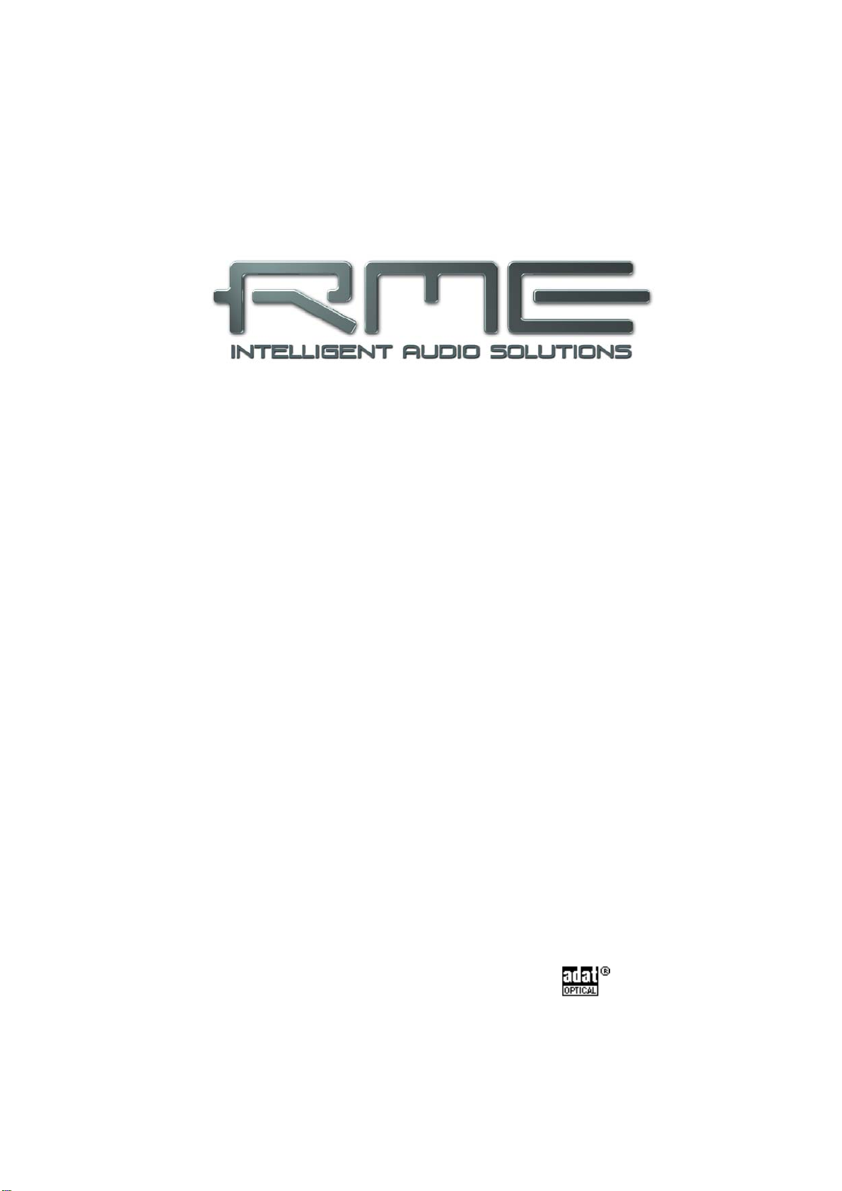
The front of the DMC-842 features eight LED level meter, eight
numerical LED displays, eight Select keys, a rotary encoder,
further keys for more specific configuration options, and 69
LEDs providing a detailed status display.
Each channel has a dedicated configuration area on the front
plate. The display GAIN shows the currently set amount of
amplification. The 13-segment LEVEL meter with switchable
Peak Hold function shows the incoming digital level.
The SELECT button is used for a per-channel activation / deac-
tivation of:
GAIN Amount of amplification
DPP Digital Phantom Power
STEREO Stereo mode
M/S Mid/Side encoding
SRC Sample Rate Converter
The LEDs MODE 2 and SYNC are skipped, as these are
status displays only. The also skipped LED PAR stands for the
Parameter settings mode (see below).
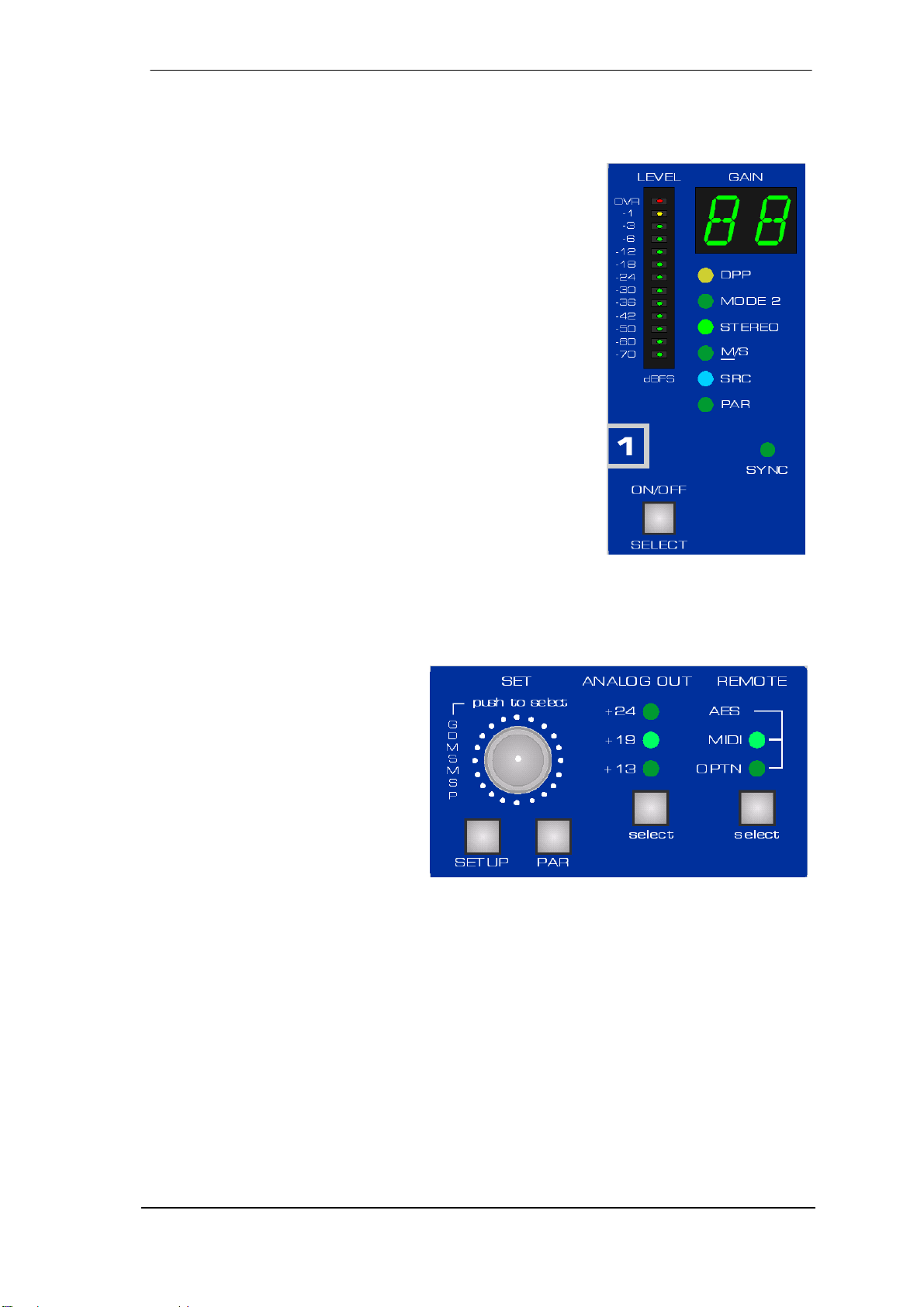
Pushing the knob SET several times lets you access all functions consecutively. The rotary
encoder is a highly intuitive multifunctional device. It is used to set the gain, to select the desired
function, to deactivate the function of one or all channels, to select various options in the Setup
menu and to perform the setting of the parameters.
The key ANALOG OUT defines the
analog reference level at the analog
outputs. This level is reached at full
scale of the DA-converters, thus
matching the front panel level meter's
level indication.
REMOTE defines the source for MIDI
remote control operation (Option Slot
/ MADI, D-sub AES1 or DIN jack).
After pressing the SETUP button the device enters the Setup menu, where many more options
can be configured. More information can be found in chapter 10.
After pressing the PAR button the device enters the Parameter menu. More information can be
found in chapter 11.
In the CLOCK SECTION the current clock reference and frequency multiplier is chosen.

8 User’s Guide DMC-842 © RME
The rear panel of the DMC-842 has eight AES42 inputs, eight analog outputs, mains power,
MIDI I/O, word clock I/O, the I64 Option Slot, and all digital inputs and outputs (AES/ADAT).
DIGITAL MICROPHONE – AES/EBU INPUTS (XLR): Eight balanced AES42 inputs with
switchable digital phantom power (DPP). These inputs are compatible to AES3 and AES/EBU.
ANALOG LINE BALANCED OUTPUTS (XLR): Eight balanced line outputs with up to +27 dBu
level.
AES I/O (25-pin D-sub): The D-sub connector provides four AES/EBU outputs and one
AES/EBU input (clock synchronization). The 25 pin D-sub connector is wired according to the
widely spread Tascam standard (pinout see chapter 18.9). The AES I/Os are transformer-
coupled.
ADAT OUT (TOSLINK): Optical ADAT outputs. These provide the same signals as the
AES/EBU outputs, but in ADAT format.
WORD IN (BNC): A push switch allows to activate internal termination (75 Ohms).
WORD OUT (BNC): Standard word clock output.
MIDI I/O (5-pin DIN): MIDI input and output via 5-pin DIN jacks. Used to remote control the
DMC-842, and – with installed MADI Card - to transmit MIDI data via MADI.
IEC receptacle for power connection. The specially developed, internal hi-performance switch
mode power supply lets the DMC-842 operate in the range of 100V to 240V AC. It is short-
circuit-proof, has an integrated line-filter, is fully regulated against voltage fluctuations, and sup-
presses mains interference.
With installed I64 MADI Card:
MADI I/O optical: Standard MADI ports.
MADI I/O koaxial (BNC): Standard MADI ports.

User’s Guide DMC-842 © RME 9
4.2 Quick Start
After connection of all cables and power-on of the device, the configuration of the DMC-842
begins in the CLOCK section. Choose a clock source and a sample rate. The next step is the
configuration of the input channels. When using digital microphones DPP (digital Phantom
power) must be activated. In Mode 1 the SRCs have to be activated as well as soon as more
than one microphone is connected.
The next step is the GAIN setting. This can be done in two ways:
•Individually: Hit the SELECT button of one or several channels. The corresponding GAIN
displays start flashing. Select the desired value with the rotary encoder. Or:
•Globally: Push the encoder knob once. All GAIN displays start flashing. Select the desired
value with the rotary encoder.
The flashing stops automatically after about six seconds. The LEVEL meter serves as comfort-
able tool to check whether gain is sufficient or already overloading the input.
To activate a function, press the SET knob repeatedly until the corresponding LEDs are flash-
ing. Pressing once all GAIN displays start flashing (gain setting), pressing twice selects all DPP,
then STEREO and so on. To activate or deactivate a specific function per channel, the corre-
sponding SELECT button is used. They are therefore also labeled ON/OFF.
The DMC-842 stores all settings before switching off, and sets them automatically when switch-
ing on the next time. The storing process is triggered about 4 seconds after the last change.
Using the included Windows software, the device’s complete state can be stored and archived.
5. Accessories
RME offers several optional components for the DMC-842:
Part Number Description
OK0050 Optical cable, Toslink, 0.5 m (1.7 ft)
OK0100 Optical cable, Toslink, 1 m (3.3 ft)
OK0200 Optical cable, Toslink, 2 m (6.6 ft)
OK0300 Optical cable, Toslink, 3 m (9.9 ft)
OK0500 Optical cable, Toslink, 5 m 16.4 ft)
OK1000 Optical cable, Toslink, 10 m (32.8 ft)
BO25MXLR4M4F1PRO Digital Breakout Cable Pro, AES/EBU
25-pin D-sub to 4 x XLR male + 4 x XLR female, 1m (3.3 ft)
BO25MXLR4M4F3PRO same, 3 m (9.9 ft)
BO25MXLR4M4F6PRO same, 6 m (19.8 ft)
BO25M25M1PRO Digital D-sub Cable Pro, AES/EBU
25-pin D-sub to 25-pin D-sub, 1m (3.3 ft)
BO25M25M3PRO same, 3m (9.9 ft)
BO25M25M6PRO same, 6m (19.8 ft)

10 User’s Guide DMC-842 © RME
I64 MADI Card MADI module featuring thru-input, Delay Compensation, Auto ID, MIDI
over MADI, remote via MADI
BOB32 BOB-32, Universal breakout box, 19" 1 Unit height. The professional
digital AES/EBU breakout solution
6. Warranty
Each individual DMC-842 undergoes comprehensive quality control and a complete test at IMM
before shipping. The usage of high grade components allow us to offer a full two year warranty.
We accept a copy of the sales receipt as valid warranty legitimation.
If you suspect that your product is faulty, please contact your local retailer. The warranty does
not cover damage caused by improper installation or maltreatment - replacement or repair in
such cases can only be carried out at the owner’s expense.
Audio AG does not accept claims for damages of any kind, especially consequential damage.
Liability is limited to the value of the DMC-842. The general terms of business drawn up by Au-
dio AG apply at all times.
7. Appendix
RME news and further information can be found on our website:
http://www.rme-audio.com
Distributor: Audio AG, Am Pfanderling 60, D-85778 Haimhausen, Tel.: (49) 08133 / 91810
Manufacturer:
IMM Elektronik GmbH, Leipziger Strasse 32, D-09648 Mittweida
Trademarks
All trademarks and registered trademarks belong to their respective owners. RME, SyncAlign,
Hammerfall, DIGICheck, SyncCheck and ZLM are registered trademarks of RME Intelligent
Audio Solutions. MultiMode, SteadyClock, DMC-842, I64 Option Slot, I64 MADI Card and Intel-
ligent Clock Control (ICC) are trademarks of RME Intelligent Audio Solutions. Alesis and ADAT
are registered trademarks of Alesis Corp. ADAT optical is a trademark of Alesis Corp. S/MUX is
copyright Sonorus.
Copyright ©Matthias Carstens, 10/2007. Version 1.0
All entries in this User's Guide have been thoroughly checked, however no guarantee for cor-
rectness can be given. RME cannot be held responsible for any misleading or incorrect informa-
tion provided throughout this manual. Lending or copying any part or the complete manual or its
contents as well as the software belonging to it is only possible with the written permission from
RME. RME reserves the right to change specifications at any time without notice.
User’s Guide DMC-842 © RME 11
CE / FCC Compliance
CE
This device has been tested and found to comply with the limits of the European Council Direc-
tive on the approximation of the laws of the member states relating to electromagnetic compati-
bility according to RL89/336/EWG and RL73/23/EWG.
FCC
This equipment has been tested and found to comply with the limits for a Class A digital device,
pursuant to Part 15 of the FCC Rules. These limits are designed to provide reasonable protec-
tion against harmful interference when the equipment is operated in a commercial environment.
This equipment generates, uses, and can radiate radio frequency energy and, if not installed
and used in accordance with the instruction manual, may cause harmful interference to radio
communications. Operation of this equipment in a residential area is likely to cause harmful
interference in which case the user will be required to correct the interference at his own ex-
pense.
RoHS
This product has been soldered lead-free and fullfills the requirements of the RoHS directive.
ISO 9001
This product has been manufactured under ISO 9001 quality management. The manufacturer,
IMM Elektronik GmbH, is also certified for ISO 14001 (Environment) and ISO 13485 (medical
devices).
Note on Disposal
According to the guide line RL2002/96/EG (WEEE – Directive on Waste
Electrical and Electronic Equipment), valid for all european countries, this
product has to be recycled at the end of its lifetime.
In case a disposal of electronic waste is not possible, the recycling can
also be done by IMM Elektronik GmbH, the manufacturer of the DMC-842.
For this the device has to be sent free to the door to:
IMM Elektronik GmbH
Leipziger Straße 32
D-09648 Mittweida
Germany
Shipments not prepaid will be rejected and returned on the original sender's costs.

12 User’s Guide DMC-842 © RME

User’s Guide DMC-842 © RME 13
User’s Guide
DMC-842
Usage and Operation

14 User’s Guide DMC-842 © RME
8. Front Panel Controls
8.1 Select Key and Rotary Encoder (SET)
The rotary encoder SET is a highly intuitive multifunctional device. It is used to set the gain, to
select the desired function, to deactivate the function of one or all channels, to select various
options in the Setup menu and to perform the setting of the parameters.
To activate a function, press the SET knob repeatedly until the corresponding LEDs are flash-
ing. Pressing once all GAIN displays start flashing (gain setting), pressing twice selects all DPP,
then STEREO and so on.
To activate or deactivate a specific function per channel, the corresponding SELECT button is
used. They are therefore also labeled ON/OFF.
Each channel offers the following functions:
GAIN Amount of amplification
DPP Digital Phantom Power
MODE 2 Status display, not selectable
STEREO Only odd chanels: Stereo mode
INACTIVE Only even channels: when Stereo mode had been activated
M/S Mid/Side encoding
SRC Sample Rate Converter
PAR Parameter configuration, not selectable
SYNC Sync state display, not selectable
The LEDs MODE 2 and SYNC are skipped, as these are status displays only. The also
skipped LED PAR stands for the Parameter settings mode (see chapter 11).
Setting the GAIN can be done in two ways:
•Individually: Hit the SELECT button of one or several channels. The corresponding GAIN
displays start flashing. Select the desired value with the rotary encoder. Or:
•Globally: Push the encoder knob once. All GAIN displays start flashing. Select the desired
value with the rotary encoder.
When adjusting several channels at the same time, the relation between individual channels will
be retained. So the gain of multiple channels can be increased or decreased without them loos-
ing their level relations. In case one of the linked channels reaches the highest or lowest gain
value (0 or +63 dB), the gain relationship gets lost.
Turning the encoder knob to the left initiates a global OFF command for all selected (flashing)
channels. For example, DPP can be switched off for all channels by pressing the encoder knob
twice and then turning it to the left by four ticks. The corresponding global ON command (a turn
to the right by at least four ticks) is also implemented.
For safety reasons, the DMC-842 will leave the selected function after 6 seconds. This may
seem cumbersome when changing the gain frequently, because the gain function will have to
be selected every time via the Select button or the encoder first. On the other hand, the DMC-
842 is absolutely safe from accidental changes.

User’s Guide DMC-842 © RME 15
8.2 Clock Section
The source and frequency of the unit's clock is configured in the CLOCK SECTION. The button
CLOCK lets you step through the options external clock (Word, AES, Option = MADI) and inter-
nal clock. The button SAMPLE RATE sets the sample rate for both external and internal clock.
WCK, AES, OPTN (Slave Mode)
Defines the corresponding input as clock reference. A missing or invalid clock source signal is
indicated by flashing of the corresponding LED.
INT (Master Mode)
Activates the internal clock.
With a setting of INT (internal clock) it is mandatory that the clock rate of the sources is
synchronous to the DMC-842. Therefore the external device has to be synchronized to the
DMC-842's word clock output or AES/ADAT/MADI output.
The DMC-842 thus has to be master, all devices connected to it must be slave. In order to avoid
clicks and drop outs due to faulty or missing synchronicity, a special process called SyncCheck
compares the incoming data and the DMC-842's internal clock. The SYNC state is indicated by
a flashing (error) or turned off (OK) LED.
44.1, 48
Activates the internal clock at 44.1 kHz or 48 kHz.
DS, QS
With the DS LED additionally lit, the sample rate will be 88.2 or 96 kHz, with QS lit it will be
176.4 or 192 kHz.
A selection of DS and QS is also possible when using external clock (Slave). If the DMC-842
should operate at 192 kHz, but receives a synchronous word clock of 48 kHz, the button
SAMPLE RATE allows to activate DS or QS mode. This way, AD-conversion and digital outputs
are configured to operate in the frequency ranges Single Speed, Double Speed or Quad Speed.
Single Speed
All outputs carry a signal in the range of 32 kHz up to 48 kHz.
DS (Double Speed)
The AES outputs 1-8 carry a signal in the range of 64 kHz up to 96 kHz. ADAT and MADI stay
at no higher than 48 kHz, with the data transmitted in the S/MUX format.
QS (Quad Speed)
The AES outputs 1-8 carry a signal in the range of 176.4 kHz up to 192 kHz. ADAT and MADI
stay at no higher than 48 kHz, with the data transmitted in the S/MUX4 format. Therefore ADAT
is limited to 4 channels (2 per optical output) in this mode.
8.3 Analog Out
The button ANALOG OUT is used to set the analog reference level at the analog outputs. This
level is reached at full scale of the DA-converters, thus matching the front panel level meters
level indication.
Reference 0 dBFS @ Analog Headroom
+24 +24 dBu 3 dB
+19 +19 dBu 8 dB
+13 +13 dBu 14 dB

16 User’s Guide DMC-842 © RME
8.4 Remote
REMOTE defines the source of MIDI remote control commands. Choices are the MIDI DIN jack,
the D-sub AES1 and the MADI input of the I64 MADI Card (Option Slot).
Note: Via MIDI remote control, all front panel controls can be locked (Lock Keys). An exception
is the REMOTE key. In Off-state Lock Keys is deactivated. Therefore a locking of all the
controls can be revoked directly at the unit at any time.
9. The Input Channel in Detail
9.1 General
Each channel has a dedicated configuration area on the front plate. The display GAIN shows
the currently set amount of amplification. The 13-segment LEVEL meter with switchable Peak
Hold function shows the digital signal level after Gain control, but before SRC, stereo and M/S
processing, as shown in the block diagram (chapter 20). The SELECT button is used to select a
channel, but also to activate/deactivate the different functions (DPP, STEREO etc).
9.2 Gain
The DMC-842's GAIN can be set individually per channel over a range of 0 db up to +63 dB, in
steps of 1 dB. The device has its own gain control, operational even in the asynchronous Mode
1, and – as shown in the block diagram – is placed in front of the SRCs. When the microphone
signals support for gain control, the DMC-842’s gain stage is deactivated automatically by set-
ting it to 0 dB internally.
The gain can not be set directly for inactive channels. Therefore in Stereo mode the gain dis-
play of the right channel is turned off.
9.3 Digital Phantom Power
The LED DPP indicates activated digital phantom power for the XLR input. Phantom power
should only be activated when using digital microphones.
Connecting and disconnecting microphones while phantom power is active causes a volt-
age surge, which can destroy components. Switch phantom power off before connect-
ing/disconnecting any external device.
As called for in the AES42 standard, the DMC-842 provides a common mode voltage of 10
Volts on both input pins. When connecting fully balanced AES/EBU outputs, this voltage theo-
retically stays without effect. Nevertheless we strongly recommend to switch off DPP in such
cases. When connecting unbalanced outputs (AES-ID or SPDIF) a current is expected to flow
through the output stage of the feeding device!

User’s Guide DMC-842 © RME 17
9.4 Mode 2
In Mode 1 the digital microphone is clock master, operating from the internal and fixed fre-
quency. When connecting more than one microphone, the usage of sample rate converters for
clock-decoupling is unavoidable.
In the newer Mode 2 the digital microphone is clock slave. The DMC-842 determines the fre-
quency and generates a digital control signal for each microphone. A sample rate conversion is
not required in this case.
The microphone signals the supported mode, the DMC-842 switches its input accordingly. The
LED MODE 2 therefore is a state display only.
Note: Not every digital microphone supports Mode 2. With regard to the outstanding SRC built
into the DMC-842 Mode 1 can be seen as equally good alternative. However the SRCs delay
the audio signals by about 141 samples. At 44.1 kHz, this equals about 3 ms.
9.5 Stereo / Inactive
The DMC-842 has 8 single AES/EBU compatible inputs, being a 2-channel (stereo) input each.
At the time of printing this manual, digital stereo microphones not yet exist. A digital microphone
therefore provides only the information of one channel per input. For maximum flexibility the
operation mode can be switched between 2-channel and 1-channel. The labeling of the input
XLR connectors has been done to signal this flexibility. The odd ones are labeled Stereo (1/2),
the even ones Mono (2).
When an odd channel is switched into STEREO mode, the according even channel’s INACTIVE
LED lights up automatically. The gain can not be set directly for inactive channels. Therefore in
Stereo mode the gain display of the right channel is turned off.
9.6 M/S Processing
The DMC-842 includes a digital M/S processor. The channels have a fixed assignment: all odd
ones are M, all even ones are S. The front panel shows an according labeling:
Channel 1 M/S (D)
Channel 2 M/S (D)
The mid/side principle is a special positioning technique for microphones, which results in a mid
signal on one channel and a side signal on the other channel. The DMC-842’s M/S processor
transforms these information back into a standard stereo signal. The process sends the monau-
ral mid channel to left and right, the side channel too, but phase inverted (180°) to the right
channel. For a better understanding: the mid channel represents the function L+R, while the
side channel represents L-R.
The M/S-Processing automatically operates as M/S encoder or decoder, depending on the
source signal format. When processing a usual stereo signal, all monaural information will be
shifted into the left channel, all stereo information into the right channel. Thus the stereo signal
is M/S encoded. This yields some interesting insights into the mono/stereo contents of modern
music productions. Additionally some very interesting methods of manipulating the stereo base
and generating stereo effects come up, as it is then very easy to process the side channel with
Low Cut, Expander, Compressor or Delay. The most basic application is to change the level of
the side channel: this allows to manipulate the stereo width from mono to stereo up to extended
in a stepless way.

18 User’s Guide DMC-842 © RME
9.7 SRC
The DMC-842 includes eight individually switchable sample rate converters (SRC). The techni-
cal specifications indicate an exceptional conversion quality, formerly known only from synchro-
nous SRC devices. The conversion in full 24 bit resolution operates practically without loss of
signal quality, so no audible artifacts or noise are added.
The SRC of the DMC-842 offers a maximum conversion rate of 1:7 or 7:1, respectively. Thus,
192 kHz can be converted to any sample rate down to 32 kHz, and 32 kHz can be converted to
any frequency up to 192 kHz.
When using the internal clock, every SRC also works as a jitter killer. However, the DMC-842 is
equipped with SteadyClock, thus operating as perfect jitter killer with any clock source.
An SRC not only converts sample rates, it also serves as a clock decoupler. With SRC active,
even non-synchronizable devices (CD-players, DAT machines, etc.) can be used in a setup of
digital devices, just as if they were externally synchronized. The SRC decouples input and out-
put clock, sets the output clock to the common reference, thus allowing the combination of dif-
ferent clock-sources without any clicks or dropouts. This is exactly what happens when using
digital microphones in Mode 1.
9.8 PAR
After pressing the PAR button below the rotary encoder the DMC-842 enters the Parameter
menu. Turning the encoder knob scrolls through all the available options. More information can
be found in chapter 11.
9.9 Sync
The DMC-842 has 8 independent digital inputs. In order to avoid clicks and drop outs due to
faulty or missing synchronicity, a special process called SyncCheck analyzes the incoming
data.
Each input has its own SYNC LED. If a valid input signal is applied, SyncCheck is active auto-
matically. SyncCheck takes the chosen clock (internal, external, etc.) as reference and com-
pares it with the input clocks. Inputs which are not synchronous will be signalled by flashing of
the corresponding SYNC LED.

User’s Guide DMC-842 © RME 19
10. The Setup Menu
10.1 General
Some options and settings are accessed and changed very seldomly. These have been col-
lected in the Setup menu. The Setup menu is entered by pushing SETUP, situated below the
encoder. SEt is displayed on the left part of the Gain displays. Turning the encoder scrolls
through all the options, displayed as abbreviation in the right part of the Gain displays.
The Select key 8 allows to toggle the current setting, for example changing between On and
Off. Otherwise the Select keys 7 and 8 can be used to increase/decrease the current value, for
example the ID (1 to 8).
All changes are stored automatically. With a second push on the SETUP key the Setup menu is
exit.
10.2 ID (Id)
Default: 01
Available settings: 01, 02, 03, 04, 05, 06, 07, 08
To remote control more than one DMC-842 each device can have its own ID, providing a sepa-
rated remote control of multiple devices via a single MIDI channel.
I64 MADI Card: The ID also defines the 8-channel group within the MADI signal that is used to
insert the device's audio data:
ID 01: channels 1-8 ID 02: channels 9-16 ID 03: channels 17-24
ID 04: channels 25-32 ID 05: channels 33-40 ID 06: channels 41-48
ID 07: channels 49-56 ID 08: channels 57-64
When several DMC-842, Micstasy, ADI8-QS or ADI-642 units are connected via MADI, Auto ID
normally takes care of the channel assignment (see chapter 10.4, Auto ID). In special cases, it
may be desirable to set the ID manually, e.g. if the first device in a MADI chain does not support
the Auto ID mode, or if a group of eight channels needs to be routed or processed in a particu-
lar way.
With activated mode Digital Out the ID also defines which MADI input channels are sent to the
ADAT/AES outputs, see chapter 10.9. With activated mode Analog Out the ID also defines
which MADI input channels are sent to the analog outputs, see chapter 10.10.
Note: When the device is Auto ID Slave, the displayed ID can not be changed manually.
10.3 Bank (bA)
Default: 01
Available settings: 01, 02, 03, 04, 05, 06, 07, 08
To remote control more than one DMC-842 each device can have its own ID (chapter 10.2),
providing a separated remote control of multiple devices via a single MIDI channel. Additionally,
not only 8 IDs but 8 banks of 8 IDs each are available.
20 User’s Guide DMC-842 © RME
10.4 Auto ID (Au)
Default: Off
Available settings: On, Off
This option relates to the use of the I64 MADI Card. Multiple DMC-842 (and ADI-
642/Micstasy/ADI-8 QS, see chapter 14.3/14.4) connected serially can assign consecutive IDs
to themselves. For this to happen, Auto ID is set to On at the first device of the chain. All other
devices automatically turn into slaves. An Auto ID slave has the middle dot lit in the GAIN dis-
play of channel 8.
10.5 Delay Compensation (dC)
Default: 0ff
Available settings: On, Off
This option relates to the use of the I64 MADI Card. When multiple devices are connected seri-
ally, the MADI I/O of each DMC-842 causes a delay of 3 samples. Therefore at the MADI output
of the last device, the data of all upstreamed devices are delayed. At Double Speed the delay
rises to 6 samples per unit, at Quad Speed to 12 samples.
The problem of this offset is solved by the function Delay Compensation. It delays the signals in
a way that they are sample-synchronous in multi-device operation.
Delay Compensation has to be manually activated in each unit!
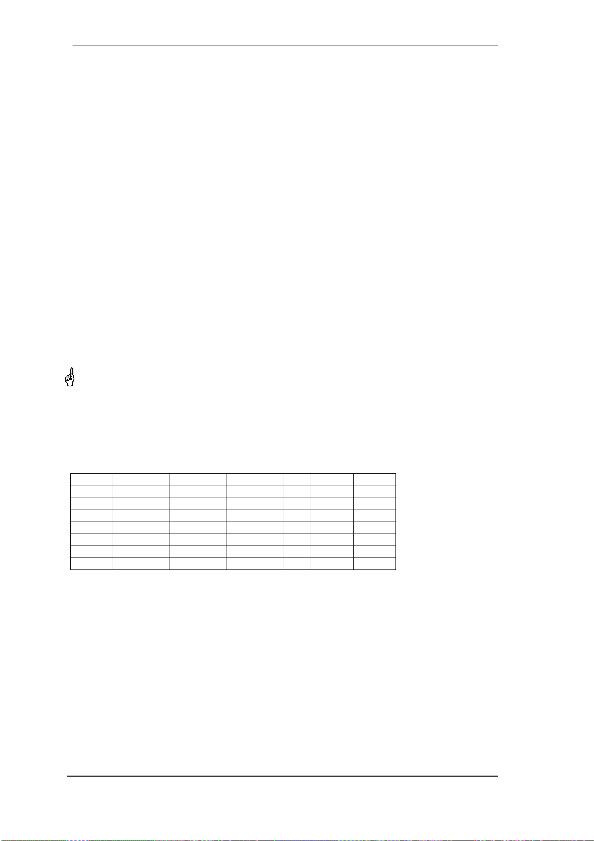
The following table lists the delay in samples from two up to eight units connected serially.
When using four units, the data of the first unit are delayed by 9 samples to the last unit, the
units 2 and 3 are delayed by 6 and 3 samples respectively. At Double Speed and Quad Speed
the values rise. Please note that in Double Speed no more than four, in Quad Speed no more
than two DMC-842 can be used serially with MADI.
Units Delay Delay DS Delay QS DC DC DS DC QS
2 3 6 12 21 18 12
3 6 12 - 21 18 -
4 9 18 - 21 18 -
5 12 - - 21 - -
6 15 - - 21 - -
7 18 - - 21 - -
8 21 - - 21 - -
As shown in the table, activating DC causes a constant delay of 21 samples in Single Speed,
no matter how many devices are connected serially. In Double Speed the delay is 18, in Quad
Speed 12 samples. The in most cases slightly increased delay is outweighed by the big advan-
tage of sample-aligned I/Os when using multiple units.
Delay Compensation always uses the worst case, the operation of 8 units, but delays the sig-
nals individually. The amount of the respective delay is solely derived from the current ID, no
matter if it has been assigned manually or by Auto ID.
21 samples @ 48 kHz
equal 437 µs.
18 samples @ 96 kHz
equal 187 µs.
12 samples @ 192
kHz equal 62.5 µs.
This manual suits for next models
1
Table of contents
Other RME Audio Amplifier manuals


