8
Setting the temperature
Temperature adjustments are done by holding the button and pressing either or
Confirmthe settings byletting go of thebuttons.
Lighting inside the cabinet
-Only applicableto cabinets with glass doors -
The settings for the lighting inside the cabinet can be turned oby pressing and holding
for 3seconds.
There are two settings:
1) Light turns on when the door is open(owhen closed)
2) Light is always on
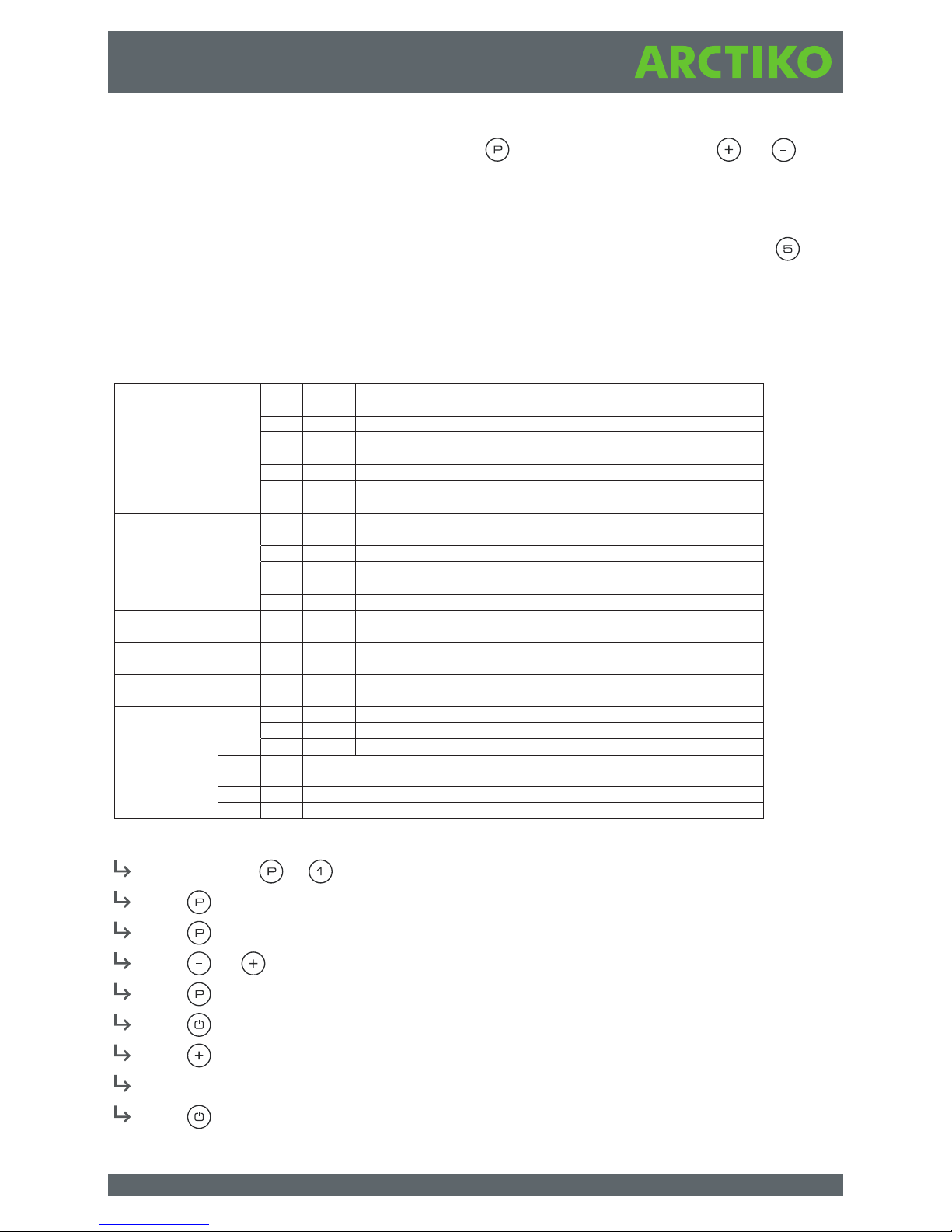
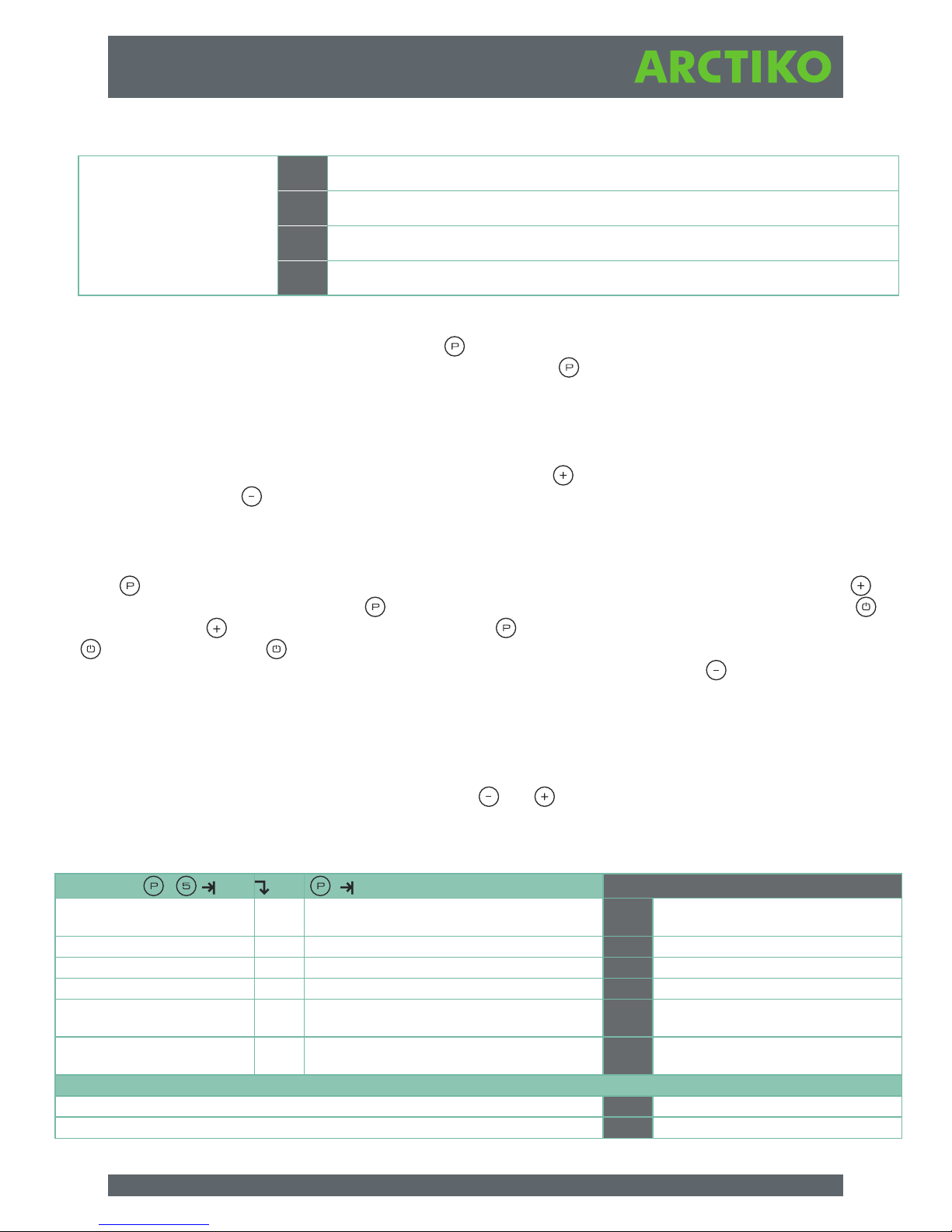
User menu and alarm settings
Example: Setting the upper limits for the alarms; LHL
Press and hold + until the display shows LAL
Press to select LAL,LHL is now shown in thedisplay
Press to select LHL, 25 is shown in the display
Press or to set thedesired value for theupper temperature limit
Press to conrm the set value
Press to return to LAL
Press to reach the next level, LLL
LHd,LLd, dA,dAd and bU are located on thesame level
Press three times to leave the user menu
Local alarm LAL LhL (°C) Upper temperature limit. Code for activated alarm: (A2)
LLL (°C) Lower temperature limit. Code for activated alarm: (A3)
Lhd (min.) Delay of uppe timil e r u ta repmet r
timil eru tar epmet rewo l f o yaleD ).n im( dLL
dA On/off Door alarm. Code for activated alarm: (A1). (1=on / 0=off)
mr a l a r ood f o ya l eD ) . n im( dAd
BU On/off Acoustic signal at alarms: Codes (A1), (A2), (A3). (1=on / 0=off)
External alarm EAL EhL (°C) Upper temperature limit Code for activated alarm: (A4)
ELL (°C) Lower temperature limit Code for activated alarm: (A5)
Ehd (min.) Delay of uppe timil eru tar epmet r
timil eru tar epmet rewo l f o yaleD ).n im( dLE
dA On/off Door alarm. Code for activated alarm: (A1). (1=on / 0=off)
mr a l a r ood f o ya l eD ) . n im( dAd
BU On/off Acoustic signal at alarms: Codes (A1), (A4), (A5). (1=on / 0=off)
Calibration of
sensors
cAL cA (°K) Offset settings of A-sensor. Reference sensor for the refrig. system
cE (°K) Offset settings of E-sensor. Reference sensor for display and alarms
cF (°K) Offset settings of F-sensor. Reference sensor for low temp. protection
Low-temp.
protection
ffo/no noitcetorp erutare pmet woL ffo/nO tcA PF
tES On Function test of the low temp. protection. Cut out of compressor =C4
erutarepmet tuo tuc eht fo gni t teS )C°( teS
ro sn es- F e ht no erutarepmet emit la er fo tuo d a eR )…( E r P
ALL Activation of escorted alarm limits. (FAS)=locked limits / (ESC)=follows set
points
sruoh 4 2 rep stsorfed fo rebmuN FEd
.)F ro E,A( ya l psi d eh t rof rosnes ecne re feR SPd