Arctiko BBR100 User manual

OPERATING INSTRUCTIONS
BLOOD BANK REFRIGERATOR
100/300/500/700/1400

INDEX......................................................PAGE
SafetyPrecautions..............................................................3
Installingtheappliance...........................................................7
ElectricalConnection............................................................7
Information ...................................................................7
Descriptions of Refrigerator Parts and Their Functions . . . . . . . . . . . . . . . . . . . . . . . . . . . . . . . . . . . 8
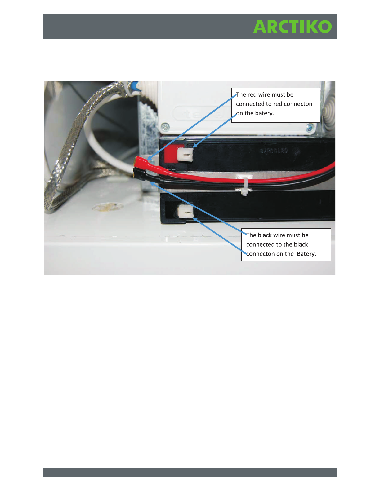
Before you start up the Refrigerator, you have to connect the Battery Backup . . . . . . . . . . . . . . . . . 10
HowtomounttheDoorHandle....................................................11
How to mount the Adjustable Devices in the Blood Storage Drawer . . . . . . . . . . . . . . . . . . . . . . . . . 12
LocationofRefrigerator .........................................................13
Installation...................................................................14
ControlPanel.................................................................15
DescriptionControlPanelforuser..................................................15
DescriptionControlPanelforengineer ..............................................16
Defaultsettings ...............................................................17
Operation....................................................................18
ChartRecorder................................................................19
ProperusageoftheRefrigerator...................................................23
Maintenance .................................................................24
CleaningtheRefrigerator ........................................................24
HowtochangetheFlourescentLightTube ...........................................25
Specifications.................................................................26
TheRatingPlate...............................................................28
After-Salesupport .............................................................29
DearCustomer................................................................29
SpareParts ..................................................................29
Guarantee ...................................................................29
BlockDiagramofMainPCBboard .................................................30
WiringdiagramforBBR500/700..................................................31
WiringdiagramforBBR1400.....................................................32

Safety Precautions
Environmental Conditions
This unit is designed for applications in the following environmental conditions. It is safe to operate the
unit at these or more favorable conditions:
. 1. Indoor usage.
2. Elevation of less than 2.000 meters.
3. Ambient temperature between 5° C to 32° C.
4. Voltage variation within ± 10 percent of nominal voltage supply.
5. Factory-approved abnormal voltage range.
6. Instantaneous over-voltage complies with second grade for installation of equipment. For the
main voltage supply, the minimum and normal supply is second level.
7. Environment complying with IEC664 standard, Grade 2 Contamination.
The Blood Bank unit is designed for
storage of whole blood and related
products at constant temperature in
clinical, pharmaceutical, research, and
other laboratory applications. Please
carefully read this manual, and follow the
instructions to properly operate the unit.
This manual covers all aspects of installing
and operating the unit. It also provides
information that can prevent a user from
being injured. «Caution» and «Warning»
suggest two levels of safety implications.
Please follow them carefully.
This action may cause fatal injury
or servere damage.
This action may cause fatal injury
or servere damage.
CAUTION
WARNING
Example of labels:
This symbol suggests precaution be followed
This symbol means that an action is strictly prohibited.
This symbol designates procedures to be followed.
Please keep this manual for convenient reference.
3

SAFETY PRECAUTIONS
Do not use the unit outdoors. Current leakage or electric shock may result if the unit is exposed
to rain water.
Only qualified engineers or service personnel should install the unit. The installation by
unqualified personnel may cause electric shock or fire.
Install the unit on a sturdy floor and take an adequate precaution to prevent the unit from
turning over. If the floor is not strong enough or the installation site is not adequate, this may
result in injury from the unit falling or tipping over.
Never install the unit in a humid place or a place where it is likely to be splashed by water.
Deterioration of the insulation may result which could cause current leakage or electric shock.
Never install the unit in a flammable or volatile location. This may cause explosion or fire.
Never install the unit where acid or corrosive gases are present as current leakage or electric
shock may result due to corrosion.
Always ground (earth) the unit to prevent electric shock. If the power supply outlet is not
grounded, it will be necessary to install a ground by qualified engineers.
Never ground the unit through a gas pipe, water main, telephone line or lightning rod. Such
grounding may cause electric shock in the case of an incomplete circuit.
Connect the unit to a power source as indicated on the rating label attached to the unit. Use
of any other voltage or frequency other than that on the rating label may cause fire or electric
shock.
Never store volatile or flammable substances in this unit if the container cannot be
sealed.These may cause explosion or fire.
Do not insert metal objects such as a pin or a wire into any vent, gap or any outlet on the
unit. This may cause electric shock or injury by accidental contact with moving parts.
WARNING
4

SAFETY PRECAUTIONS
Use this unit in safe area when treating the poison, harmful or radiate articles. Improper use
may cause bad effect on your health or environment.
Turn off the power switch (if provided) and disconnect the power supply to the unit prior to
any repair or maintenance of the unit in order to prevent electric shock or injury.
Do not touch any electrical parts (such as power supply plug) or operate switches with a wet
hand. This may cause electric shock
.Ensure you do not inhale or consume medication or aerosols from around the unit at the time
of maintenance. These may be harmful to your health.
Never splash water directly onto the unit as this may cause electric shock or short circuit.
Never put containers with liquid on the unit as this may cause electric shock or short circuit
when the liquid is spilled.
Never bind, process, or step on the power supply cord, or never damage or break the power
supply plug. A broken supply cord or plug may cause fire or electric shock.
Do not use the supply cord if its plug is loose. Such supply cord may cause fire or electric
shock.
Never disassemble, repair, or modify the unit yourself. Any such work carried out by an
unauthorized person may result in fire, or electric shock or injury due to a malfunction.
Disconnect the power supply plug if there is something wrong with the unit. Continued
abnormal operation may cause electric shock or fire.
When removing the plug from the power supply outlet, grip the power supply plug, not the
cord.Pulling the cord may result in electric shock or fire by short circuit.
Disconnect the power supply plug before moving the unit. Take care not to damage the power
cord. A damaged cord may cause electric shock or fire.
Disconnect the power plug when the unit is not used for long periods. Keeping the connection
may cause electric shock, current leakage, or fire due to the deterioration of insulation.
WARNING
5

SAFETY PRECAUTIONS
Use a dedicated power source (a dedicated circuit with a breaker) as indicated on the rating
label attached to the unit. A branched circuit may cause fire resulting from abnormal heating.
Connect the power supply plug to the power source firmly after removing the dust on the
plug. A dusty plug or improper insertion may cause a heat or ignition.
Never store corrosive substances such as acid or alkali in this unit if the container cannot be
sealed. These may cause corrosion of inner components or electric parts.
Check the setting when starting up of operation after power failure or turning off of power
switch. The stored items may be damaged due to the change of setting.
Be careful not to tip over the unit during movement to prevent damage or injury.
Prepare a safety check sheet when you request any repair or maintenance for the safety of
service personnel.
Always keep the keys in separate place and out of reach of children.
Before servicing or cleaning the appliance, unplug it from the mains or disconnect the
electrical power supply.
The power supply cable may only be replaced by an authorised person.
The packing material is entirely recyclable, please follow the local regulation for scrapping.
If the unit is to be stored unused in an unsupervised area for an extended period, ensure that
children do not have access and that doors cannot be closed completely.
The disposal of the unit should be accomplished by appropriate personnel. Remove doors to
prevent accidents such as suffocation.
Do not put the packing plastic bag within reach of children as suffocation may result.
CAUTION
6

Installing the appliance
Electrical Connection
1. Always allow an authorised electrician to install the appliance.
2. The appliance should be located in a cool, dry place out of direct sunlight. The appliance gives
off a great deal of heat when in operation. If the ambient temperature is too high there is a risk
that the appliance will not operate correctly. It is recommended that the room be ventilated so
that the room temperature does not exceed ambient temperature.
3. Place the appliance on a solid and flat substrate. This will eliminate any vibration an irritating
noise. The appliance should be placed with at least 10cm free to the sides, at least 16cm free at
the back.
The appliance meets current EU directives. Low voltage 2006/95/EEC.
Electromagnetic compatibility 2004/108/EEC.
Only use the appliance for its specific purpose
The appliance should be given extra protection in accordance with Electricity Supply Regulations in
order to protect the user against dangerous electric shocks in the event of faults.
If the switch is for three-pin plug, a three-pin plug should be used and the conductor with yellow/green
insulation connected to the Earth terminal.
Data regarding voltage and absorbed power/current is given on the rating plate. (see page 27)
Electrical connection must be made in accordance with the local regulations.
Information
This appliance contains a mixture of various refrigerants. For more information please se the plate
affixed to the refrigerator. (see page 27)
7

Descriptions of Refrigerator Parts and their Functions
1. Control panel
2. Light Power Switch
3. Battery Back-up
4. Door lock with key
5. Door Handle
6. Castors
7. Chart Recorder
8. Blood Storage Drawers
9. Interior Light
8. Adjustable Devices
11. Rating plate
8

Descriptions of Refrigerator Parts and their Functions
1. Control Panel (0 Clle)
The control panel on the blood bank shows the actual storage temperature inside the refrigerator. You
can use the push buttons on the panel to adjust the temperature set point and test the alarm functions.
2. Light Power Switch
You can use the switch to turn on and off the interior lights of the refrigerator.
3. Battery Back-up
Before you start up the refrigerator, you have to connect the Battery Back-up (see page 10)
4. Door Lock with key
You can use this feature to lock the refrigerator.
5. Door Handle (How to mount the Door Handle, see page 11)
For easy of opening and closing door.
6. Castors
The 4 castors underneath the unit provide the convenience of moving the unit around.
7. Automatic Temperature Recorder
The refrigerator is equipped with an automatic temperature recorder. Its paper chart runs for a full turn
in 7 days, o the storage temperature can be permanently recorded. The chart paper must be changed
once every 7 days.
8. Blood Storage Drawers with adjustable Devices
(How to mount the Devices, see page 12)
The drawers are designed to conveniently store and unload the blood samples.
9. Interior Light (How to change the Flourescent Light Tube, see page 24)
The light bulb is 15 Watts.
10. Door Alarm
When the door is open for 15 minutes, the door alarm will sound. You should reduce the open door
time to stabilize the refrigerator temperature.
11. Rating plate (See page 27)
9

Before you start the refrigirator and freezer, you have to connect the battery backup
10

How to mount the Door Handle
5. Mount a screw inside the Handle
both in top and bottom.
1. Door Handle with Fittings and Cover 2. Place the Fittings on the Door Handle.
3. Mount the Handle on the door with screws.
4. Push the cover for the Door Handle on its place.
11

How to mount the Adjustable Devices in the Blood Storage Drawer
Place the device in both split in the Drawer.
Push the device in its place.
12

1. Firm, level floor surface
Installing the unit on a firm and flat floor surface
reduces the chance of excessive noise and
vibration.
2. A place that is far away from any heat source.
Avoid placing the unit near any heat dissipating
devices such as a gas stove, radiator, oven
and other source of heat. The refrigerator would
lose its efficiency once the insulation is exposed
to heat.
3. Do not install a refrigerator in direct sunlight.
If a unit is in direct sunlight, it may not function
properly and its life expectancy can be
shortened.
4. Dry area
Avoid placing the unit near damp areas such as
a water faucet and sink.
5. Clean area
Avoid installing a unit in or near chemical
materials and materials that might have out-
gassing property. Also avoid dusty locations.
6. Good ventilation
There must be sufficient space around the unit
for air ventilation. Lack of such space will reduce the unit’s cooling capability.
7. Ground protection
Grounding the refrigerator will prevent electrical shock to operators if its electrical insulation
become weak.
8. Do not place any objects on top of the
refrigerator.
Location of Refrigerator
Your refrigerator should be placed on a location that satisfies the following conditions. By doing so, the
optimum operating results can be achieved.
An electrical power plug with
a ground prong must be used
to power the unit. This is to
prevent electrical shock.
Do not use water lines to
replace a properly installed
ground wire for ground
protection. This is because
many water lines are actually
built with non-conductors
such as plastic.
Never use gas lines as the
ground protection for the
refrigerator. This action can be
very dangerous.
Never use a telephone line or
lightning rod as a grounding
protection for the refrigerator.
This is because during
lightening, there is a strong
current present which is
extremely dangerous
WARNING
CAUTION
Do not place the unit in an area
where objects can fall directly onto
it. This is to avoid damaging the
refrigerator.
13

Installation
1. Remove packaging materials, packaging bags and straps.
Open the refrigerator door to let it air out. If there are dirt marks on the outside of the unit, use a
soft sponge with a light detergent solution to wipe the unit clean. Then, rinse the unit with a clean,
slightly damp towel.
2. Adjust the height of the unit.
Turn the leveling leg screw counterclockwise to level the front end of the unit. The front casters
should be off the ground.
3. Preparation of sensor bottle.
Before using the refrigerator, inspect the sensor bottle located at the back of the drawers and
shelves to see if the liquid level is up to the 200 mark inside the bottle. If the bottle has no fluid or
the fluid level is lower than the 200 mark, use the following steps to fill the bottles at the upper
corner and the lower corner with solution of 10% glycerin concentration (or other equivalent liquid
such as glycerin solution).
(1) Remove the top drawer, bottom drawer, shelves and baskets.
(2) Unscrew the fastener that positions the bottle, remove the bottle.
(3) Unscrew the bottle’s cap that is used for the sensor mounting.
(4) Pour a solution of 10% glycerin concentration into the bottle(s) to the 200 mark line.
(5) Mount the bottle back to the refrigerator liner wall.
(6) Install the bottle back to its original position. Place the temperature sensor back inside the
temperature bottle.
14

Cl el (Dixell XR30CX)
Description control panel for user
Description of marked points from control panel overview
1 Accept current alarm
Current alarms will be shown on the screen
2 Accept non current alarm(s) not accept
Non current alarms will be shown on the screen
3 Temp. Last 24 H max/min
The highest and lowest temperature of the unit, the last 24 hours will be shown on the screen.
4 Setpoints
The wanted temperature of the unit.
5 Power failure
If the main power to the unit disappear, an alarm will occur. The data logger will still log the data.
To keep current on the battery as long as possible, the light in the display will disappear.
6 High temp alarm
Temperature too high for longer time than alarm delay
7 Low temp alarm
Temperature too low for longer time than alarm delay
8 Door op alarm
If the door is left open, the door alarm will be activated.
9 Probe/eprom failure
If there is a failure on the probe or on the eprom the alarm will be activated
10 Alarm delay
Delay before Alarm Hi/Lo temp alarm is activated.
11 Alarm log
Log all current and not current alarms.
Up, down, left, right button
to scrolls through the menu
Mute alarm
On/off or exit menu
Alarm (red light)
Enter (accesses the menu, accept)
Screen
At alarm
Main menu
Temp. Last 24 H max/min 3)
Settings level l password l Settings level ll password ll
Setpoints 4)
Alarm settings
Power failure 5)
High temp alarm 6)
Low temp alarm 7)
Door op alarm 8)
Probe/eprom failure 9)
Alarm delay 10)
Alarm log 11)
Current alarm
Non current alarm(s)
not accept
Accept 1)
Accept 2)
15

Screen
Main menu
At alarm
Temp. Last 24H max/min
Settings level l password Settings level ll password ll
Hysteresis 13)
Range
On/off
Calibration 17)
Automatic defrost 18)
Change passwords
Service menu
Reset all settings to fabric default 23)
Max temp limit 14)
Min temp limit 15)
Password protected yes/no 16)
Yes. Password
No
Yes
No
Defrost cyclus
Start manual defrost
Change password l 19)
Change password ll 20)
Compressor hours 21)
Fan hours 22)
Description control panel for engineer
13 Hysteresis
The difference between the set point and the temperature that
causes the fan and the compressor to restart.
14 Max temp limit
Max. set point allowed to be set on level I
15 Min temp limit
Min. set point allowed to be set on level II
16 Password protected Yes/no.
Password for start/stop the freeer Yes or No?
17 Calibration
The temperature sensor of the unit can be calibrated.
This value represents the offset +/- from the value in the display.
18 Automatic defrost
Yes: Defrost cyclus
Adjust how many times the unit must automatic defrost.
No: manual defrost
The unit will only defrost when manual defrost is being
activated.
19 Change password l
Changes the password to level 1
20 Change password ll
Changes the password to level 2
21 Compressor hours
Compressor running time?
22 Fan hours
Fan running time
23 Reset all settings to fabric default
All settings will be deleted and turn back to factory settings.
16

Default
settings:
Description Arctiko defau lt
settings
Customer
setting.
LEVEL I
Password 0000
Set point
Refrigerator +4
Power failure
Refrigerator 01 (on)
High temp alarm
Refrigerator +6
Low temp alarm
Refrigerator +2
Door open alarm
Refrigerator 01
Probe/eprom failure
Refrigerator 01
Alarm Delay
Refrigerator 01
Alarm log
Refrigerator 01
Description Arctiko default
settings
Customer
setting.
LEVEL II
Password 0000
Hy st er es is
Refrigerator 2
Max temp limit
Refrigerator +8
Min te mp limit
Refrigerator +0
Password protected on/off
Refrigerator Off
Calibration
Refrigerator 00
Automatic defrost
Refrigerator 06
17

Unit’s refrigeration is not effective.
Temperature tends to operate out of range.
The unit is too noisy.
Alarm light flashes, alarm buzzer sounds.
1. Inspect to see if the unit is overloaded or
products with warm temperature have been
loaded into the unit.
2. Make sure there is an air gap between
products.
3. Check to make sure the unit is not in direct
sunlight or subject to any heat radiation.
4. Investigate to see if there have been
frequent door openings.
5. Investigate to see if the environment
temperature is too high.
6. Inspect air channels to see if they are
blocked.
7. Check the condenser air filter to see if it is
clogged with dirt.
1. Make sure the unit is placed on a level floor.
2. Make sure any part of the unit does not
touch a wall or any object.
1. If warm blood products are just loaded to
the unit, allow ample time for the
temperature to recover. The alarm signal
cancels when the temperature recovers to
normal level.
2. Inspect the door to make sure it is shut
properly. Door ajar alarm can sound if the
door is slightly opened.
3. There might be insufficient power supply.
Let it run for some time to recover.
4. Check the temperature of the unit to see if it
is in over-temperature condition.
Operation
18

Chart Recorder
The Chart Recorder is device intended to monitor the temperature and/or the pressure.
It is made up of a neutral gas thermometer and write on a circular diagram with a fibre point pen.
The case is made up of a closed body and a perforated rear hood made of white ABS plastic, and
includes:
A clockwork movement, a diagram the measurement´s drive element and the mechanical amplification
device as well the interchangeable fibre point pen inscription.
The case front panel is a key locked transparent polycarbonate door.
The diagram drive is ensured by:
- A standard quartz two-speed clockwork mechanism (1x24h and 7x24h) powered by a standard
commercial battery.
The recording corresponding to the rated time length is done on a complete diagram rotation.
1. Implementation and use
A) Installing the battery
The standard LR6 AA leak proof alkaline battery should be replaced every year.
CAUTION: Never remove the central screw of the knurled nut.
1. Diagram 2. Pointer
3. Door 4. Diagram holding device 5. Door lock
6. Fibre point 7. Battery
8. 100 diagrams
9. Set of keys
10. Set of
spare screws
19

To achieve the operation:
- Open the recorder door (3).
- Lift the pointer (2) so as to release the diagram (1).
- Unscrew the knurled nut (4) and remove the diagram (1).
- Firmly hold the case in one hand and, with the other, pull the mechanism axis toward the outside
by alternatively swinging up and down to release it from its base.
- Change the battery located behind the mechanism, replace the mechanism in its case up to the
stop.
For two-speed versions, the mechanism thus taken out allows access to the speed-changing lever.
- Tighten the nut, the knurled part toward the outside, up to the stop.
To set the time, turn the milled axis clockwise by using the end of the fibre point pen as a mark. This
direction is imperative to eliminate the looseness in the clockwork mechanism.
B) Putting the fibre point pen in place
- Lift the plate´s pointer (2).
- Insert the end of the pointer into the fibre point pen´s slide rail up to the stop (6).
- Remove the cap by pulling and turning it at the same time.
- Do not place the point of the fibre point pen in contact with the fingers.
- Gently place the pointer on the diagram again.
C) Installing the diagram
- Release the pointer from the diagram (2).
- Unscrew the knurled nut (4).
- Place the diagram on the drive´s axis (1).
- Insert the diagram under tabs foreseen to hold it.
- Tighten the nut, the knurled part toward the outside, up to the stop.
- Gently bring the pointer on the diagram.
D) Use of the clockwork mechanism
Winding the clockwork spring
Turn the knurled button (4) clockwise up to the stop without forcing it.
When the spring is completely unwound, the winding takes from 8Ωto 9 rounds. (one round per 24
hours of operation).
Replacing the diagram and setting the time
To lessen the uncertainty of time setting, the operation shall be carried out on an even hour.
20
This manual suits for next models
4
Table of contents
Other Arctiko Refrigerator manuals