Ares Advantage EXERA 130CX User manual

Instrucon Manual
Specifications
Length: 9.6 in (245mm)
Height: 6.3 in (160mm)
Main Rotor Diameter: 10.5 in (265mm)
Weight with Baery: 4.8 oz (135g)
Main Motor: N40 (2 installed)
Baery: 700mAh 1S 3.7V LiPo (included)
Charger: 1S 3.7V LiPo AC (included)
Transmier: 4-channel 2.4GHz (included)
On-Board Electronics: Receiver, 4-in-1 control unit with 2 ESC’s/mixer/
gyro, 2 servos, Altude Assist Technology module
and sensors (installed)

22
Table of Contents
Specicaons ........................................................................................................................................... 1
Introducon ............................................................................................................................................. 3
Safety Precauons and Warnings ............................................................................................................ 3
FCC Informaon ....................................................................................................................................... 4
Exera 130 CX Contents............................................................................................................................. 4
Flight Checklist ........................................................................................................................................ 5
LiPo Baery Warnings and Usage Guidelines .......................................................................................... 5
Charging the LiPo Flight Baery .............................................................................................................. 6
Installing the Transmier Baeries ......................................................................................................... 6
Transmier Details .................................................................................................................................. 7
Flight Controls and Trimming .................................................................................................................. 8
Installing and Removing the LiPo Flight Baery ...................................................................................... 9
Control Unit Inializaon and Arming ................................................................................................... 10
Altude Assist Technology (AAT) ........................................................................................................... 11
Flying in AAT Mode 1..............................................................................................................................12
Flying in AAT Mode 2..............................................................................................................................13
Flying in AAT Mode 3 .............................................................................................................................14
Recommended Flying Progression ........................................................................................................14
Calibraon .............................................................................................................................................14
Notes on Ultrasonic Ranging ................................................................................................................15
Selecng a Flying Area............................................................................................................................15
Flying Tips .............................................................................................................................................. 16
Exploded View ....................................................................................................................................... 17
Replacement Parts List .......................................................................................................................... 17
Warranty, Support and Service .............................................................................................................. 19

33
Introduction
Safety Precautions and Warnings
As the user of this product you are solely and wholly responsible for operang it in a manner that does
not endanger yourself and others or result in damage to the product or the property of others.
This model is controlled by a radio signal that is subject to possible interference from a variety of
sources outside your control. This interference can cause momentary loss of control so it is advisable to
always keep a safe distance from objects and people in all direcons around your model as this will help
to avoid collisions and/or injury.
• Never operate your model if the voltage of the baeries in the
transmier is too low.
• Always operate your model in an open area away from obstacles,
people, vehicles, buildings, etc.
• Carefully follow the direcons and warnings for this and any op-
onal support equipment (chargers, rechargeable baeries, etc.).
• Keep all chemicals, small parts and all electronic components out
of the reach of children.
• Moisture causes damage to electronic components. Avoid water
exposure to all electronic components, parts, etc. not specically de-
signed and protected for use in water.
• Never lick or place any poron of the model in your mouth as it
could cause serious injury or even death.
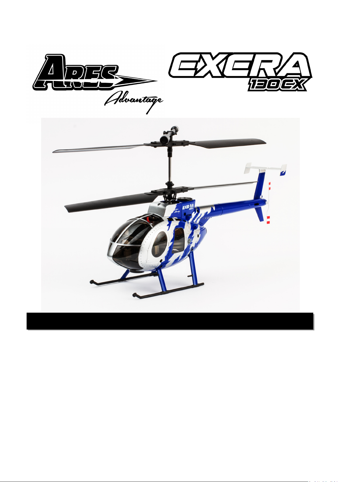
The Ares Advantage Exera 130 CX is the most advanced and easiest to y 4-channel CX heli ever! Like
other CX helis on the market it features an ultra-stable coaxial, counter-rotang blade design that helps
make ying easy. However, what sets the Exera 130 CX apart is that it includes innovave Aegis Altude
Assist Technology (AAT).
Designed and developed exclusively by Aegis engineers, AAT automacally assists in maintaining
altude above the ground and avoiding collisions with the ceiling through the use of state-of-the-
art ultrasonic sensors similar to those found in the luxury automobiles for collision intervenon
and parking assistance. The resulng benet is that AAT makes it easy for rst-me pilots to master
4-channel control and gives low-me and experienced pilots added condence to y in smaller indoor
spaces where height is limited. Plus, with the Exera 130 CX, once 4-channel ight becomes easy, you
can turn o AAT completely and sll have a great looking, great ying heli!
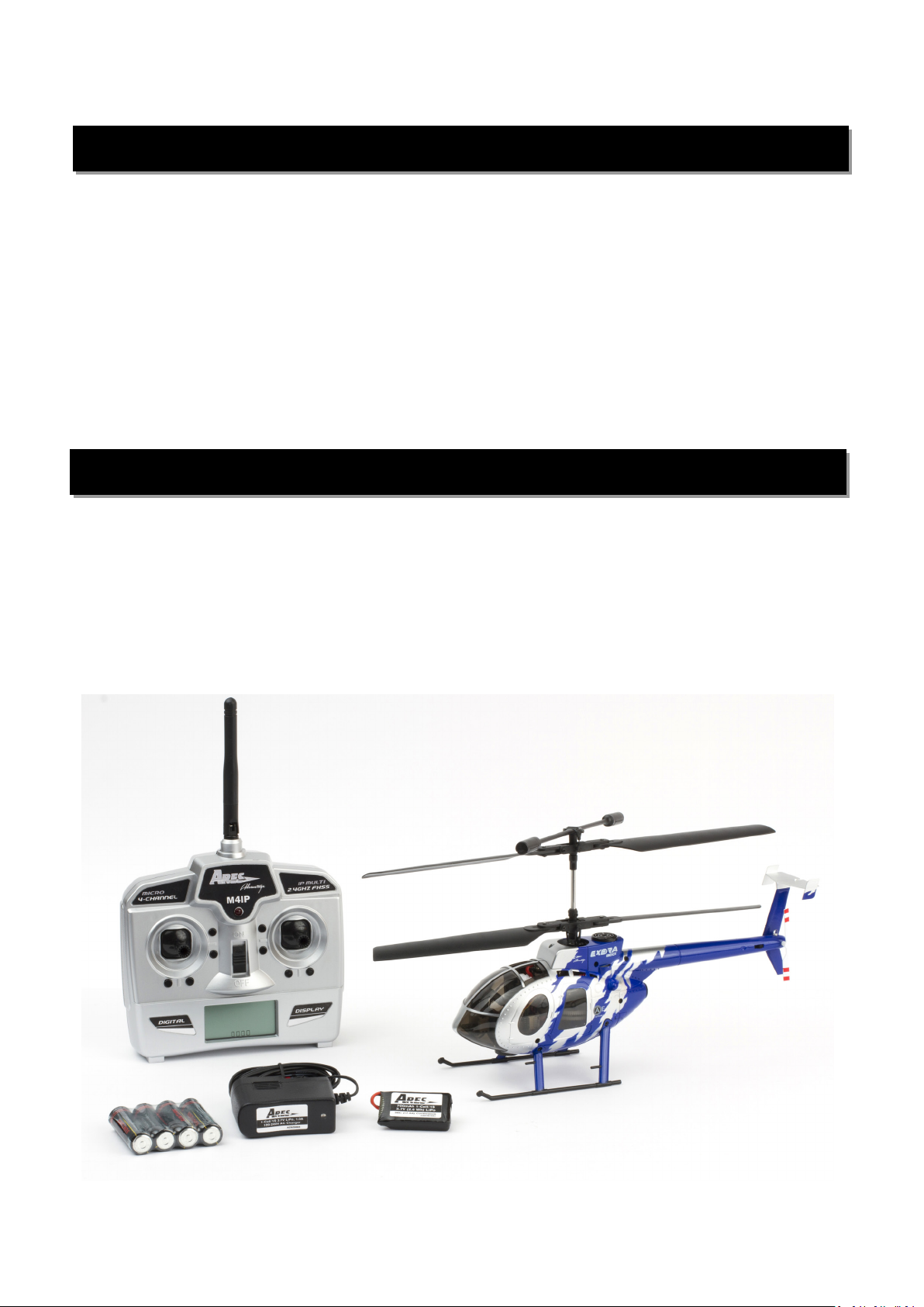
The Ares Advantage Exera 130 CX arrives 100% factory-assembled, test own and ready to y. Standard
features include a unique and durable airframe design; a highly-detailed MD 500E scale body equipped
with LED lights; a 4-channel transmier with an LCD screen, dual rates and 2.4GHz technology; a
700mAh 1S 3.7V LiPo baery and an AC charger for convenient charging from almost any outlet. Best
of all, the AAT module and ultrasonic sensors are factory-installed and ready to use with no assembly,
setup or adjustments required!
So whether you’re a rst-me pilot looking for the best heli to start with or an experienced pilot
looking to expand your skills in ght indoor spaces, innovave Aegis AAT makes the Exera 130 CX
perfect for you!

4
FCC Information
This device complies with part 15 of the FCC rules. Operaon is subject to the following two condions:
(1) This device may not cause harmful interference, and (2) this device must accept any interference
received, including interference that may cause undesired operaon.
Cauon: Changes or modicaons not expressly approved by the party responsible for compliance
could void the user’s authority to operate the equipment.
This product contains a radio transmier with wireless technology which has been tested and found
to be compliant with the applicable regulaons governing a radio transmier in the 2.400GHz to
2.4835GHz frequency range.
The associated regulatory agencies of the following countries recognize the noted cercaons for this
product as authorized for sale and use: USA
Item Descripon
Not Available Separately...................Exera 130 CX RTF Airframe
AZSZ2008M2 ....................................M4IP Micro 4-Channel IP Transmier, Mode 2
Not Available Separately...................AA Baeries (4 pcs)
AZSB7001S25J...................................700mAh 1-Cell/1S 3.7V 25C LiPo Baery, JST Connector
AZSZ2004..........................................1-Cell/1S 3.7V LiPo, 1.0A 100-240V AC Charger, JST Connector
Not Shown........................................Spare Upper and Lower Main Rotor Blade Set (1 pair each)
Exera 130 CX Contents
Calibration

5
Flight Checklist
PLEASE NOTE: This checklist is NOT intended to replace the content included in this instrucon man-
ual. Although it can be used as a quick start guide, we strongly suggest reading through this manual
completely before proceeding.
• Always turn the transmitter ON first
• Connect the LiPo flight battery to the control unit
• Allow the control unit to initialize and arm properly (on a flat/level surface)
• Fly the model (take-off from a flat/level surface)
• Land the model (land on a flat/level surface)
• Disconnect the LiPo flight battery from the control unit
• Always turn the transmitter OFF last
LiPo Battery Warnings and Usage Guidelines
IMPORTANT NOTE: Lithium Polymer baeries are signicantly more volale than the alkaline, NiCd
or NiMH baeries also used in RC applicaons. All instrucons and warnings must be followed exact-
ly to prevent property damage and/or personal injury as mishandling of LiPo baeries can result in
re.
By handling, charging or using the included LiPo baery you assume all risks associated with LiPo bat-
teries. If you do not agree with these condions please return the complete product in new, unused
condion to the place of purchase immediately.
You must charge the LiPo baery in a safe area away from ammable materials. It
is strongly suggested that when charging the baery you place it on a non-amma-
ble surface, such as a ceramic dish or ceramic le.
Never charge the LiPo baery unaended at any me. When charging the baery
you should always remain in constant observaon to monitor the charging process
and react immediately to any potenal problems that may occur.
Aer ying/discharging the baery you must allow it to cool to ambient/room
temperature before recharging.
To charge the LiPo baery use the included 1-Cell/1S 3.7V LiPo, 1.0-Amp AC Char-
ger (AZSZ2004) or a suitably compable LiPo baery charger. Failure to do so may
result in a re causing property damage and/or personal injury. DO NOT use a NiCd
or NiMH charger.
If at any me during the charge or discharge process the baery begins to balloon
or swell, disconnue charging or discharging immediately. Quickly and safely dis-
connect the baery, then place it in a safe, open area away from ammable mate-
rials to observe for at least 15 minutes. Connuing to charge or discharge a baery
that has begun to balloon or swell can result in a re. A baery that has ballooned
or swollen even a small amount must be removed from service completely.

6
Store the baery at room temperature, approximately 68–77° Fahrenheit (F), and in a
dry area for best results.
When transporng or temporarily storing the baery, the temperature range should
be from approximately 40–100°F. Do not store the baery or model in a hot garage, car
or direct sunlight whenever possible. If stored in a hot garage or car the baery can be
damaged or even catch re.
Do not over-discharge the LiPo baery. Discharging the LiPo baery too low can cause
damage to the baery resulng in reduced power, ight duraon or failure of the baery
enrely. The 1S LiPo used to power the Exera 130 CX should not fall below 3V.
The 4-in-1 control unit includes a low voltage cuto (LVC). As the low voltage level is
reached the Red LED on the tail of the 130 CX changes from blinking with a slow single
blink to a slow double blink. This combined with the reduced available power is the in-
dicaon that a baery recharge is required. Connued discharging can cause permanent
damage to the LiPo baery resulng in reduced power output and/or shortened ight
duraons during subsequent ights (or failure of the baery enrely).
Charging the LiPo Flight Battery
You must charge the included 700mAh 1-Cell/1S 3.7V 25C LiPo Baery (AZSB7001S25J) using only the
included 1-Cell/1S 3.7V LiPo, 1.0A 100-240V AC Charger (AZSZ2004) or a suitably compable LiPo bat-
tery charger. Charging the LiPo baery using a non-LiPo baery compable charger (such as a NiCd or
NiMH baery charger), or even a dierent LiPo baery charger with the incorrect sengs, may result
in damage to the baery or even re resulng in property damage and/or personal injury
When the included 120-240V AC charger is plugged into a wall socket the GREEN LED is
displayed.
Plug the 1-Cell 3.7V baery’s JST connector into the JST plug on the charger making sure that
the correct polarity is maintained. There is a small tab on the plug to assist. The LED on the
charger turns RED.
The charger is automac and when charging is complete the LED returns to solid GREEN.
Installing the Transmitter Batteries
Install the four (4) included AA baeries in the back of the transmier by rst removing the baery
compartment cover/door. Ensure proper polarity of the baeries before installing them (as noted by
the markings molded into the baery compartment), then re-install the compartment cover/door.
NOTE: If at any me the voltage indicated on the LCD screen falls below 1/2, it will be necessary to
replace the AA baeries with new ones.

7
Transmitter Details
Antenna Posion/Orientaon
The RF output signals transmit best/strongest from the sha of the antenna rather than from the p. As
a result you should never point the p of the antenna directly at the model. Also, the transmier anten-
na can be rotated up to 180° and folded up to 90° so be sure to hold the transmier and posion the
antenna as needed to ensure the best possible signal transmission.
Control/Servo Reversing
The servos are set for correct operaon from the factory. Servo reversing is available on each of the 4
channels, Throle, Rudder, Elevator, Aileron. To reverse any channel press and hold both of that chan-
nels trim buons simultaneously. In approximately 2 seconds the channel will reverse and a beep tone
will be heard. The graphic symbol on the LCD panel for that channel will indicate the change. Repeat
the process to change again. Once a channel is reversed the informaon will be retained aer the
transmier is turned o. It is unlikely that channel reversing will be necessary when using this transmit-
ter with the Exera 130 CX.
Dual Rates
High and Low control throw rates are selectable using
the throle sck. By pressing the end of the throle
sck toward its base a slight click will be felt and the
rate will toggle between High and Low. The rate select-
ed is indicated on the LCD screen in the upper right
near the baery strength indicator. Low rates are rec-
ommended when geng used to the helicopter. High
rates give more control movement and is suitable for
the more experienced pilot.

8
Flight Controls and Trimming
In the event you are not familiar with the controls of the Exera 130 CX please take the me to familiar-
ize yourself.
Throle trim buons. It is not necessary to change
the throle trims from their factory sengs.
Used to keep the nose of the helicopter
from turning to the le or right when hov-
ering. For example, if the nose of the he-
licopter turns to the right when hovering
press the le trim buon several mes unl
the nose of the helicopter stays as close to
“straight” as possible with no further rudder
control/trim input.)
Increases and decreases power to the motors
causing the helicopter to ascend or descend.
Causes the nose of the helicopter to
rotate le or right.
NOTE: It is not uncommon for the nose of most CX (coaxial) helicopters to dri slightly in one
direcon or the other throughout a ight (as the motors heat up and the baery discharges/voltage
drops). This means you may nd it necessary to adjust the rudder trim slightly throughout a ight but
typically no more than a few buon presses are necessary.

9
With the nose of the helicopter facing away
from you, pushing the sck forward will
cause the helicopter to move forward. Pull-
ing the sck backward will cause the heli-
copter to move backward
Used to help keep the helicopter from dri-
ing forward or backward when hovering. For
example, if the helicopter dris forward, press
the rear trim buon several mes unl the
helicopter stops moving forward
With the nose of the helicopter facing away
from you, moving the sck to the le will
move the helicopter le. Moving the sck
to the right will move the helicopter to the
right.
Used to help keep the helicopter from dri-
ing le or right when hovering. For example,
if the helicopter dris le, press the right
trim buon several mes unl the helicop-
ter stops moving le
Installing and Removing the LiPo Flight Battery
Aer the LiPo baery has been fully charged it’s ready to be installed in the helicopter. Open the bat-
tery hatch on the boom of the body by moving the black hatch latch towards the nose and pulling
down. Install the baery by sliding it carefully into the baery holder with the wires facing the rear.
Make sure to secure the baery plug and wires under the clip on the baery door, this keeps the wires
from contacng any of the moving parts inside the helicopter body.
To remove the LiPo ight baery (aer unplugging it) pull on the sides of the baery (NOT on the wire
leads!) while carefully holding the body out of the way to remove it from the mount/helicopter com-
pletely.

10
The Exera 130 CX is equipped with a compact and advanced 4-in-1 control unit. The control unit is a
lightweight combinaon of two electronic speed controls (ESCs), a mixer and gyro.
This checklist includes the steps you must follow to ensure proper inializaon, arming and operaon
of the control unit:
• Before each ight you must ALWAYS turn the transmier on BEFORE connecng the
LiPo ight baery to the control unit. Never connect the baery to the control unit
before powering the transmier on rst. Aer each ight you should always discon-
nect the baery from the control unit before turning the transmier o.
• The le-hand/throle sck must be set in the lowest posion in order for the con-
trol unit to arm properly. Failure to lower the sck can prevent the ESCs from arming
and/or the gyro from inializing properly. In some cases it may be necessary to also
lower the throle trim.
• Aer installing the baery in the helicopter you must be careful to ensure proper
polarity when plugging it into the 4-in-1 control unit.
Also, although the ‘JST’ connectors are ‘keyed’ to minimize the risk of a reverse polarity connecon, if
you force them it is possible to make connecon with incorrect/reversed polarity potenally causing
damage to the control unit and/or baery. When the connectors are properly aligned for correct
polarity, connecng them should require only a minimal amount of pressure to achieve the light ‘click’
that indicates secure connecon.
IMPORTANT NOTE: AFTER THE BATTERY IS CONNECTED TO THE CONTROL UNIT IT’S
IMPORTANT TO PLACE THE HELICOPTER ON LEVEL GROUND AND NOT MOVE OR ROTATE
THE HELICOPTER FOR 6 SECONDS TO ALLOW THE GYRO’S TO CALIBRATE AND ARM THE
MOTORS. If you do move/rotate the helicopter during this me it may aect inializa-
on/calibraon of the gyro which could require signicant rudder trim adjustments
and/or prevent the gyro from working during the ight. If this happens you must
disconnect the baery from the control unit and repeat the inializaon/calibraon
process.
Aer the helicopter has armed the motors use cauon as the rotor blades will now spin
with throle sck input! Do not advance/raise the throle sck unl you are clear of the
rotor blades and ready to y.
CAUTION:
Control Unit Initialization and Arming

11
Altitude Assist Technology (AAT)
IMPORTANT NOTE: Although the AAT module is ready to use right out of the box, please take the
me to read through this secon of the manual completely for informaon on funcon and perfor-
mance, before proceeding with your rst ight. Please also visit our web site at www.ares-rc.com to
watch video of the Exera 130 CX and AAT in acon.
The Exera 130 CX is equipped with innovave Altude Assist Technology (AAT). Designed and developed
exclusively by Ares engineers, AAT allows new pilots to build their skills using 3 dierent ight modes
that make the Exera 130 CX perhaps the easiest way to learn to y an RC heli ever!
Note: Ultrasound ranging is dramacally aected by the surface that is being detected. For example, a
hard surface will reect ultrasonic pulses more eecvely and result in improved detecon and rang-
ing. For best performance in Mode 1, ying over a led, linoleum, or concrete surface is recommended,
whereas ying over a carpeted surface will result in less than ideal performance.
The three modes enabled by AAT technology
include Hover Hold in Mode 1, Ceiling Avoid-
ance in Mode 2, and Direct Throle Control
in Mode 3. Using two ultrasound sensors, one
facing downward and one facing upward, the
helicopter is able to measure the distance to
the oor and ceiling, and automacally adjust
the throle depending on the mode selected.
The Exera 130 CX comes out of the box set to
Mode 1 (Hover Hold). Mode 2 and 3 can be
selected using the three-posion switch on
the tail of the helicopter.
Red LED Status Indicator
The red LED blinks rapidly when the baery is plugged in and connues during inializaon. When ini-
alized the rate changes to a slow steady blink, indicang correct inializaon and AAT funcon. If the
LED is a solid red, the control unit has inialized correctly, but the AAT module has not been detected.
An intermient short-short-pause indicates inializaon error. If this occurs, unplug the baery and re-
plug to aempt again.
AAT Functions and Performance

12
In Mode 1, the upward and downward sensors are acve to enable altude control while
avoiding ceilings and other obstacles above the helicopter.
In Mode 1, the pilot is only required to make
very basic inputs on the throle sck. With the
helicopter resng on a at, hard surface, the pilot
can move the throle sck from zero to full to
iniate take-o. The blades will then smoothly ac-
celerate, the auto-takeo feature will iniate, and
the Exera 130 CX will slowly rise to a controlled
hover between 2 and 3 feet o the ground. The
pilot is in control of all other helicopter move-
ments while the ATT Module holds the altude.
The helicopter will maintain this height unl the
pilot is ready to land. To iniate the auto-land
feature, the pilot should bring the throle sck
down to between 33% and 50%. At this point, the
helicopter will slowly descend and land smooth-
ly. Once on the ground, the throle sck should
then be moved all the way down so that the Exe-
ra 130 CX is ready for its next takeo.
If for some reason the helicopter is ying uncon-
trollably, the throle sck should be moved all
the way down so that the throle is decreased
immediately.
Flying in Mode 1
Calibration

13
In Mode 2 only the upward sensor is acve, enabling Ceiling Avoidance, which automacally re-
duces throle so that the Exera 130 CX avoids running into the ceiling
In Mode 2, the pilot has more control over throle and the AAT module performs two funcons.
First, it constantly calculates the range to the ceiling and reduces throle as necessary to avoid
possible collisions. The AAT module also monitors baery voltage and intelligently limits throle to
avoid accelerang too quickly. This funcon addresses a common mistake by rst-me pilots, where
accelerang too quickly on take-o can cause collisions.
When ying in Mode 2 beneath a ceiling composed of hard, acouscally reecve material, the
Exera 130 CX will begin to reduce throle as it moves within roughly 4 feet of the ceiling. If the
ceiling is “soer” and reects ultrasonic pulses less eecvely, this detecon range may be reduced.
CAUTION:
Please note that because the AAT Module transmits and receives ultrasound pulses through the
spinning blades, you may nd a “blind spot” where the helicopter is not able to detect objects
that are too close. The size of this blind spot varies based on ceiling material, but typically it is
8-12 inches in distance. If the helicopter does y into this space, it may no longer be able to detect
the ceiling. If that occurs, throle compensaon will stop working and the helicopter will connue
to rise if the throle is not lowered quickly.
Flying in Mode 2
Calibration

14
In Mode 3, the ultrasonic sensors are not acve and the pilot has full control of throle.
Recommended Flying Progression
Calibration
Flying in Mode 3
Calibration
First me and low me pilots should use the default seng of Mode 1. This allows the pilot to learn
the basic controls of moving the helicopter forwards/backwards, le/right, and rotang le/right with-
out needing to control the altude.
As skill improves, the pilot will want to control the altude. At this me, it is recommended to move
the mode control switch to Mode 2, which allows the pilot to control the altude with the throle sck
while sll oering unprecedented Ceiling Avoidance technology.
Once the pilot is comfortable ying in Mode 2, they can move the mode control switch to Mode 3.
In Mode 3 the AAT module is turned o, and all throle input comes directly from the pilot. The pilot
must use the throle to control the altude and avoid obstacles overhead.
Each Exera 130 CX helicopter is factory calibrated to ensure excellent performance in Modes 1 and 2.
However, due to variaons in ying environment (altude, temperature, and humidity) and the age of
baeries and motors, the helicopter may require recalibraon if the helicopter does not rise o the
ground or it rises beyond 3-4 feet in Mode 1.
Calibraon should be performed in a closed space with lile or no air movement. Fans and air condi-
oning units should be turned o, and windows should be shut. To enter calibraon mode, the pilot
should set the tail-switch in Mode 1, power on the transmier and then plug in the baery as usual.
Once the helicopter inializes, raise the throle sck to half and then quickly bring it down to zero
again. Then, quickly toggle the tail switch back and forth from posion 1 to posion 3 ve mes ending
up in posion 1. Upon successfully entering calibraon mode, the user will hear two quiet, high fre-
quency “chirping” sounds, which will indicate that the helicopter is in calibraon mode.

15
Note: Once in calibraon mode the helicopter will y as if it is in Mode 3 with no AAT Funcon, even
though the tail switch indicates Mode 1. This is normal and indicates that you have successfully en-
tered the calibraon mode.
To perform calibraon, hover the helicopter in place for 4 minutes. It is important to hover the helicop-
ter as smoothly as possible, maintaining a steady height with minimal control input. Aer 4 minutes,
land the helicopter and immediately unplug the baery. The Exera 130 CX will now be recalibrated to
account for aged motors and baery as well as the pilot’s ying environment. To avoid incorrect
calibraon, inexperienced pilots may wish to ask a more experienced pilot to help them.
The eecveness of ultrasonic ranging is heavily dependent on the surface that is being measured.
Hard, reecve surfaces reect ultrasonic pulses well and therefore result in increased sensing dis-
tance. On the other hand, soer, more acouscally absorbent materials signicantly reduce sensing
distance. In parcular, performance in Mode 1 over carpet, furniture, or other so materials will result
in degraded performance.
Devices using ultrasonic ranging can interfere with one another if operated in close proximity. There-
fore, it is important that mulple Exera 130 CX helicopters in modes 1 and 2 not be own within 30 feet
of each other.
Ultrasonic sensors (transceivers) generate sound waves around 40kHz. These sound waves can disturb
some animals, including dogs. We recommend that you avoid ying the Exera 130 CX around dogs as
doing so may cause them to behave erracally.
Selecting a Flying Area
Calibration
The Exera 130 CX is a micro class helicopter designed for indoor ying spaces, such as a living room, ga-
rage, or gymnasium. You’ll want to select an open area free of people and obstrucons. We suggest an
area with at least 12-feet by 12-feet of oor space and no less than 8-foot ceilings when making your
rst few ights.
Aer you’ve properly trimmed the helicopter and become familiar with its handling and capabilies
you may be able to y in other smaller and less open areas, but it’s always more fun to y indoors in
spaces that are larger and more open when possible.
Notes on Ultrasonic Ranging

16
Flying Tips
Calibration
Now that you’ve selected a suitable ying area you’re ready to y! And when making your rst ights
we suggest following these steps:
• Slowly raise the throle sck to increase the speed of the main rotor blades unl
the model begins to li o. Do NOT raise the sck too quickly as the model could
climb too fast.
• When trying to move the helicopter around, make small inputs on the control
scks and don’t hold an input for too long. A common mistake is when too much
control input is given.
• You’ll nd that it somemes takes minor throle adjustments to maintain altude
in a hover. Remember to keep these adjustments as minimal as possible as large ad-
justments could result in a loss of control and/or a possible crash.
• While aempng to establish a low-level hover out of ground eect (approxi-
mately 20–24 inches high or higher) you can check to see if any trim adjustments are
required to help keep the helicopter from constantly driing in various direcons. If
you nd that the helicopter constantly dris without any direconal control input it
may be best to land the model before making any adjustments to the trim sengs
using the trim levers on the transmier (you can nd more informaon regarding the
locaon and funcon of the trim levers in the ‘Flight Controls and Trimming’ secon
of this manual).
• Connue to pracce unl you’re comfortable hovering the helicopter and con-
trolling it in Mode 1. Then you can transion to Mode 2 for more altude control.
• If at any me during ight you feel like the helicopter is driing out of/beyond
your control, simply release all of the controls except for throle. The throle will
be needed to maintain altude, but due to the inherent stability of the coaxial,
counter-rotang blade design, releasing all of the other controls will allow the heli-
copter to return to a stable hover on its own.
Note: Crash damage is not covered under warranty.
• Once you’ve gained the experience and condence in hovering your helicopter you
can aempt more advanced maneuvers including:
Forward Flight
Backward Flight
Pirouees
Skidding Takeos
Skidding Landings
Spot Landings

17
Replacement Parts List
Exploded View
Reference # Item Number Descripon
Not Shown AZSZ2000 Exera 130 CX Ultra-Micro RTF, MD 500E
4 AZSB7001S25J 700mAh 1-Cell/1S 3.7V 25C LiPo Baery, JST Connector:
Not Shown AZSZ2004 1-Cell/1S 3.7V LiPo, 1.0A 100-240V AC Charger, JST:
22 AZSZ2006 4-in-1 Control Unit, Rx/ESCs/Mixer/Gyro: Exera 130 CX
21 AZSZ2007 2.4-Gram Servo (5W): Exera 130 CX
7 AZSZ2007AS 2.4-Gram Servo (5W) Arm Set: Exera 130 CX
Not Shown AZSZ2007GS 2.4-Gram Servo (5W) Gear Set: Exera 130 CX
Not Shown AZSZ2008M2 M4IP Micro 4-Channel IP Transmier, Mode 2: Exera 130

18
Reference # Item Number Descripon
30 AZSZ2010 Altude Assist Technology (AAT) Module/Unit
Not Shown AZSZ2011 Altude Assist Technology (AAT) Wire Lead/Cable
26 AZSZ2012 Altude Assist Technology (AAT) Mode Selecon Switch
28 AZSZ2013 Altude Assist Technology (AAT) Sensor and Mount Set
Not Shown AZSZ2014 Altude Assist Technology (AAT) Sensor Mounts
20 AZSZ2015 Motor with Shallow Pinion Gear (Front): Exera 130 CX
10 AZSZ2016 Motor with Deep Pinion Gear (Rear): Exera 130 CX
17 AZSZ2017 Inner Sha with Head/Hub: Exera 130 CX
12 AZSZ2018 Outer Sha: Exera 130 CX
23 AZSZ2019 Inner and Outer Main Gear Set: Exera 130 CX
9 AZSZ2020 Inner Sha Bearing Holder W/Outer Sha Retaining Collar
5 AZSZ2021 Bearing, 1.5x4x2mm (2pcs): Exera 130 CX
6 AZSZ2022 Bearing, 3x6x2.5mm (2pcs): Exera 130 CX
11 AZSZ2023 Swashplate: Exera 130 CX
19 AZSZ2024 Lower Rotor Head Linkage and Servo Push Rod Set
18 AZSZ2025 Lower Rotor Head/Hub: Exera 130 CX
16 AZSZ2026 Stabilizer Flybar Set with Linkage: Exera 130 CX
13 AZSZ2027 Main Rotor Blade Grip Set (1 pair): Exera 130 CX
14 AZSZ2028 Lower Main Rotor Blade Set, B (1 pair): Exera 130 CX
15 AZSZ2029 Upper Main Rotor Blade Set, A (1 pair): Exera 130 CX
8 AZSZ2030 Main Frame Set: Exera 130 CX
2 AZSZ2031 Hardware/Screw Set: Exera 130 CX
25 AZSZ2032 LED Light Set: Exera 130 CX
24 AZSZ2033 MD 500E Baery Hatch Set: Exera 130 CX
1 AZSZ2034 MD 500E Landing Gear/Skid Set: Exera 130 CX
29 AZSZ2035 MD 500E Top Cover: Exera 130 CX
3 AZSZ2036 MD 500E Body Side Set: Exera 130 CX
31 AZSZ2037 MD 500E Windshield: Exera 130 CX
27 AZSZ2038 MD 500E Tail Fin Set: Exera 130 CX
Separate AZSZ2039 MD 500E Tail Rotor: Exera 130 CX

19
30-Day Limited Warranty Term Period:
We warranty that the Product(s) purchased (the “Product”) will be free from defects in materials and work-
manship when the product is new (before being used) for the limited warranty term period, 30 days, from the
date of purchase by the Purchaser.
If you believe a defect in material, workmanship, etc. was not apparent when the Product was new and
only became evident after the Product was used, take the following steps. If you purchased the Product at
a HobbyTown store, please contact your local HobbyTown store for warranty support and/or service. If you
purchased the Product from the Firelands website, use the contact information found under the Support
heading to contact Firelands directly.
If you contact Firelands, you may be asked to send the product to Firelands, at your cost, for inspection.
Provided the warranty conditions have been met within the warranty term period, the components that are
found to be defective, incorrectly manufactured or assembled may be repaired or replaced, at the sole
discretion of Firelands. Your warranty item will be returned to you at Firelands’ expense. In the event your
product needs repair or a replacement part that is not covered by this warranty, your local HobbyTown store
or Firelands can assist you with support and in obtaining the genuine replacement parts to repair your Prod-
uct. Firelands will charge $40.00 per hour plus the cost of replacement parts to service your vehicle if after
contacting you, you so authorize such repairs. Your product will be returned to you at your expense.
If you purchased your Product from a HobbyTown Internet site not afliated with a local store, please consult
that site for its support and service policies. You can also nd more information at
www.Hobbytown.com., by emailing customerservice@relandsgroup.com or call 800-205-6773
Warranty, Support and Service

20
www.Ares-RC.com
© 2013
Table of contents
Other Ares Advantage Toy manuals
Popular Toy manuals by other brands

rego DESIGN
rego DESIGN McLaren Senna GTR 42123 installation guide

Excalibur
Excalibur Wasp Indoor/Outdoor Helicopter 8632 instruction manual

BCP
BCP SKY5060 instruction manual

GREAT PLANES
GREAT PLANES Hellcat ARF instruction manual

Lionel
Lionel Mobil owner's manual

Amewi
Amewi DRF AFX-135 PRO Brushless Operation manual