Ultimate jets Diamond User manual

Ultimate Jets - Diamond assembly manual - Revision 4 -01/01/2015
1
Diamond
Assembly manual
Revision 4

Ultimate Jets - Diamond assembly manual - Revision 4 -01/01/2015
2
8190 Barker Cypress,
Suite #300,
Cypress, Texas, 77433
Phone: 281-855-9154
www.ultimate-jets.net

Ultimate Jets - Diamond assembly manual - Revision 4 -01/01/2015
3
INTRODUCTION
The Diamond is our new performance jet. It is fully composite, delivered assembled and painted.
It was designed for advanced jet pilots with following objectives :
-Very easy to fly.
-Short take off and landing due to custom designed laminar airfoil, large flaps and low wing loading
-Very fast assembly
-Easy access to engine (big side engine hatch)
-Easy access to fuel tank, ECU and radio with a large fuselage canopy hatch
-Easy battery access with removable nose section and reinforced carbon fiber servo covers
It is designed for a 160 to 220 N thrust turbine.
The model comes finished, fully molded in composite material and painted in the molds. All the bulkheads
are glued. All control surfaces are hinged. No gluing is required. This model has plug in wings, fin and
stabilizers as well as removable nose cone and nose tray for easier transport.
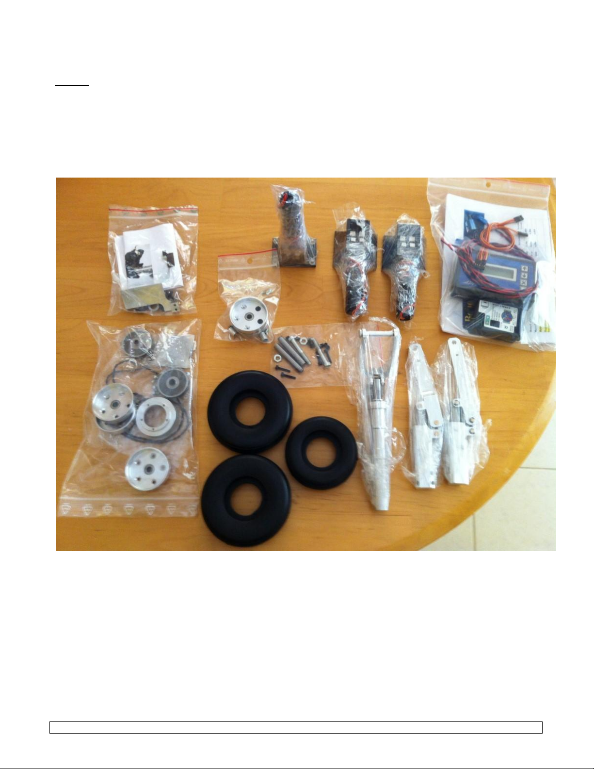
All necessary hardware is included in the box.
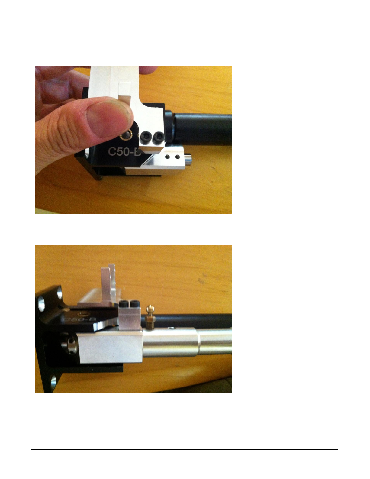
The assembly only requires a few hours to fit the engine and the remote control components.
The Diamond ARF model includes :
- High quality epoxy-glass fuselage painted.
- All plywood and wood parts premounted.
- Fully molded wings, stabs and fin painted
- Two aero grade aluminum wing tube.
- Access hatch and canopy requiring no additional work.
- All hardware (screws, servo cover, ...)
- Instructions in English with pictures.

Ultimate Jets - Diamond assembly manual - Revision 4 -01/01/2015
4
Parts required to complete the kit :
-5 liters kevlar fuel cells
-Deluxe pneumatic retractable landing gear with special CNC
oleo legs and wheels set on bearing + brakes
-Deluxe electric retractable landing gear with special CNC oleo
legs and wheels set on bearing + brakes
-
-Stainless steel exhaust pipe
- Clear canopy with carbon fiber cap
- Resin instrument panel

Ultimate Jets - Diamond assembly manual - Revision 4 -01/01/2015
5
- LCD instrument panel
- Molded baquet seat
- Plastic molded 1/3 size pilot
- Scale 1/3 size pilot
- Wings, rudders, stabs protection covers

Ultimate Jets - Diamond assembly manual - Revision 4 -01/01/2015
6
DISCLAIMER
Ultimate Jets assumes no liability for the operation and use of these products.
The owner and operator of these products should have the necessary experience and exercise common
sense. Said owner and operator must have a valid Model Airplane license/ waiver and insurance as
required.
Assembly Instructions
Installation of the remote control equipment
Components needed:
Elevator: two, JR 8711 25 kg torque servos.
Rudder: one JR 8711 25 kg torque servos.
Ailerons: two JR 8711 25 kg torque servos
Flaps: two JR 8711 HV 35 kg torque servos
Steering nose wheel: one 8 kg torque servo
Receiver and switch
Remote control and ECU batteries

Ultimate Jets - Diamond assembly manual - Revision 4 -01/01/2015
7

Ultimate Jets - Diamond assembly manual - Revision 4 -01/01/2015
8
Gear:
Please, use only the special Behotec C-50 landing gear set supplied by Ultimate Jets.
If you use standard oleos, you will have to modify the gear position and gear cut in the wings. This is a
very delicate job as the room available in the thin wing is very limited.
Assemble the gear according to the Ultimate Jets Behotec e-tract gear assembly manual. The pneumatic
gear assembles the same, thus the same manual is relevant for this job.

Ultimate Jets - Diamond assembly manual - Revision 4 -01/01/2015
9
install the main gear on the wing plywood mounts.
Fasten each gear with four 5x16 mm socket head screws.
Connect all gear tubing or E-Tract electrical loom as described in the gear manual.
Fit the brake tubings/ brake loom and attach them with tie wraps or stainless steel safety wire.

Ultimate Jets - Diamond assembly manual - Revision 4 -01/01/2015
10
Locate the steering servo mount accessories bag and open.
Install the servo bracket on the side of the trunion as shown on the picture below. The two socket head
screws will require firm fastening to ensure that the bracket does not move when the servo is operating.
Install the brass ball on up most the set screws holes of the strut and insert the strut into the shear pin.
Fasten with thread lock and install the other set screws to secure the strut.
The servo bracket is set for standard JR servo size of 39.8 mm. For Futaba standard servo, you will have to
trim the bracket by 0.2 mm. Use an electric file or a tungsten carbide rotary file for this job.
Once the servo is installed, setup the pushrod by installing the two ball links on the threaded rod and
trimming it to the appropriate length.

Ultimate Jets - Diamond assembly manual - Revision 4 -01/01/2015
11
The servo arm ball link should be set at the second hole from the center. Check the arm travel does not
push any of the two ball links out of their respective balls. Also make sure that the link stays flat on its ball
Fit the front gear on the vertical bulkhead of the plywood nose structure.
Fasten the front gear with four 5x16 mm socket head screws and blind nuts.

Ultimate Jets - Diamond assembly manual - Revision 4 -01/01/2015
12
Elevator servos :
We recommend the use of a high quality digital servo of at least 200 oz.in for the elevator. The JR 8711 is
our preferred choice for this control. Here is the flight control simulation for the elevator.
Fit a high quality aluminium arm on the servo spline. Install the supplied 4-40 HD ball link on the arm
with a countersink screw and thin nut. Trim any screw thread excess to make the arm/ ball/ screw head
assembly as thin as possible.
Install the servos in the carbon fiber Ultimate Servo Covers with the provided #6 sheet metal screws. A
spacer might be required to place the servo arm/ ball link/ screw assembly exactly centered in the carbon
fiber funnel. the clearance should be 0.5 mm , evenly split both sides. Apply thread lock fluid.

Ultimate Jets - Diamond assembly manual - Revision 4 -01/01/2015
13
Place the carbon fiber cover in the appropriate slot on the stabilizer.
Drill four 1 mm holes in the wings for the cover screws position. Check holes position.
If OK, drill the carbon cover at 2.5 mm and the wing pocket at 1.8 mm. Countersink the cover screw holes.
We recommend our 6 flute carbide tool to cut the countersunk hole through carbon fiber.
http://www.ultimate-jets.net/collections/machining-hardware
Secure on the elevator with the appropriate countersink screws.
Locate the elevators control horns. Detach from the machined plate and prepare. The gluing surface should
be scuffed off and drilled.
Check the CNC machined slot in the control surface. It should allow a good clearance around the horn
fiber for a good bond. Verify the alignment with the pushrod out of the servo hatch. Enlarge/ modify if
necessary.
Protect the slot with some tape and glue the horn with Hysol E-20HP.
Connect two of the supplied 4-40 mm HD ball links to the 4-40
threaded rod.
Fasten the servo cover with the supplied #2 screws.
Connect the servo to the control horn.
Apply thread lock.
Make a slot in both stabilizers at the root between the main tube and the rear anti rotation pin to pass the
servo plug through.
Glue the anti-rotation aluminum pins in the stabilizers with Hysol E-20HP. Make sure that the pins extend
from the root by 10 mm.

Ultimate Jets - Diamond assembly manual - Revision 4 -01/01/2015
14
Aileron and flap servos :
We recommend the use of a high quality digital servo of at least 200 oz.in for the ailerons. The JR 8711 is
our preferred choice. Here is the aileron simulation:
The flaps need a more powerful servo of at least 300 oz.in. We recommend the JR 8711HV.
Maximum speed for takeoff flaps is 115 mph:

Ultimate Jets - Diamond assembly manual - Revision 4 -01/01/2015
15
Maximum speed for landing flaps is 80 mph:
Fit a high quality aluminium arm on the servo spline. Install the supplied 4-40 HD ball link on the arm
with a countersink screw and thin nut. Trim any screw thread excess to make the arm/ ball/ screw head
assembly as thin as possible.
Install the servos in the carbon fiber Ultimate Servo Covers with the provided #6 sheet metal screws. A
spacer might be required to place the servo arm/ ball link/ screw assembly exactly centered in the carbon
fiber funnel. the clearance should be 0.5 mm , evenly split both sides. Apply thread lock fluid.

Ultimate Jets - Diamond assembly manual - Revision 4 -01/01/2015
16
Place the carbon cover in the appropriate slot on the wing.
Drill four 1 mm holes in the wings for the cover screws position. Check holes position.
If OK, drill the carbon cover at 2.5 mm and the wing pocket at 1.8 mm. Countersink the cover screw holes.
We recommend our 6 flute carbide tool to cut the countersunk hole through carbon fiber.
http://www.ultimate-jets.net/collections/machining-hardware
Check securing with the provided #2 countersink screws and remove.
Locate the flap and aileron control horns. Detach from the machined plate and prepare. The gluing surface
should be scuffed off and drilled as per the pictures below.

Ultimate Jets - Diamond assembly manual - Revision 4 -01/01/2015
17
Check the CNC machined slot in the control surface. It should allow a good clearance around the horn
fiber for a good bond. Verify the alignment with the pushrod out of the servo hatch. Enlarge/ modify if
necessary.
Flaps control horn
Aileron control horn

Ultimate Jets - Diamond assembly manual - Revision 4 -01/01/2015
18
Glue the control horns in position with Hysol E-20HP.
Aileron control horn Flap control horn
Connect two of the supplied 4-40 mm HD ball links with the 4-40 threaded rod.
Fasten the servo cover with the supplied #2 screws.
Connect the servo to the control horn.
Apply thread lock.

Ultimate Jets - Diamond assembly manual - Revision 4 -01/01/2015
19
Make an oval hole in the wing root for the 12 way Ultimate Servo Connectors. The hole should be big
enough to clear the female plug base that will be fastened on the fuselage root.
Install the wing loom as per the diagram below ( the blue line is the gear loom ):
Make a square hole in the fuselage the USC female plug. Make sure to align the plug with the oval hole
previously made in the wing.
Fasten the female plug with two sheet metal screws.

Ultimate Jets - Diamond assembly manual - Revision 4 -01/01/2015
20
Rudder servo:
We recommend the use of a high quality digital servo of at least 200 oz.in for the rudder. The JR 8711 is
our preferred choice for this control. Here is the flight control simulation:
Table of contents
Other Ultimate jets Toy manuals
Popular Toy manuals by other brands

Amewi
Amewi TORNADO manual

Jamara
Jamara VW Golf GTI 2,4 GHz Instruction

V-tech
V-tech Talking Whiz Kid Power Mouse user manual

Mattel
Mattel Nickelodeon Blaze and the Monster Machines quick start guide

Educational Insights
Educational Insights Elliott the Musical Teaching Bear manual

Multiplex
Multiplex ROXXY BL-Control 715 S-BEC operating instructions

AeroWorks
AeroWorks ULTIMATE 20-300 ARF-QB Assembly manual

The Learning Journey
The Learning Journey Techno Gears Marble Mania Velocity 2.0 instruction manual

Fisher-Price
Fisher-Price PLAYMYWAY R4567 user manual

FISCHER
FISCHER Fischertechnik AIRCRAFT BASIC manual

ICM Controls
ICM Controls I-153 manual

LEGO
LEGO 6137 manual