ARG ARG-OM-024 User manual

ARG-OM-024
PVS Controller
Manual & User Guide
FITNESS ENTERTAINMENT SOLUTIONS
www.argaudio.com
4
4
0
R
a
ms
la
n
d
Ave
H
anna
f
ord
,
ND 5844
8
888.468.4552
-OM-
0
24
www.argaudio.co

Audio Resource Group, Inc.
Page 1
www.argaudio.com
PVS CONTROLLER MANUAL
Audio Resource Group 440 Ramsland Ave P.O. Box 39 Hannaford, ND 58448 888.468.4552 ©2012 Audio Resource Group, Inc. All Rights ReservedARG-OM-024
PVS Controller Diagram
1. Input Button
(Press to change the input source)
2. Power Button
(Press to turn the PVS ON or OFF)
3. Channel UP Button
4. Channel DOWN Button
5. Volume UP Button
6. Volume DOWN Button
7. Back Button
(Press to go the last channel viewed)
8. Numbers 0 to 9
(Press to enter channel numbers)
9. Decimal Button
(Press to select digital sub-channels)
10. Enter Button
(Press to enter selection)
11. RJ45 Connector
(Use to connect cable to back of PVS)
12. 3.5mm Stereo Audio Jack
(Use to connect headphones)
The ARG remote controller is designed to be mounted with most makes and models of cardio
equipment. To mount the control unit, first slide the cable ties through the appropriate holes in the
mounting bracket on the underside of the controller: top to bottom if mounting it to a horizontal bar
(Figure 1); side to side if mounting to a vertical bar (Figure 2).
INSTALLING AND MOUNTING THE CONTROLLER:
Figure 1: Figure 2:
Wrap the cable ties around one of the bars on the equipment in an appropriate position. Take note
how the equipment will be used and make sure the placement of the controller will not interfere with
the function or the range of motion of the equipment.

Audio Resource Group, Inc.
Page 2
www.argaudio.com
Audio Resource Group 440 Ramsland Ave P.O. Box 39 Hannaford, ND 58448 888.468.4552 ©2012 Audio Resource Group, Inc. All Rights ReservedARG-OM-024
PVS CONTROLLER MANUAL
Pull the cable ties tightly around the bar so that the controller does not rotate (figure 3). Cut the ends
of the ties to eliminate excess (figure 4). (Note: A typical treadmill installation is shown below for
reference; controller placement will vary dependent upon equipment.)
Connect one end of the coiled CAT-5 cable to the RJ-45 terminal located on the underside of the
remote control unit (figures 5 and 6). The other end should be plugged into the terminal marked RJ45
on the PVS. Earlier models of the PVS were not labeled. If using an older unit, find the RJ45 plug on
the TV to connect the cable.
Figure 3: Figure 4:
Figures 7 and 8 show final placement of controller.
Figure 5: Figure 6:
Figure 7: Figure 8:
The ARG PVS controller does NOT need to be programmed to work with the PVS. When all of the
connections are made, run through the functions of the controller and make sure the PVS responds
appropriately. If everything works correctly, the system is ready to use. If the PVS does NOT respond
to the input from the controller, unplug the PVS from the power source for one minute. Re-connect
the power and turn the PVS back on to re-initialize the system. This will synchronize the display with
the remote control unit and establish communication. If problems persist, contact your dealer or call
ARG technical service for assistance.

Audio Resource Group, Inc.
Page 3
www.argaudio.com
PVS CONTROLLER MANUAL
Audio Resource Group 440 Ramsland Ave P.O. Box 39 Hannaford, ND 58448 888.468.4552 ©2012 Audio Resource Group, Inc. All Rights ReservedARG-OM-024
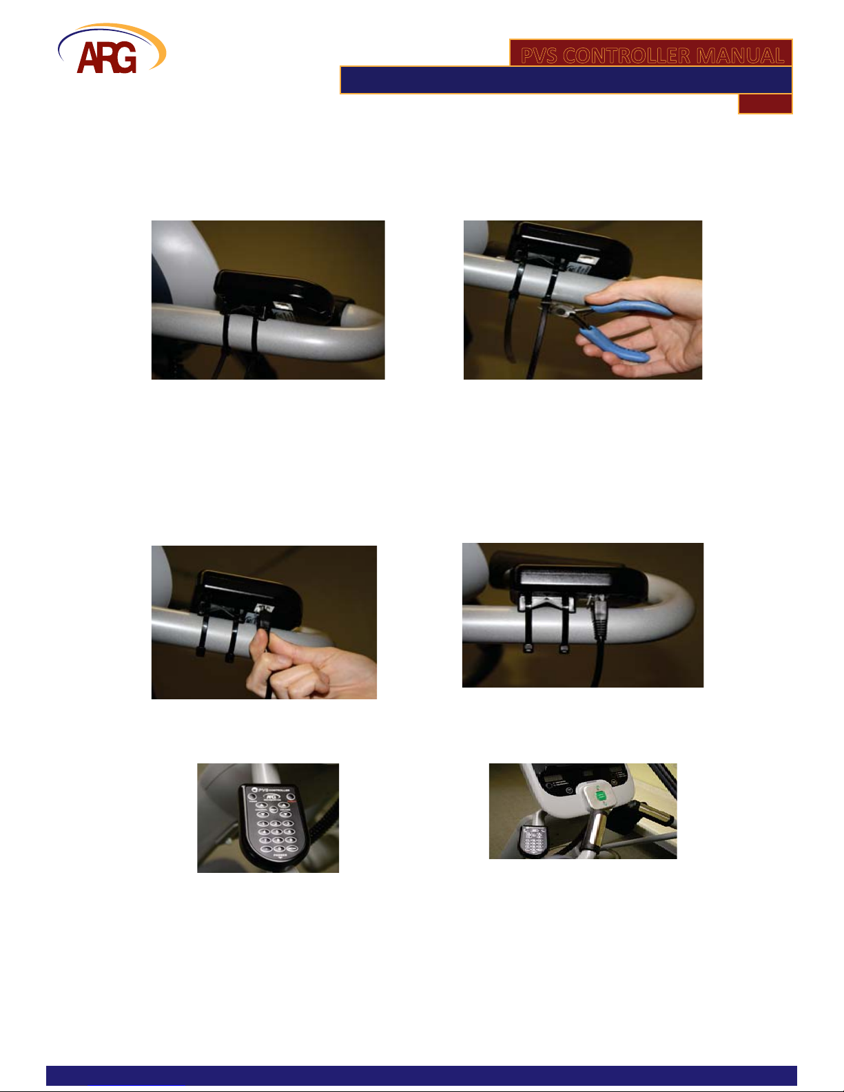
HEADPHONE JACK REPLACEMENT:
Due to heavy use, it is normal for the contacts in the headphone jack assembly to wear out over
me. The ARG 2.4GHz receiver is equipped with a replaceable headphone jack module to resolve
this problem without replacing the enre unit. Under IDEAL condions, the headphone jack is rated
to last approximately 6,000 plug inserons and removals (cycles). The headphone jack module can,
in most cases, be changed without removing the receiver unit from the cardio machine.
1. To remove the worn jack, locate the “arrow” on the tab of the jack module located on the
back side of the receiver toward the boom.
2. Press on the “arrow” and slide the module in the direcon of the “arrow”.
3. To install the new module, guide the grooves of the jack module into the tabs of
the receiver.
4. Push the module back into the receiver unit unl it “clicks” into place.
WARRANTY
Audio Resource Group, Inc. provides TWO years warranty from the purchase date on controllers. During the
warranty period, if the material and workmanship is determined to be defecve by our repair center, ARG will:
(1) repair the product with new or rebuilt parts; or
(2) replace the product at no charge with new or rebuilt comparable products or parts
This warranty does not cover cosmec damage of the product or if the serial number or model number axed to
the product has been removed, defaced, changed, altered or tampered with. This warranty does not cover
installaon or signal recepon problems.
Warranty only applies to the original buyer. Warranty is void if products have been damaged due to modicaon,
repair, or misuse by unauthorized personnel. ARG, Inc. is not liable, without limitaon to any person or enty, for
any direct, incidental, consequenal damages or medical expenses caused by any use, defect, failure or malfuncon
of the product. The terms of the warranty are governed by the laws of the state of North Dakota, USA.
ARG will only accept returned products with prepaid shipping and a return authorizaon number. Contact ARG,
Inc. at 888-468-4552 for a return authorizaon number or for addional informaon.
MAIL to: SHIP to:
ARG, Inc. ATTN: Repair Department ARG, Inc. ATTN: Repair Department
PO Box 39 440 Ramsland Avenue
Hannaford, ND 58448 Hannaford, ND 58448
Phone: 888-468-4552 Fax: 888-373-4819 Phone: 888-468-4552 Fax: 888-373-4819
Table of contents