ariazone 5001 User manual

1
ARIAZONE 5001 FULLY AUTOMATIC REFRIGERANT PROCESSOR
OPERATORS MANUAL
Contents Page
1. Introduction......................................................................................................... 2
2. Safety ................................................................................................................. 3
3. Technical Features ............................................................................................. 4
4. Displays Descriptions ......................................................................................... 5
5. Ariazone 5001 Main Parts & Features ................................................................ 6
6. Preparing the machine for use ........................................................................... 8
7. Printer (if fitted) ...................................................................................................10
8. Cylinder filling procedure ................................................................................... 12
9. Connecting Ariazone 500-1FA to the A/C system ............................................. 13
10. Step by Step Servicing Procedure ................................................................... 14
10.1. Recovery & Recycling Mode ......................................................................... 14
10.2. Evacuation Mode ...........................................................................................16
10.2a. Leak testing (vacuum)…………………………………………………………...16
10.3. Oil or UV dye Injection Mode ........................................................................ 17
10.4. Refrigerant Charge Mode ............................................................................. 18
11. One Cycle Servicing Procedure ....................................................................... 19
11.1. Conditions that will prevent automatic cycle procedure ................................. 21
12. Cylinder Air Purge ............................................................................................ 22
13. Unit Service Procedure .................................................................................... 23
15. Unit Calibration Procedure ............................................................................... 24

2
1. Introduction
The Ariazone 5001 - Fully Automatic system is a user-friendly tool specifically designed for the
automotive air-conditioning technicians, to carry out the following functions:
-Testing air conditioning system
-Recover and recycle refrigerant.
-Electronically gauge amount of refrigerant recovered from air-conditioning system.
-Electronically gauge amount of oil removed from air-conditioning system (if any).
-Evacuate air-conditioning system.
-Leak test air-conditioning system (under vacuum).
-Electronically charge lubricating oil or UV dye by volume into the air-conditioning system.
-Electronically charge refrigerant by weight.
The Ariazone system is a microprocessor control system. This provides electronically controlled
functions, whilst keeping the operator constantly informed and in full control.
This unit has been designed and build with high level of reliability including maximum safety for
the operator. The operator needs only to be responsible for the proper use and maintenance of
the unit, in accordance with the manufacturer instructions found in this manual.
This manual contains important information pertinent to operator safety, and must accompany the
unit, in the case of sale or transfer to another party.
Ariazone International reserves the right to modify this manual and the unit itself at any time
without prior notice.
Environmental information
This product may contain substances that can be hazardous to the environmental or to human health if it's
not disposed of properly.
Electrical and electronic equipments should never be disposed of in the usual municipal waste, but must be
separately collected for their proper treatment (recycling).

3
We also recommend that you adopt appropriate measures for environmental protection: recycling of the
internal and external packaging of the product, including batteries (if any).
With your help it is possible to protect our planet and improve the quality of life, by preventing potentially
hazardous substances being released in to our environment.
2. Safety
Ariazone 5001 unit is extremely simple and reliable in selecting and performing all it’s functions.
Therefore, the user is not exposed to any risk, if the general safety guidelines reported below are
followed, in association with proper use and maintenance of the unit.
-Read this user manual carefully before operating the unit. If you do not understand any
section of this manual, please contact Ariazone International direct or your nearest Ariazone
distributor.
-This equipment is to be operated by accredited technician only! Users must have basic
knowledge of air-conditioning and refrigeration systems, including potential hazards
associated with the handling of refrigerants and systems under high pressure.
-Handle refrigerant with care as serious injury may occur. Always wear appropriate
protective clothing and safety glasses.
-Avoid inhalation of the refrigerant. Use only in well ventilated work areas.
-Use only R134a refrigerant with this equipment.
- Do not expose the machine to direct artificial heat or rain.
-Do not tamper with or change safety control devices or their settings.
-The power cable may only be connected to a socket with nominal voltage stated on
the rating plate, located at the rear of the unit.
-Power lead plug to be connected only to power point with an earth.
-When transporting the unit keep upright and remove refrigerant cylinder from platform.
-Never operate the equipment with a damaged power lead, replace it immediately.
-Before removing any protective cover from unit, always unplug power lead from power point.
-Maintenance is to be carried out as per the manufacturer recommendation shown in this
manual. Only Ariazone approved parts are to be used for maintenance and repairs.

4
3. Technical Features
Refrigerant .......................................... R134a
Electronic refrigerant scale ..................+/- 10 g resolution
Load cell ............................................. 60kg with 150% overload capacity
LP and HP gauges ..............................AI-D 68 mm kl.1.0
Recovery cylinder ................................12 kg (25kg on heavy duty model)
Recovery pump ................................... AI-FR11G, 275W
Recovery rate ...................................... 380 g/min (liquid state)
Vacuum pump ......................................2 stage, 75 l/min, (140 l/min available on request)
Vacuum ................................................5 x 10-1 Pa
Filter dryers (main) ...............................AI 162-1/4" (x 1)
Filters dryer (primary)…………………...AI 032-1/4" (x 2)
Dimensions ...........................................W- 580 mm, (23”) D- 620 mm (24,1/2”) H-1090 mm (43)
Weight .................................................. 75 kg (180lb)
Chassis ................................................ Sturdy all steel construction powder coated.
Supply voltage ..................................... 230V/ 50Hz (110V/ 60Hz available on request)
Noise level ............................................< 70 dB (A).
Fixed wheels……………………………..200mm (8”) Heavy duty oil resistant
Caster wheels…………………………....75mm (3”) Heavy duty oil resistant

5
4. Display descriptions
HIgH PrES - Excess pressure in refrigerant cylinder
TArE - Calibrating the weight display to read -0.00 with an empty cylinder on platform.
TAr1 - Calibrating 0.00 on recovered oil vessel
TAr2 - Calibrating 0.00 on new oil vessel
SPAn - Calibrating of the refrigerant electronic scale
SPn1 - Calibrating of the recovered oil vessel electronic scale
SPn2- Calibrating of the new oil vessel electronic scale
Err1 - Disconnected load cell lead or faulty load-cell.
CYL FULL - Refrigerant weight exceeds maximum allowable limit and will not recover any more
refrigerant
nO rEF - No refrigerant pressure in service hoses, or manifold hand valves are not open
dOnE - The selected function is completed
FILT 99Hr - Displays filter life in number of hours when machine is switched on
PAUS - Recovery pause is running, for duration of three minutes.
bUSY - Purge solenoid opens to cylinder vapour port to pressurize oil separator
CYL - This display allows the operator to set the maximum allowable refrigerant weight in
cylinder.
OIL FULL - Operator should empty the oil vessel and press "STOP
ADD OIL - Operator should fill the new oil vessel.

6
5. Ariazone 5001 FA Main Parts & Features
1. Analog gauges - Two large analogue gauges display suction and discharge pressures, which
are mounted on the front panel for easy viewing by the operator.
Pressures are displayed in Bar & PSI and temperatures in degrees Celsius.
2. Display -A three digit led display indicates refrigerant weight in kg. or lb., depending
upon the user selection. A heavy-duty load cell located under the cylinder platform is
used to perform these measurements.
Led enunciators above and below the numeric display inform the operator of the
units of display and whether the display is indicating the weight of refrigerant currently
within the cylinder, the amount of refrigerant being charged or the amount of
refrigerant recovered is indicated in increments of .02g (.007oz).
3. Mode Enunciator - Led group and membrane switches. Three pairs of leds indicate the mode
and status of the unit. These are used in conjunction with the adjacent membrane switches to
select the Ariazone functions. Further, once the mode is in operation the pattern in which the
Led’s flash, indicate the activity of the system. These can be viewed from several metres
away.
4. Hand valves - The console hand manifold valves allow the operator to control the flow of the
refrigerant (if desired).
5. Discharge & Suction Service Hoses - A pair of 1.8m (72") hoses are connected to the

7
console, which allows the operator to connect the Ariazone system to the vehicle air-
conditioning system service ports.
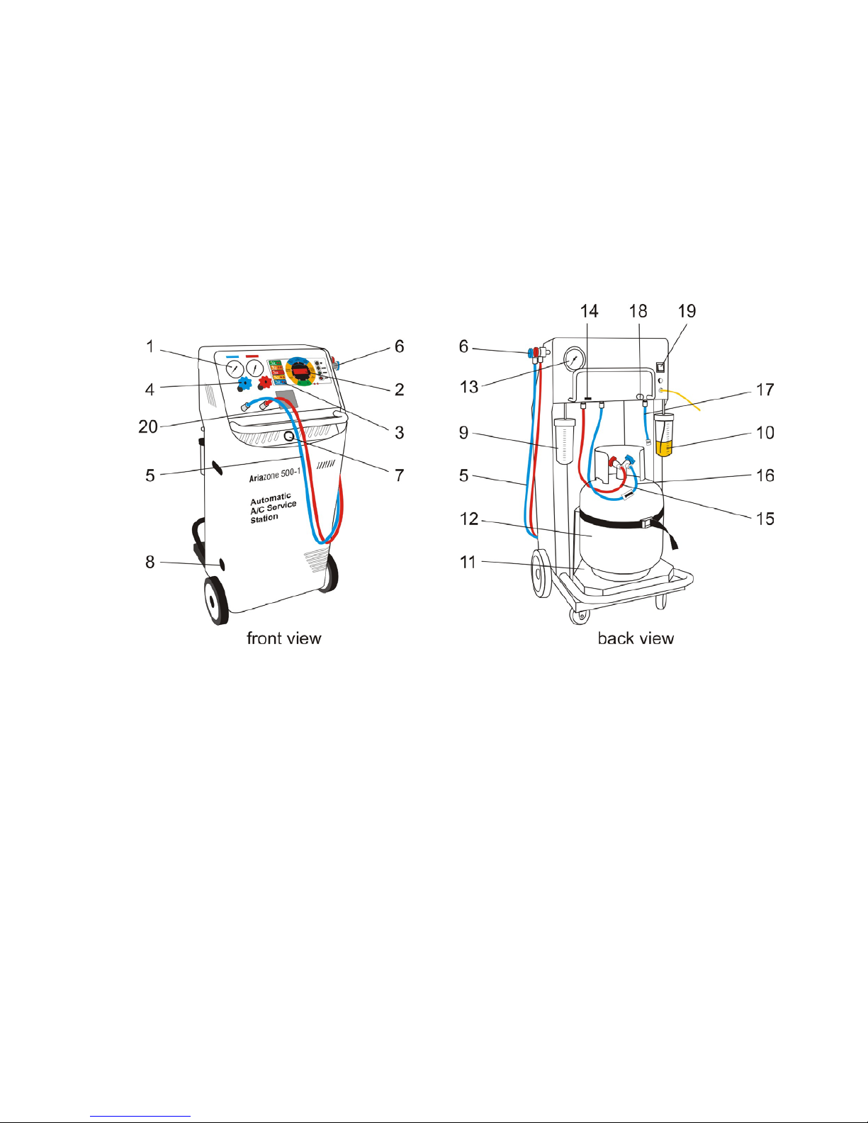
6. Service Hoses Quick Couplers
Service hose quick couplers allows the operator to connect the Ariazone system, to the vehicle
air-conditioning system service ports without the risk of exhausting refrigerant in to the
environment.
7. Moisture Indicator - The moisture indicator is conveniently mounted on the console for
added protection to indicate the condition of refrigerant and filter change intervals. The
following colours correspond to the following moisture content,
Green or Blue Dry, Yellow or Pink Wet,
8. Vacuum Pump oil level - oil level must be checked when the pump is running, the oil level
should be even with the line on the sight glass. Under filling will result in poor vacuum
performance. Over filling can result in oil exhausting from pump vent.
9. Recovered Oil Drain Reservoir - A vessel of 250ml (8.75oz) is mounted on the right
rear of the unit to electronically gauge the amount of oil recovered from the air-conditioning
system, if any.
10. Oil Storage Reservoir - A vessel of 250ml (8.75oz) is mounted on the left rear of
the unit to electronically inject the oil back in to air conditioning system, or to select the
desired amount of oil to be injected.
11. Cylinder platform / Electronic scale – To electronically display amount of refrigerant in
storage cylinder, being recovered or charged in to air-conditioning system.
12. Refrigerant Cylinder 12 or 25kg is used to store the recovered and purified refrigerant.
13. Cylinder Non-condensable Indicator - A large pressure gauge is mounted on the back
upper side of Ariazone unit to indicate to the technician of any non-condensable (air) built up
in the storage cylinder.
14. PC communication port (if fitted)
15. Cylinder vapour hose
16. Cylinder liquid hose with ball valve
17. Adapter hose
18. Vacuum port - To attach micron gauge when required
19. Power switch
20. Printer

8
6. Preparing the machine for use
Perform the following steps to prepare the Ariazone System for use.
1. Remove the unit packaging.
2. Check to ensure that all of the accessory components are present:
- Cylinder (12) (if ordered)
-Adapter hose (17)
-Cylinder hoses (15) and (16)
-Service hoses (5)
-User's manual
-Cylinder strap
3. Place the cylinder (12) on the Ariazone platform (11) and secure it with the strap provided.
4. Check the vacuum pump oil level (8). The oil level should be slightly above the line on the
sight glass when the pump is not running.
5. Power up (19) the unit. The unit will perform a lamp test, whereby all led displays are

9
illuminated. This will enable the operator to determine if any displays have failed. After the
sequence has been completed, the display (2) will indicate the number of hours left before
equipment servicing is required followed by the amount of refrigerant in the storage cylinder
(12).
6. Mode Selection. To select a mode of operation, press either the 'UP or 'DOWN' arrow keys
until the enunciator (3) is beside the desired function. Press 'START' which will cause the
Ariazone unit to enter the selected mode.
Any mode that has been selected can be exited by pressing the 'STOP' key.
Note that if a valid key was depressed, the Ariazone unit will beep.
If an inappropriate selection has been made, i.e. attempting to select a mode whilst another
mode is in operation, the Ariazone unit will ignore the key pressed and not beep.
7. Evacuate refrigerant cylinder.
Please perform following steps to Evacuate refrigerant cylinder (12): before filling with
refrigerant:
- Connect Ariazone service hose (5) to cylinder (12) with adaptor (17).
- Open cylinder (12) valve, service hose (5) quick coupling and handle (4) on the command
panel.
- Press the 'UP" arrow key to select Evacuation function. Press, "START" and with the
keys "UP" and "DOWN" select 30 minutes. Press "START" key again and the unit will
start the evacuation process.
Note, Ariazone recommends that a 25kg refrigerant cylinder be evacuated for a
minimum time of 30 minutes.
- After 30 min. the unit will automatically stop. After closing the cylinder valve, disconnect the
service hose (5) and adapter (17) from cylinder and place to the storage ports.
8. Place refrigerant cylinder on Ariazone platform and secure with strap provided. Connect
cylinder hoses. Liquid hose (16) to the liquid side on the cylinder and vapour hose (15) to the
vapour side.

10
9. Open both cylinder valves and open liquid hose (16) ball valve.
The Ariazone 5001FA is now ready for use.
7. Printer
The printer is equipped with two keys and green led:
>> Paper feed
II on line / off line
The green led shows the state of the printer:
Led constantly on - Printer in line
Led blinking - Printer not in line or no paper
Led off - Press II. If the problem persists, contact Ariazone International or authorized distributor.
Paper width: 57-58mm
Max paper thickness: 80 µ
Use only Ariazone paper in accordance to specifications.
Printing report:
After completion of every operation the unit will print a report as follows.

11

12

13
8. Filling cylinder with refrigerant
Unit cylinder (12) may be filled with refrigerant by following procedures.
a. Using disposable cylinder
Connect the suction (blue) service hose (5) to a storage cylinder liquid valve by using the adapter
hose (17). Open liquid valve on the storage cylinder, open service hose quick coupling (5) and
hand manifold blue valve (4) .
With "UP & DOWN" keys, select the recovery function. By pressing "START" key, select amount
of refrigerant to be transferred, with the UP and DOWN key. The Ariazone unit will automatically
transfer the selected amount of refrigerant from the storage cylinder to the Ariazone cylinder (12).
When the selected amount of refrigerant is transferred, close the storage cylinder valve and allow
the Ariazone to recover the refrigerant in the service hose (5). Once the function is completed the
Ariazone will display the symbol "done" and the amount of refrigerant transferred will be displayed
in kg or lb on main display (2).
b. Using refillable cylinder
Have cylinder sitting upright, connect the suction (blue) service hose (5) to storage cylinder liquid
valve by using the refrigerant transfer hose (17) supplied, open liquid valve on storage cylinder,
open service hose quick coupling (5) and console blue hand valve (4)
Important:
a. Always keep a minimum of 2 - 3 kg in the 5001 cylinder (12).
b. Do not allow the cylinder to be filled above 80% capacity.
c. Never transport an overfilled cylinder. Refrigerant expands when heated and
may cause the pressure relief valve to open and exhaust refrigerant in to the
atmosphere or the cylinder may rupture.

14
9. Connecting Ariazone 5001FA to the A/C system
Use the service hose (5) quick-connect couplers to connect the hoses to the A/C system service
ports, bearing in mind that BLUE must be connected to the low-pressure (suction) side and RED
to high pressure (discharge) side.
If the system is equipped with a single service port, connect only the relative hose.
Note: Before connecting the quick couplers, clean the a/c ports of any foreign material.
Winding the quick coupler hand wheel clockwise, will allow the refrigerant to flow through the
hoses. Turning hand wheel in opposite direction, the flow will be closed. If there is any refrigerant
in the air-conditioning system, the pressure gauges will indicate a pressure rise.
Important: Console manifold hand valves (4) need to stay closed, not to allow
refrigerant to enter the service equipment until the required function has been
selected.
Ariazone 5001 gauges (suction & discharge) are important and useful instruments, the operator
should have basic understanding between gauge reading and air-conditioning system operation,
in order to correctly diagnose any possible system malfunction.

15
10. Individual function selection procedure
With this procedure, all functions (refrigerant recovery & recycling, A/C system evacuation,
recovered oil drain, new oil and UV dye injection and refrigerant charge) can be performed
individually.
The values for the quantity of refrigerant recovered, quantity of the oil recovered, vacuum time,
quantity of oil injected and quantity of refrigerant charged into the a/c system are automatically
printed at the end of each single operation.
10.1. Recovery & Recycling Mode
The purpose of the Recovery & Recycling mode is to recover refrigerant from the air conditioning
system, which will condense, purify and store the liquid refrigerant in the storage cylinder ready
for re-use.
To initiate the Recovery mode, press the 'DOWN' key once, followed by 'START' on the console.
Display will show "- - - -". Now, there are two choices:
1. To recover all the refrigerant from a storage cylinder or A/C system, press “START” again.
2. To select quantity of refrigerant to be recovered or transferred from a storage cylinder or A/C
system, use the "UP" or "DOWN" keys to select the desired amount, and press "START”
Note: Open the hand manifold valves (4) on the console to allow the flow of the
refrigerant from the a/c system before making the above selection.
Also, open valves on the unit storage cylinder (12) and ball valve on the cylinder
liquid hose (16).
During the recovery process, the 'Recovery' mode enunciators will now be ON and the display (2)
will indicate the amount of refrigerant being recovered.
In normal operation the above condition will be maintained until a vacuum of -0.4 bar (15 In Hg) is
reached at either the discharge or suction ports. When this occurs, the machine will beep once,
and the Ariazone will enter the recovery "PAUSE" mode. In this mode, the Ariazone will shut
down the recovery function and pause for 3 min., which during this time the recovery mode
enunciator will be ON constantly. The display (2) will indicate "PAUSE". During this function, the
Ariazone is monitoring whether the air-conditioning system pressure is increasing, due to any
refrigerant that may be left in the accumulator or dryer. If the pressure increases above zero, the
machine will re-start the recovery function automatically recover the remaining refrigerant.

16
If at the end of Recovery process a sufficient vacuum has been maintained, the Ariazone will
stop, and the display (2) will indicate alternately 'DONE' and the amount of refrigerant recovered
will be displayed in (kg or lb) depending on the operator’s selection.
Press 'STOP' on the console, the unit will display "busy" for 5 seconds.
The values for the quantity of refrigerant recovered will be automatically printed.
Recovered Oil Drain
After completion of recovery function, the unit will automatically drain the recovered oil (if any) into
recovered oil vessel (9) to electronically calculate amount of oil that has been recovered. The
value of the recovered oil will be automatically printed.
Conditions that will halt the recovery mode
The above sequence assumes that neither the stop button was pressed, or that no undesirable
condition occurred. The following conditions will cause the Ariazone unit to halt the recovery
function.
1. Refrigerant cylinder (12) full. To protect the storage cylinder from being overfilled, the unit will
not allow the operator to recover refrigerant once it has reached 80% of its capacity.
2. Air conditioning system empty. If the A/C system pressure is not above atmospheric
pressure, the recovery function will not be activated.
3. High Pressure. If the operating pressure of the Ariazone exceeds 26 bar (350 psi), the
Ariazone unit will stop and display 'H- PRES'. The following can cause the above:
•Cylinder (12) valves not open.
•Restricted cylinder hose (16). Check the ball valves.
•Excessive high ambient temperatures.
•Excessive air in refrigerant cylinder
•Faulty pressure control
•Recovery pump thermo control faulty.
In all the above circumstances, press the 'STOP' key to return to the machines initial mode.

17
10.2. Evacuation Mode
In the evacuation mode the air and moisture in the air conditioning system is removed and
exhausted to the atmosphere. The evacuation pump in the Ariazone system is capable of
developing a vacuum of -0.99 bar (29.99 in hg). The evacuation mode runs for a predetermined
time selected by the operator.
To initiate evacuation mode, press the 'DOWN' key twice, followed by the 'START' key. Select the
desired evacuation duration by pressing the 'UP' key to increase or ‘DOWN’ key to decrease time
duration. Once the desired time has been selected press the 'START' key and the function will
commence.
Note: During evacuation mode manifold hand valves (4) on the console must be
open.
The evacuation time can be set from one minute to eight hours.
At any time the evacuation time can be paused or cancelled by pressing the stop button once to
pause, or twice to cancel the function.
The Ariazone 5001 system has a unique function that if the evacuation function is selected and
there is residual refrigerant in the air conditioning system, greater then 0.6 bar or 9 psi, the unit
would detect this condition, whereby it will beep six times to warn the operator. After this warning
the unit will automatically recover the residual refrigerant once it has recovered the entire
refrigerant it will start the selected evacuation function automatically.
Leak testing: After the evacuation process is completed, close both hand valves on
console (4). By closing the valves the unit is "isolated" from the A/C system to allow for
monitoring of any possible vacuum leak, which may exist in the air- conditioning system.
This is achieved by monitoring the suction and discharge gauges or micron gauge
connected on the vacuum port (18).
After completion of evacuation function, the unit will automatically print the report.

18
10.3. Oil or UV dye Injection Mode
The purpose of this function is to batch a user-defined quantity of refrigerant oil or UV dye from
the oil reservoir (10) on the Ariazone 5001 to the vehicle air-conditioning system.
Important: The Ariazone 5001 requires that the air conditioning system has
previously been evacuated to a maximum vacuum before this function can be
carried out.
Open the discharge (Red) and suction (Blue) hand manifold valves (4) on the console. Make sure
you have sufficient oil in the oil reservoir (10).
Select the Oil Injection mode by pressing the ' UP or DOWN' keys, followed by the 'START' key.
Select the desired amount of refrigerant oil 'UP' key to increase or ‘DOWN’ key to decrease the
value. Once the desired amount has been selected press the 'START' key and the function will
commence.
After completion of oil injection, the unit will automatically print the report of the oil injected into
the A/C system.
Conditions that will prevent oil injection
The Ariazone will not inject oil if the following conditions exist:
-Insufficient vacuum.

19
-Hand manifold valves (4) not opened on console.
-Schrader valve on A/C system service port not depressed.
-No oil in the reservoir (10).
10.4. Refrigerant Charge Mode
The purpose of the refrigerant charge mode is to batch a user-defined weight amount of
refrigerant into the air-conditioning system.
Important: Ariazone recommends that the A/C system is always properly
evacuated for a minimum time of 30 min and vacuum leak tested, before refrigerant
is charged in to the A/C system. This process will help protect our environment
and the air-conditioning system.
To initiate charging mode, press the 'UP' key twice, followed by the 'START' key. Select the
desired refrigerant amount by pressing the 'UP' key to increase or ‘DOWN’ key to decrease. The
smallest increment of refrigerant charge weight is 0.02 kg. If the units of weight are to lb the
smallest increment of refrigerant charge weight is 0.02lb. The maximum refrigerant weight that
can be set at this point is determined by the actual refrigerant weight available in the cylinder (12).
Holding the 'UP' or 'DOWN' keys for longer than two second will cause the increments of weight
change to increase or decrease rapidly.
Once the refrigerant charge weight has been set, press the 'START' key and open appropriate
hand manifold valve depending on whether you are charging with the engine running or engine
stationary and if the A/C system is OFF or ON.
The display (2) will start from zero and will indicate the amount of refrigerant that has been
charged into the air-conditioning system. This function can be paused at any time, by pressing the
'STOP' key once, or twice, to cancel the function.
If the charge function has been paused, the amount of refrigerant that has been charged to that
point will be displayed, to continue the charge function press the 'START' key.
Once the present refrigerant weight has been charged, the charge function will automatically stop
and the display will indicate 'DONE'. The operator can return the machine to its initial state by
pressing 'STOP' key on the console.
After completion of refrigerant charge, the unit will automatically print the report of the amount of
refrigerant charged into the A/C system.

20
Conditions that will prevent refrigerant charging
-If there is little or no refrigerant in cylinder (12). The operator will not be able to
select the desired amount of refrigerant required.
-If the cylinder (12) valve is closed.
-If the hand manifold valve (4) is closed.
-If the A/C system service port Schrader valve is not depressed.
11. Automatic Cycle Procedure
In the Automatic cycle mode, all the operations (refrigerant recovering and recycling, recovered
oil discharge, evacuation, new oil injection and refrigerant charging) are performed automatically,
in one cycle.
Quantity of the refrigerant recovered, recovered oil, vacuum time, new oil injected and refrigerant
charged into the A/C system are printed at the end of each single operation.
Fig1, to initiate the Automatic cycle mode, press the 'UP' key once, followed by 'START' on the
console. Display will show "- - - -" and recovery weight led will flash. Press "START" button to
confirm the recovery function.
Fig1.
Fig2, is flashing vacuum time led. Select the desired evacuation duration by pressing the 'UP' key
to increase or 'DOWN' key to decrease time duration. Once the desired time has been selected
press the 'START' key.
Fig 2.
Fig3, oil injection enunciator is flashing. Operator can choose automatic oil injection by pressing
"START" button or to select the different amount of refrigerant oil by 'UP' key to increase or
'DOWN' key to decrease the value. Once the desired amount has been selected press the
'START' key.
Other manuals for 5001
2
Table of contents
Popular Air Conditioner manuals by other brands

Hitachi
Hitachi RAS-E24CAK installation manual

Hitachi
Hitachi RPC-2.0FSR Installation & maintenance manual

Geostar
Geostar ASTON SERIES installation manual

Sharp
Sharp AH-AP9SMD Operation manual

Mitsubishi Electric
Mitsubishi Electric Mr.Slim SEZ-KD25VAQ installation manual

Bergstrom
Bergstrom Bycool Compact 1.4 User handbook