Table of Contents
INTRODUCTION
................................
................................
................................
.........................
2
Purpose of This Guide
................................
................................
................................
2
The Device
................................
................................
................................
.........................
2
................................
................................
................................
................................
................................
................................
Device Features
................................
................................
................................
3
Specifications
................................
................................
................................
3
Safety Precautions
................................
................................
................................
4
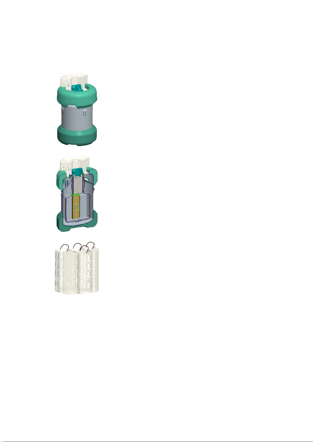
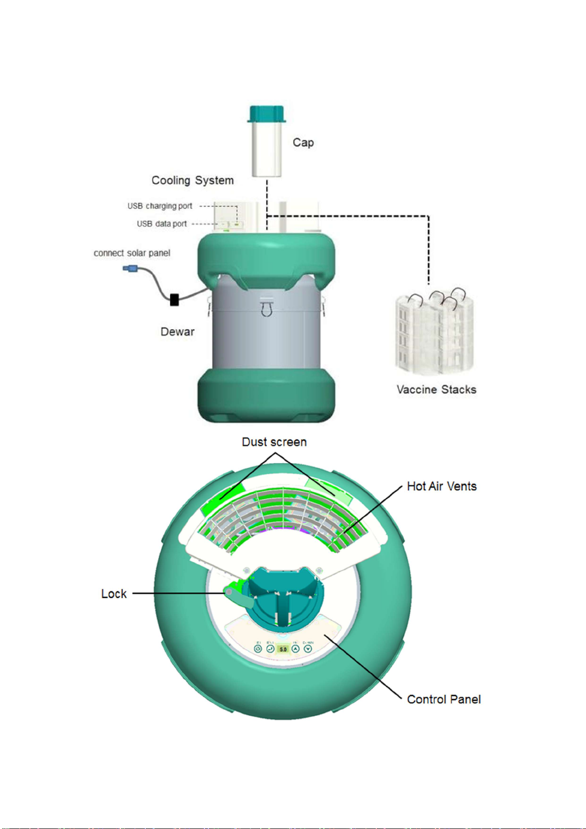
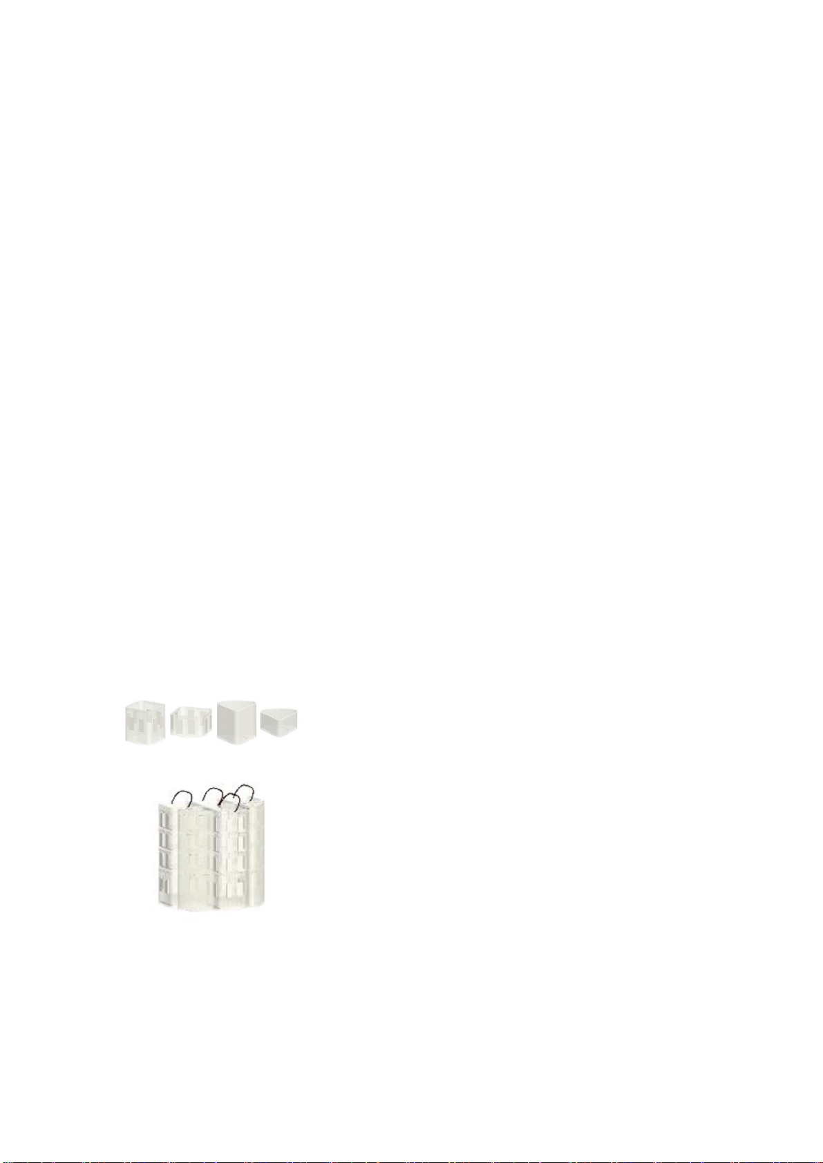
PARTS OVERVIEW
................................
................................
................................
5
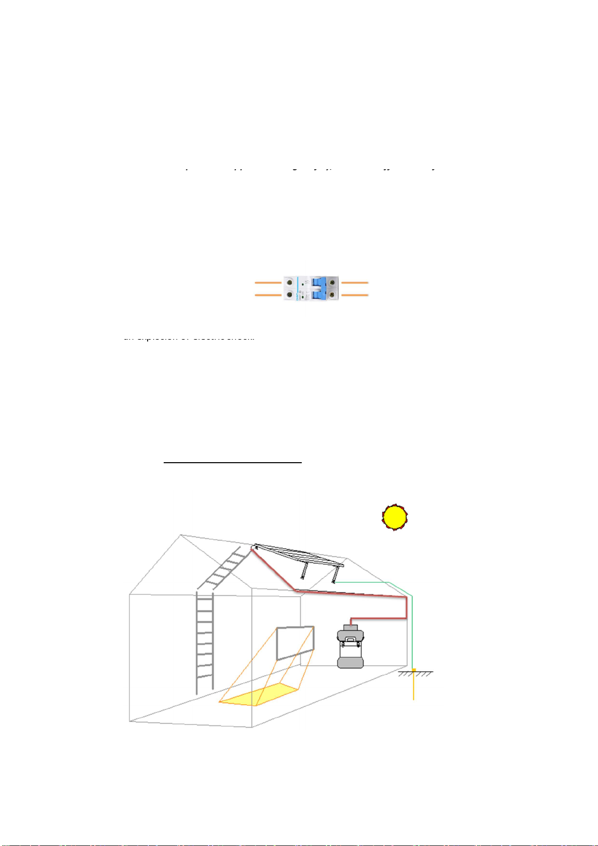
INSTALLATION
................................
................................
................................
...........................
6
Preparation
................................
................................
................................
6
Positioning the Device
................................
................................
................................
6
USE OF THE YBC
10
................................
................................
................................
7
................................
................................
................................
.........................
................................
................................
................................
.........................
Daily Use
................................
................................
................................
...........................
7
Electronic System
................................
................................
................................
11
MOVE AND TRANSPORT INSTRUCTIONS
................................
................................
14
CLEANING AND STORAGE
................................
................................
................................
15
Cleaning
................................
................................
................................
..........................
15
Condensate
................................
................................
................................
16
TROUBLESHOOTING
................................
................................
................................
17
DISPOSAL AND RECYCLE CONSIDERATION
................................
................................
18
................................
................................
................................
............................
WARRANTY
................................
................................
................................
............................
19
1