Thank
you
for
choosing
the
Artison
Portrait
Home
Theater
System.
We
are pleased
that
you have selected
our
high-performance
audio
products.
INTRODUGION
The Portrait Home Theater System is the only true 5.1/7.1 Channel solution available
on
the
market today that
is
specifically designed for use with flat panel displays and which is fully
compatible with rear projection displays,
as
well.
The Portrait System is the high performance choice for state-of-the-art
DVD,
DTS,
SACD,
and
DVDA multi-channel audio formats. The system faithfully reproduces music and movie sound
tracks without compromise, and does not visually detract from the contemporary appearance
of
your flat panel or rear projection display.
To
accomplish this, new technologies
had
to
be
refined and integrated into the system.
The
Portraits provide alifelike widening
of
the front sound
stage,
and eliminate the
need
for aseparate
center channel
box
above
or below the
screen.
These technologies include
the
development
of
new types
of
small but powerful woofers and tweeters
to
provide high-definition, high-impact
surround sound.
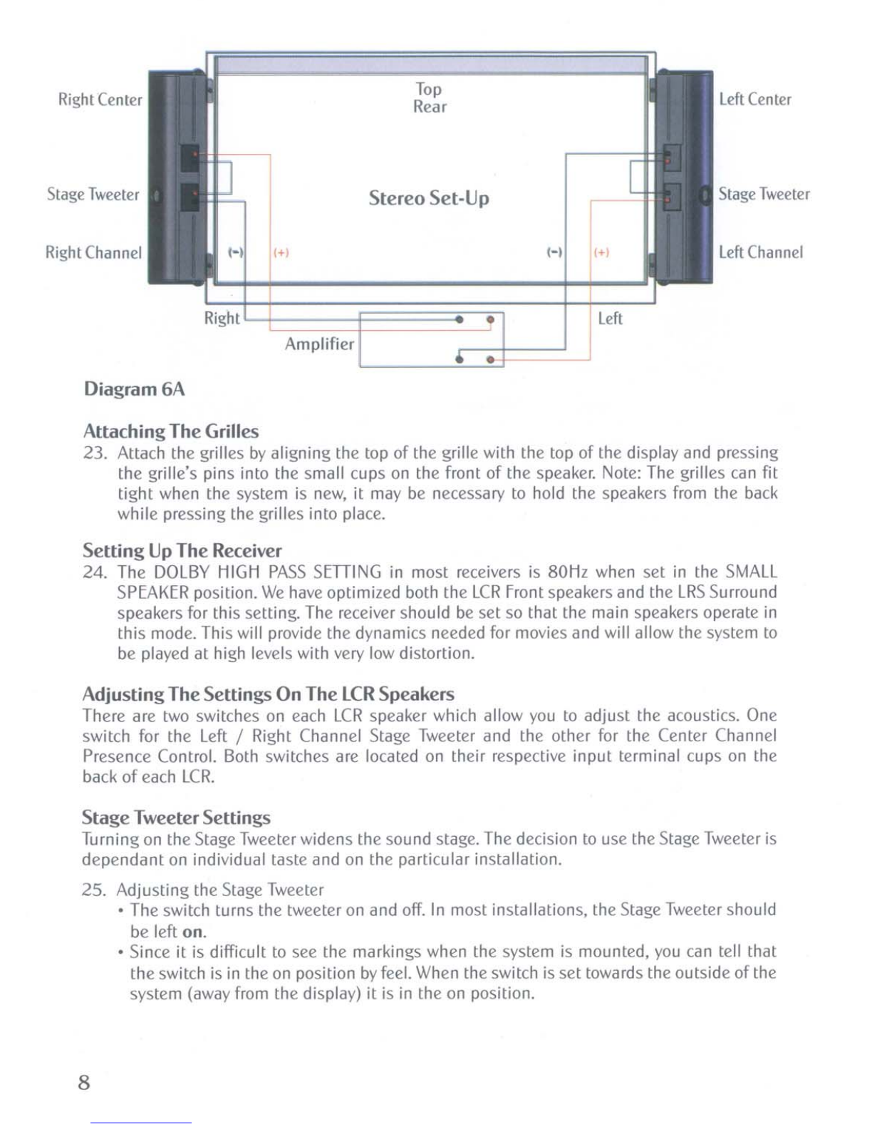
The Portrait System is designed to
be
powered
by
any high quality
AV
receiver or
decoder/amplifier combination. The hookup is exactly the same
as
atypical
5.1
or
7.1
Channel
systems with one important difference -the
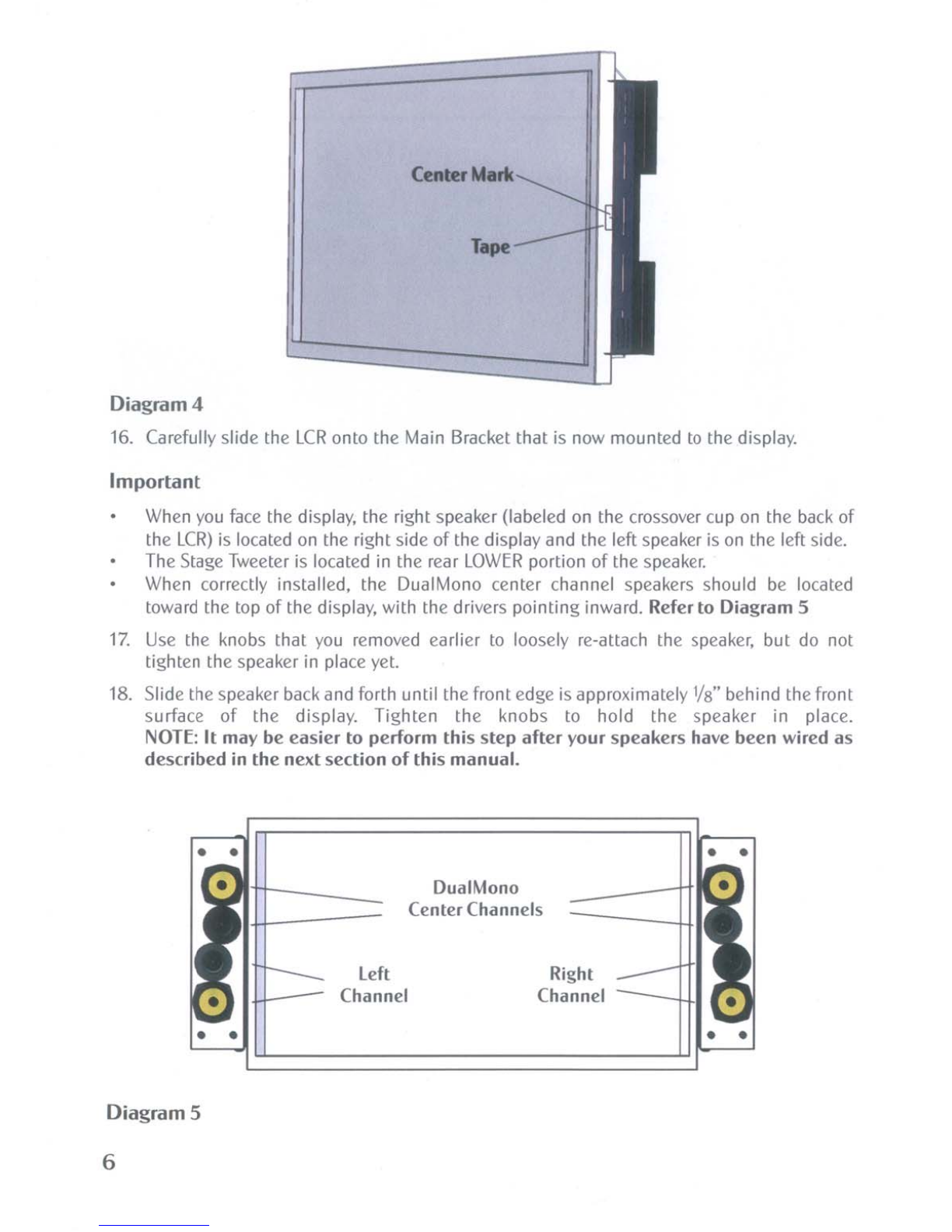
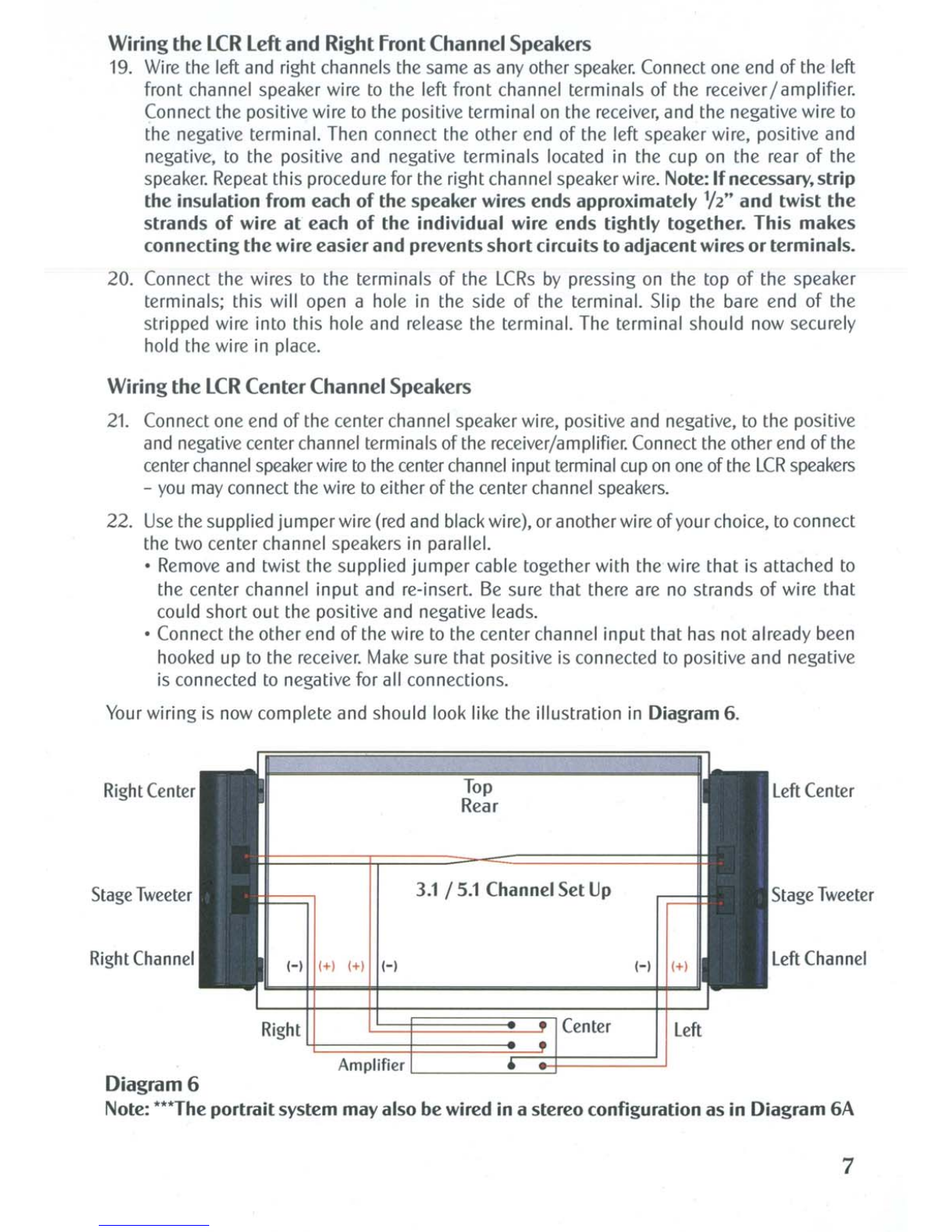
LCR
Front Channels include aunique DualMono
Center Channel speaker in the upper
half
of
each
of
the
LCR's
Left and Right speakers.
The
Center Channel wire from the receiver is hooked up
to
one
of
the two Center Channels
and
then
it
is connected (using the included hookup jumperwire)
in
parallel with the other Center
Channel. Together, the DualMono Center speakers deliver accurate center channel sound that
appears
to
come directly from the center
of
the display screen.
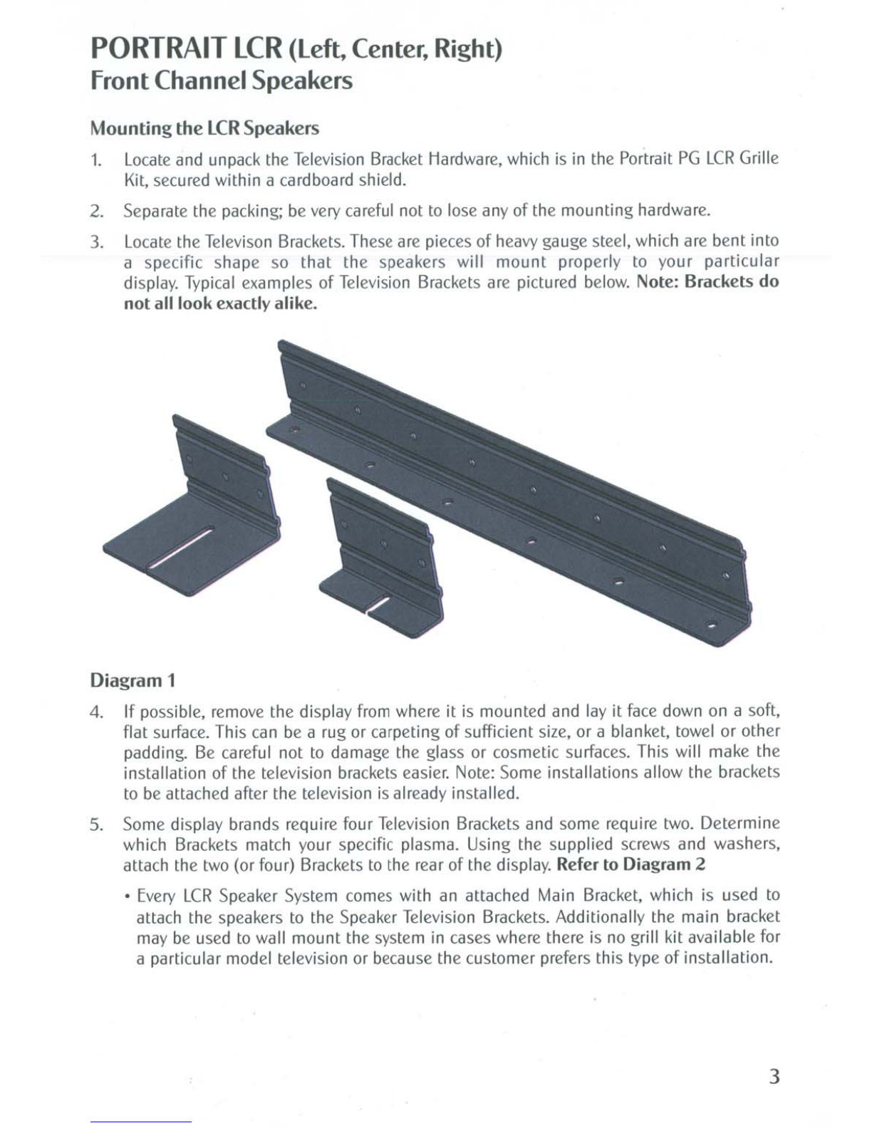
The
LCR
speakers
are
designed to attach directly
to
aflat panel display, whether the display is
placed on astand or mounted to the wall. Included
in
each
LCR
Grille and Bracket Kit
are
grilles that match the height and color
of
the plasma or
LCD
display and Television Brackets
that allow the speakers to
be
attached.
Portrait
Tower
Stands are available that allow placement
of
the
LCR
speakers next to the sides
of
modern rear projection displays. These stands preserve the acoustic advantages
of
the
Portrait System without physically altering the display's enclosure. Contact your Artison
Retailer for more information.
The following information will guide
you
through the installation
of
your Artison Portrait Home
Theater System.
If
you
need
assistance during this process, please contact
us
during normal
business hours, Pacific Time, at (775) 833-4344.
2