X-3D-BL User’s Manual
1 Introduction
Congratulations! You have just bought a powerful
high-end model aircraft kit!
Please read this manual thoroughly until the end befo-
re you start assembling your X-3D-BL and stick with
the proposed chronological order. Warranty is void if
this manual is not strictly followed.
WARNING!
Assembling the X-3D-BL requires some experience
with building R/C models and soldering. If you do
not feel like you could do this on your own, please
make sure you get some help from a person with the
experience required. If cables are connected falsely
hardware can be destroyed. WARNING! Such cases
are not covered by warranty!
A motorized model aircraft is not a toy! It should only
be flown by adults. Improper assembly or operating
can lead to severe injuries and / or damages. Trouble
with your remote control due to interferences can
occur any time without prior notice. Sometimes, a
model aircraft can suddenly become uncontrolla-
ble due to a failure of any component, including
mechanical parts and electronics. In this case, the
model can rapidly move towards any direction. Make
sure you always keep a safe distance to people,
animals, obstacles or things of any kind, traffic roads,
etc.. There are country-specific laws regulating the
operation of model aircrafts that definitely have to
be obeyed. Furthermore, we strongly recommend to
effect a liability insurance for model aircrafts. The
manufacturer and your dealer of the X-3D-BL do
not have any influence on, nor can they monitor the
correct assembly and proper operation of your model
aircraft. Always be aware of the dangers mentioned
above and act accordingly. There is no liability of the
manufacturer nor the retailer at all, as far as legally
approved.
Our products are hobby-products and solely meant for
usage in non-commercial ways. It is not allowed to
use them for any commercial or military purposes.
Using any of our components for larger scale flying
objects is explicitly forbidden.
SUBJECT TO CHANGE WITHOUT NOTICE.
1.1 System overview
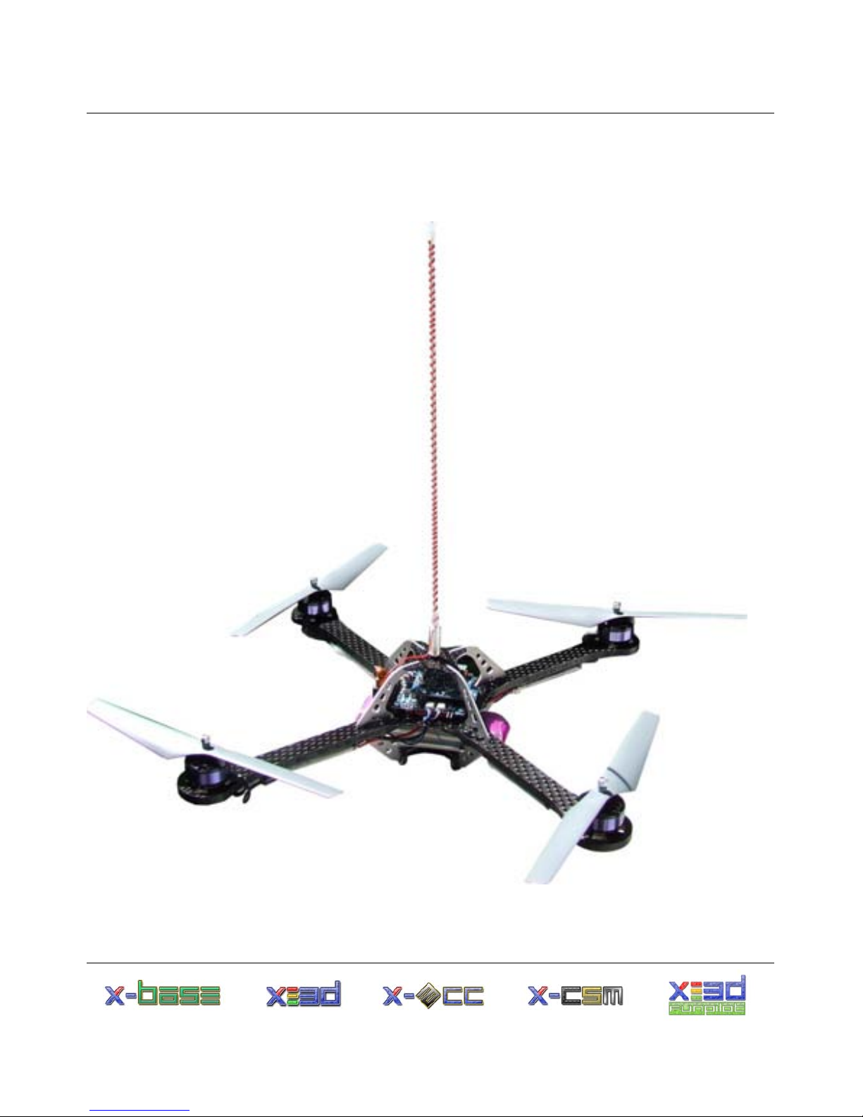
1.1.1 X-CSM
The X-CSM is the mechanical frame of the X-3D-
BL UFO. The booms, which are made of a rigid
carbon fiber-balsa wood sandwich material, can be
replaced individually. The central unit of the frame
called the ”X-CSM Core” is made of light weight
laser-cut magnesium parts. Being built out of these
state-of-the-art materials the X-CSM is a very robust
high-tech basis for your quadrotor aircraft.
www.x3d-shop.de - 4 - www.asctec.de