Asoni CAM736MIR User manual

2 Megapixels
Dome Network Camera
CAM736MIR/CAM736MIR-PoE
User’s Manual

1
Table of Contents
1Overview ....................................................................................................................................................................... 2
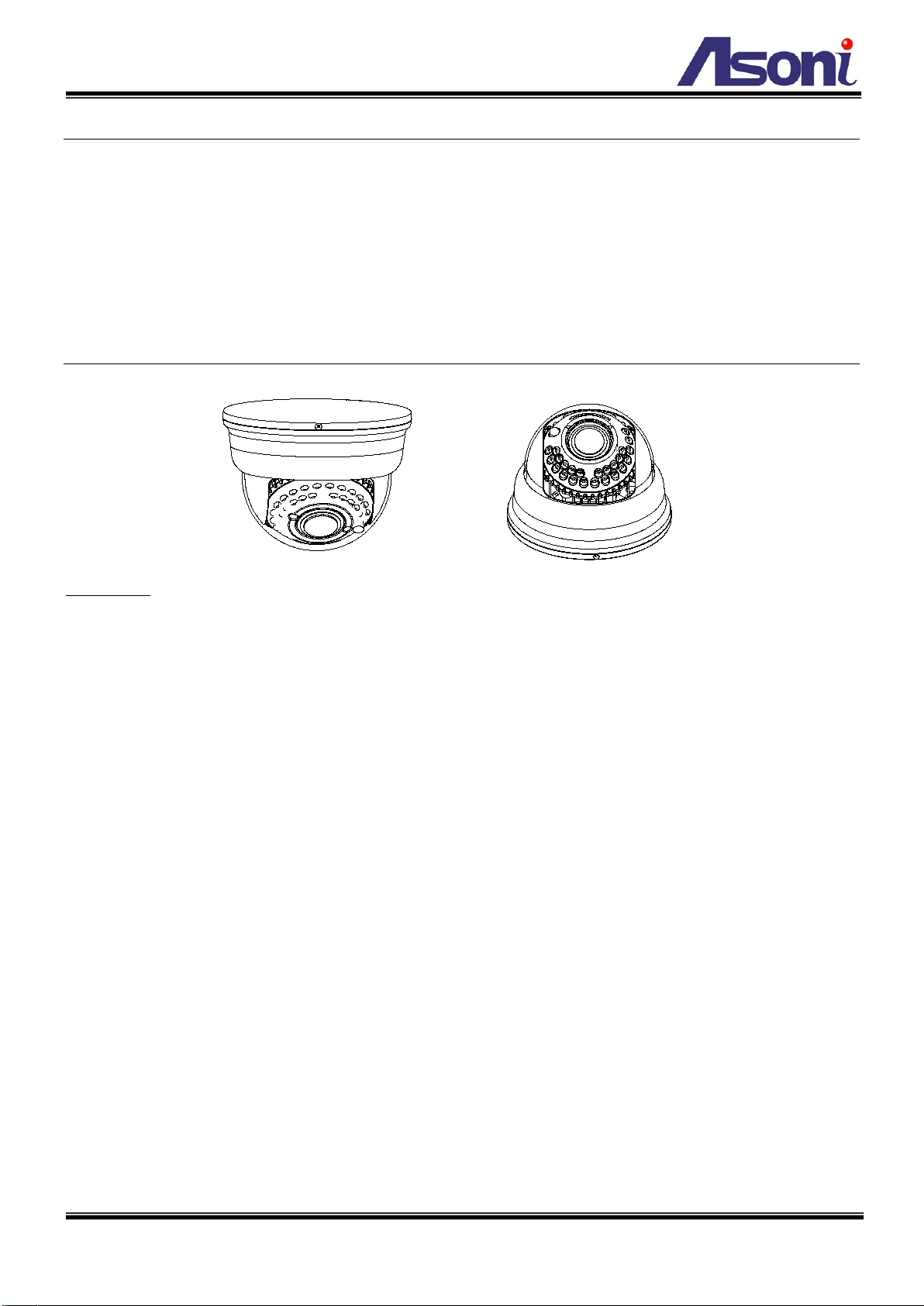
2Product Description .......................................................................................................................................................2
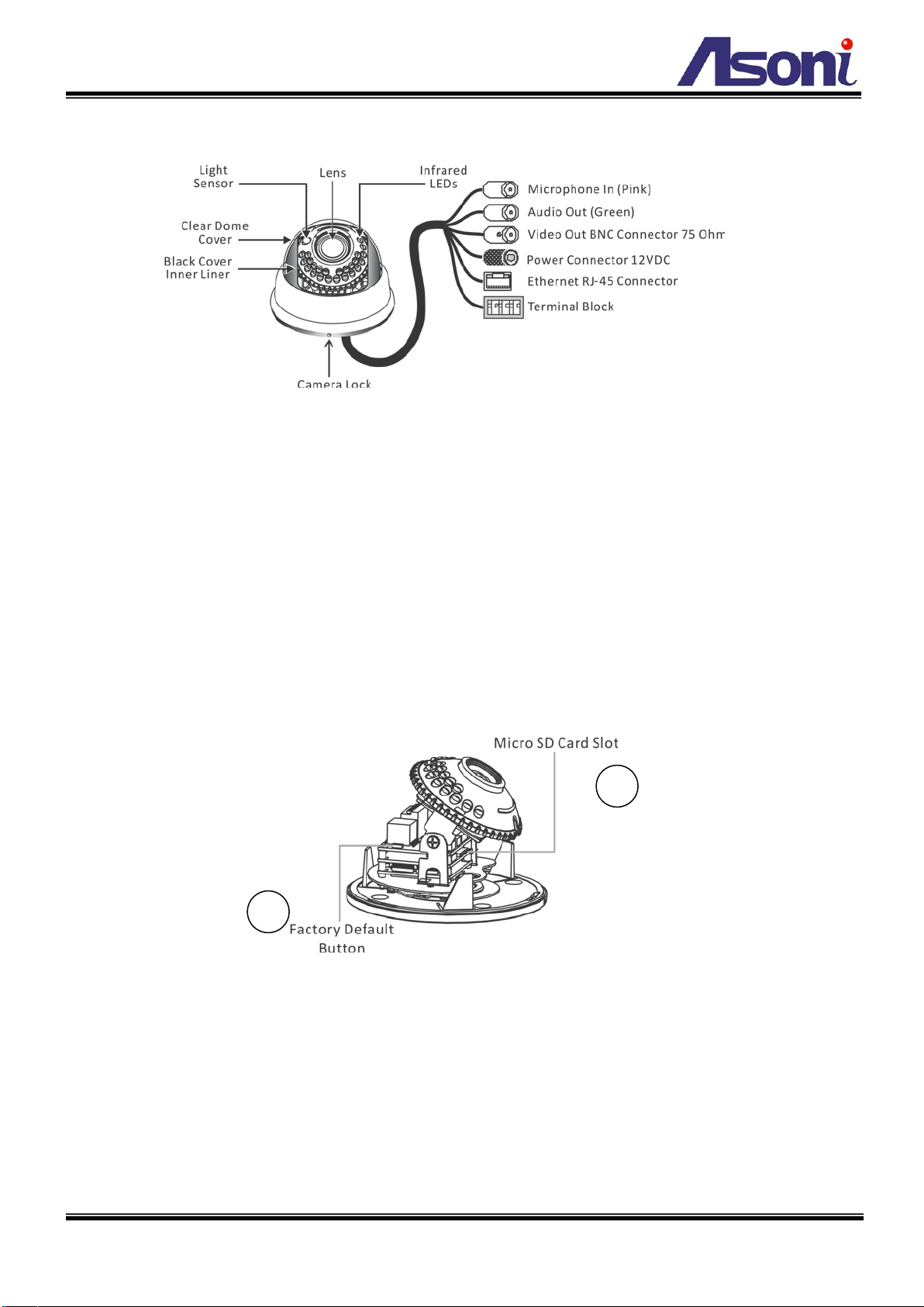
2.1 Hardware Description.............................................................................................................................................3
3Setting up the Network Camera.....................................................................................................................................4
3.1 Read Before Use .....................................................................................................................................................4
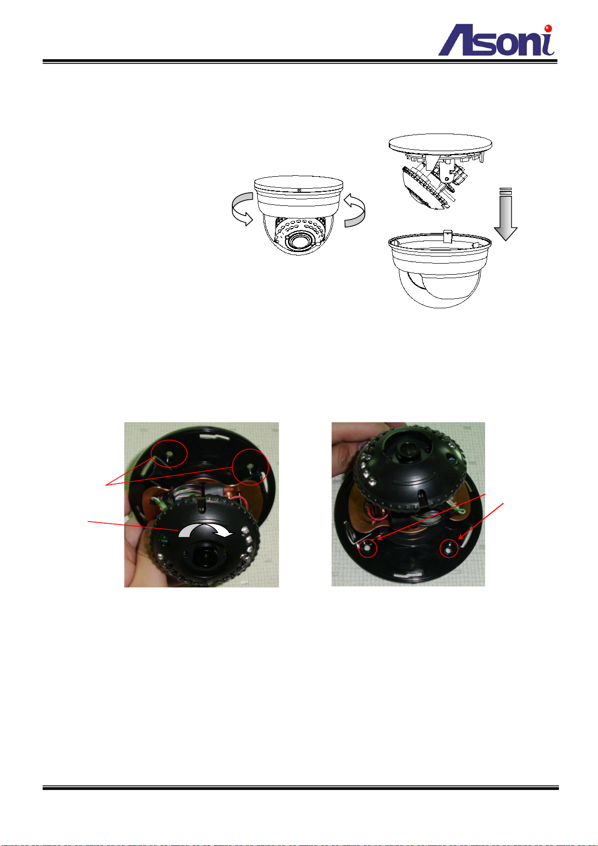
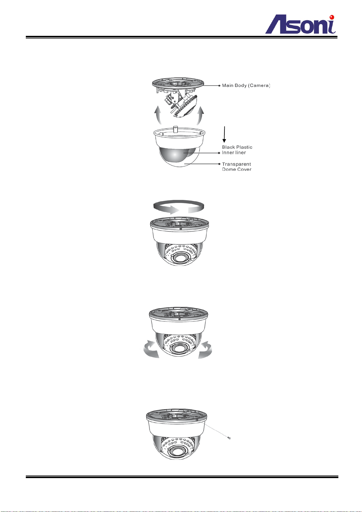
3.2 Hardware Installation Steps ...................................................................................................................................4
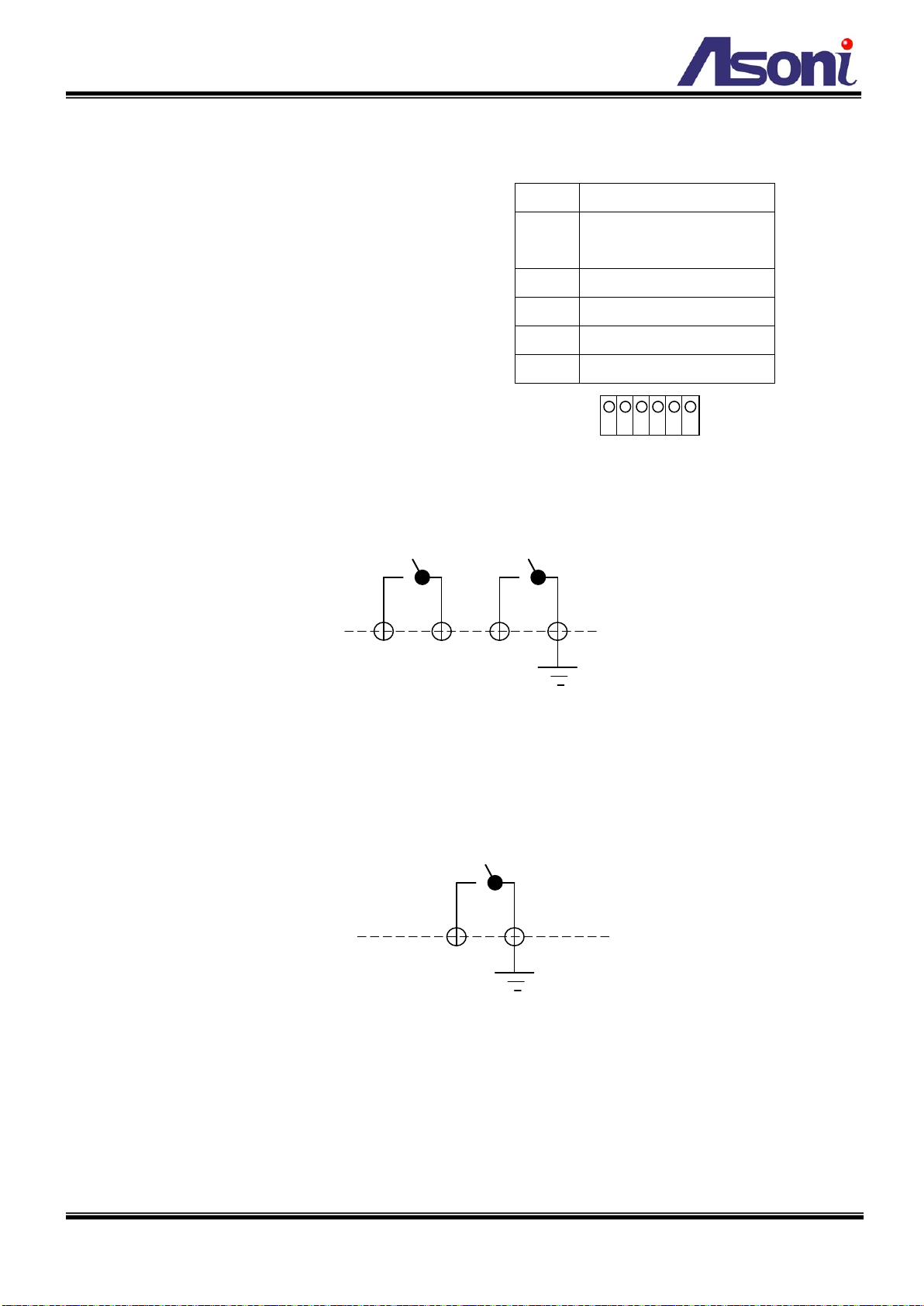
3.3 Using the Terminal Block ........................................................................................................................................8
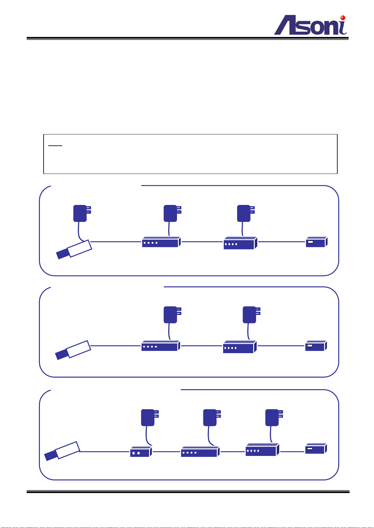
3.4 Network Connection for PoE/Non-PoE Cameras ...................................................................................................9
3.5 Using the Micro SD Card.......................................................................................................................................10
3.6 Using the Network Camera for the first time .......................................................................................................11
4Accessing the Network Camera ................................................................................................................................... 12
4.1 Find Camera..........................................................................................................................................................12
4.2 Before Assigning an IP Address ............................................................................................................................12
4.3 Assigning the IP address to the network camera .................................................................................................13
4.4 Access the camera from the browser...................................................................................................................14
4.5 The Live View Page ...............................................................................................................................................16
4.6 iPhone Camera Viewer .........................................................................................................................................17
5Configuring the camera................................................................................................................................................ 19
5.1 Video Settings.......................................................................................................................................................19
5.2 Camera Settings....................................................................................................................................................23
5.3 Storage Settings....................................................................................................................................................27
5.4 Event Settings.......................................................................................................................................................29
5.5 Network Settings ..................................................................................................................................................38
5.6 System Settings ....................................................................................................................................................44
6Troubleshooting .......................................................................................................................................................... 48
6.1 Factory Default .....................................................................................................................................................48
6.2 Viewing the camera from a remote location .......................................................................................................48
7Frequently Asked Questions ........................................................................................................................................ 52

2
1Overview
The camera series is a high-end 2 Mega Pixel Dome Network Camera, which is designed for professional security
applications. This network camera is equipped with ICR (IR-Cut filter Removable) and Infrared LEDs, and provides
outstanding day and night performance. It comes with a 2 Mega Pixel CMOS Sensor, with a maximum resolution of
1600 x 1200, delivering sharp image quality. Furthermore, the DPTZ (Digital Pan Tilt Zoom) function allows user to
navigate any area of the monitored image with maintained sharp resolution. With unique features, this network
camera provides an ideal solution for surveillance and monitoring.
2Product Description
Key features
H.264 High Profile / MJPEG Dual Compression:
Offers the user the option to select H.264 or MJPEG compression.
ONVIF ® Compliant for Easy Integration & Fast Deployment:
Web services built-in with international standard protocols, integration cycles have been reduced and
deployment has become easier. ( Contact your distributor for documentation).
Multiple video profiles simultaneously for streaming:
Streams up to 8 independent streams with multiple profiles.
Different configurations can be set according to the bandwidth that is available from the network.
Infrared LED for Day & Night Model, 20 Meters
There are 24 infrared LEDs located underneath the transparent cover.
Audio In & Audio Out Connectors for Camera Audio enhancements
Offers an Audio In connector and an Audio Out connector to connect to an external microphone and
speaker, in order to transmit two way audio together with the video streaming.
Micro SD Card Slot for Local Storage
For saving snapshots that can be later checked by the user, upon events occurred during motion detection.
Analog Video BNC Out for Video Redundancy on Analog devices
The Network Camera has a video output with analog signal that allows connecting to analog monitors.
Alarm In & Alarm Out for connecting Alarm Devices
The Network Camera comes with a Terminal Block for connecting alarms to execute actions upon it.
Power-over-Ethernet IEEE 802.3 af for simplified connection ( Optional)
Make installations simple with connecting only one cable without additional powering sources.

3
2.1 Hardware Description
Video out BNC Connector (75 Ohm) for connecting analog monitor
Power Jack 12VDC for connecting AC/DC power adapter
Ethernet RJ45 Port for network connection
Terminal Block (6 pins) for Digital In/Out and load default activation
Microphone In (Pink) for connecting a microphone
Audio Out (Green) for connecting a speaker
Delete the clear dome cover in order to reach the following connectors:
1. Micro SD Card Slot
2. Factory Default Button
1
2

4
3Setting up the Network Camera
3.1 Read Before Use
The use of surveillance devices may be prohibited by law in your country. The Network Camera is not only a
high-performance web-ready camera but can also be part of a flexible surveillance system. It is the user’s
responsibility to ensure that the operation of such devices is legal before installing this unit for its intended use.
It is important to first verify that all contents received are complete. Take note of the warnings in the Quick
Installation Guide before the Network Camera is installed; then carefully read and follow the instructions in the
Installation chapter to avoid damage due to faulty assembly and installation. This also ensures the product is used
properly as intended. It is designed for various applications including video sharing, general security/surveillance,
etc.
3.2 Hardware Installation Steps
After unpacking the package and identifying its parts, assemble the network camera to run the device for the first
time.
It is recommended set up the camera before installing it to the intended location.
The following instructions will consist of basic steps that will help you through the hardware preparation.
Other required devices before powering up the Network Camera:
1. Personal Computer or Laptop; and
2. Network Hub or Switch and 2 (two) pieces of Ethernet Cable; or
3. 1(one) piece of Crossover Ethernet Cable
STEPS:
1. Use an Ethernet cable to establish connection between the camera’s network port and a network
hub/switch. Then, connect the power adapter (For Network Cameras that are
Power-over-Ethernet supported, the Power Adapter is not necessary). Refer to the images below.
2. After the Power Connector is plugged in, the Network Camera will boot up.
3. Wait a few seconds for the Network Camera to startup
4. Refer to the section of “Using the Network Camera for the first time” in the next page
Another end of the cable
to a network hub/switch
Another end of the power
adapter to a power outlet

5
Removing the clear dome cover
Delete the clear dome cover from the main body by gently turning the cover counter-clockwise to unlock and pull
free from the main body.
Mount the Camera on Wall/Ceiling
After the cover is removed, the camera can be mounted on a ceiling or a wall. When mounting the camera,
remember the conduit facing downwards (from the direction of the camera).
Delete the clear dome cover to locate:
1) Micro SD Card Slot
2) Terminal Block
3) Factory Default
Apply retention
screws and then
rotate the camera
module
Before mounting, remember to drill the holes on wall/ceiling for the screw holes and the conduit at the
bottom of the camera
Apply two other
retention screws

6
Pan/Tilt the Network Camera
The Network Camera is a 2-Axis dome network camera, for which you can adjust the camera to any direction by
using Pan base rotation, Tilt up / down mechanism.
How to adjust the lens focus
In order to adjust the focus of the Network Camera, turn the focus ring in
clockwise direction to get the appropriate image.
Note:it is required get connected to the Network Camera prior to adjust
the focus. The unit out from factory may already be focused. Unless
necessary, there might not be a need to adjust it.
Pan Base Rotation
Tilt Up/Down

7
Attaching the dome cover
After all necessary adjustment has been made reinstall the dome cover to the main body.
Reinstall the dome cover and the main body by turning the dome clockwise until it locks in place.
The dome comes with a black plastic inner liner placed within the dome cover. Therefore, after replacing the
dome cover rotate the liner so that the cutout slot (hole for viewing) is in the correct position and not blocking
the camera lens.
Camera Protection
To prevent unpredictable damage and burglary, lock-up the dome by using the countersunk head screw.
The black plastic inner
liner has a cutout slot for
viewing.

8
3.3 Using the Terminal Block
The network camera comes with a Terminal Block
that can offer multiple functions to the user:
Pin 1 ~ 4: Intended for triggering and receiving alarms
for the Event Configuration feature.
Pin 5, 6: Terminal block also provides 2 pins, Pin 5 and
6, for “load default”. With 2 wires connected to Pin 5
& 6, keep 2 wires in touch until System LED fast
flashing. Then, separate them to activate “load
default”.
Connecting Alarm devices
Connect Pin 1 and Pin 2 for an external relay device such as an alarm that expects to be activated.
Connect Pin 3 and Pin 4 for an external Triggering device for sending a signal into the Network Camera.
Refer to Chapter 5) Configuring the camera, Event Settings for more references on how to use the even trigger
and alarm to perform tasks such as taking snapshots and uploading images.
Load default
With 2 wires connected to Pin 5 & 6, keep 2 wires in touch (or close circuit) until System LED fast flashing. Then,
separate (or open) them to activate “load default”.
Pin 6
Pin 5
Pin 1 COM (Relay Common)
Pin 2 D-OUT (Relay Normal
Open/Close)
Pin 3 D-IN (Digital Input)
Pin 4 GND (Ground)
Pin 5 GND (Ground)
Pin 6 DEFAULT (Load Default)
Terminal Block Definition
1 2 3 4 5 6
Pin 1
Pin 2
Pin 3
Pin 4

9
3.4 Network Connection for PoE/Non-PoE Cameras
The Network Camera comes as an optional model which supports Power-over-Ethernet (PoE).
Using Power-over-Ethernet as power supplying mode, takes advantage of having a simple connection, with only
one Ethernet Cable to act like Data and Power transmission. And it is not necessary to use any Power Adapter
since the powering will be done directly through the Ethernet Connector.
Below a comparison between a Regular Ethernet connection and a connection using Network Camera with
built-in Power-over-Ethernet.
Note:For safety precautions, when using a PoE Video Encoder, ensure that the standard Power
Connector has been removed before plugging the Ethernet cable (which is attached on the other end to a
PoE Hub / Switch).
Power Adapter
Power Adapter
ADSL Modem
Network Camera with
Power-over-Ethernet
Broadband Router
POE
Switch
Ethernet cable Ethernet cable Ethernet cable
POE Switch & POE Network Camera
Power Adapter
Power Adapter
Power Adapter
ADSL Modem
Network Camera
Broadband Router
Hub / Switch
Ethernet cable Ethernet cable Ethernet cable
Non-POE Connection
Power Adapter
Power Adapter
Power Adapter
ADSL Modem
Network Camera with
Power-over-Ethernet
Broadband Router
Hub / Switch
Ethernet
cable Ethernet
cable Ethernet
cable
POE Single Injector & POE Network Camera
POE Injector
Ethernet
cable

10
3.5 Using the Micro SD Card
The network camera comes with a Micro SD card slot to allow users insert a Micro SD card to
save snapshots and videos into it. Refer to Chapter 5) Configuring the camera, Storage
Settings and Event Settings.
Before plugging / unplugging Micro SD card into / from the slot, it’s recommended to turn the
device off.
Note: The device does not support Hot-Swapping function.
Note: this unit supports min 2GB and max 32GB Micro SD/SDHC card and Class 6 or higher for smooth operation.

11
3.6 Using the Network Camera for the first time
The Network Camera is a network device and its use should be straightforward for those who have basic
networking knowledge. Making the initial steps for setting up the network camera will be based on a simple
network connection.
Option 1
Connect the network camera to a HUB / Switch which is connected to a PC
Option 2
Connect the network camera directly to a PC with a crossover cable.
After the network camera has its activity lights on, use the PC for setting up the IP Address of the Network
camera. Refer to the section of “Accessing the Network Camera” at the next page for detailed instructions.
Hints: Possible Network Configurations in your network infrastructure
1. Configuration 1
Internet Access: ADSL or Cable Modem
IP address: One real IP or one dynamic IP
Connection Type: Only the Network Camera connects to the internet
For fixed real IP, set up the IP into the Network camera. For dynamic IP, start PPPoE.
2. Configuration 2
Internet Access: ADSL or Cable Modem
IP address: More than one real IP or one dynamic IP
Connection Type: The Network Camera and PC connect to the internet
Device needed: Switch Hub
For fixed real IP, set up the IP into the Network camera and PC. For dynamic IP, start
PPPoE.
3. Configuration 3
Internet Access: ADSL or Cable Modem
IP address: one real IP or one dynamic IP
Connection Type: The Network Camera and PC connect to the internet
Device needed: IP sharing such as Hub / Switch and a Router
Use virtual IP, set up port forwarding in IP sharing.
(Suggestion: Refer to your Network Administrator if necessary for more information)

12
4Accessing the Network Camera
Before getting access to the Network Camera from user’s PC, it’s necessary to properly configure its network
setting. This camera uses 192.168.1.200 as the default IP address. If you would like to assign a new static IP
address, please install “CAM7 Series Device Search” from the CD-ROM, and then use this program to do that.
4.1 Find Camera
1. Once installed on the PC, click on [Start Menu >> All Programs >> Asoni >> Search Tooling >> Asoni CAM7
Series Device Search] to open the software.
2. The software automatically (or by clicking on “Search” button) displays cameras on the network. Identify
your camera by its MAC Address that is shown on the label of the camera.
3. Click on “Web” button or double-click on the identified camera item on the list to launch live viewing (it is
assumed that the network cable you’ve connected to your camera has provided a set of useable IP
address/subnet mask/Gateway), or click on “Config” button to configuring IP information.
4.2 Before Assigning an IP Address
Before assigning an IP address, make sure the Network Camera is powered on and correctly connected to the
network.
Obtain a LAN IP address not yet used and its related configuration from your network administrator.
The following will be required:
1. IP Address
2. Subnet Mask
3. Gateway
MAC Address: Each Network Camera has a unique Ethernet address (MAC address) shown on the label of the
Network Camera.
Hints: When assigning an IP Address
User can find necessary IP information by checking the current IP information of user’s host PC via Windows
command “ipconfig”:
-Click on Windows screen: the Start Menu >> All Programs >> Accessories >> Command Prompt.
-Type “ipconfig” at the command prompt to show the current IP information of user’s host PC.

13
For example,
C:\ >ipconfig
Windows IP Configuration
Ethernet adapter Local Area Connections:
Connection-specific DNS Suffix . : king-tech.com
IP Address. . . . . . . . . . . . : 192.168.1.102
Subnet Mask . . . . . . . . . . . : 255.255.255.0
Default Gateway . . . . . . . . . : 192.168.1.254
C:\ >
Then, use other IP address 192.168.1.xxx (1-253, except IP address of host PC 192.168.1.102), the same subnet
mask 255.255.255.0 and default gateway 192.168.1.254 for the network camera.
4.3 Assigning the IP address to the network camera
Select a Network Camera and click on “Setup”. Then, start to configure network settings, such as the following
fields:
IP Address / Subnet Mask / Gateway / DNS
Click on “Update” to apply the changes only by using administrator’s privilege (default user/password =
admin/admin).
To open the main page of the network camera, select your camera and click on “Web”.
* Remember to input a different
value for the last digits of IP address
from the “ipconfig”, ranging from 1
to 255.
Make sure you enter the same
values for Subnet Mask and Default
Gateway shown on your “ipconfig”
screen.

14
4.4 Access the camera from the browser
Start the IE browser, type the IP address of the network camera in the address field:
http://<IP of camera>
If the “HTTP Port” has been changed from “80”, type the URL as:
http://<IP of camera>:<HTTP Port>
Once the Network Camera is accessed, the Network Camera will request a Username and Password. The default
Username and Password is “admin” and “admin”.
Note: If “anonymous login” (see 5.6.2) is enabled, the Live View page will be shown without restriction. Or please
enter “admin/admin (default account/password)” to pass the authentication.
When the Network Camera is accessed via Internet Explorer, it will ask you to install the ActiveX component.
Note: during the webpage loading, you may be asked to allow the installation of Active X elements. Please allow
it to proceed.
Once get accessed, follow the instructions in the manual for the camera operation.
If the ActiveX installation doesn't start automatically, please follow below procedures to change security level
settings of your Internet Explorer browser.
Hints: Changing the root password
To avoid security breaches, it is recommended changing the Username and Password once the
device is set up to work. Refer to Chapter 5, Configuring the Camera, System Settings.

15
Kindly note that if you didn't install ActiveX and you will not be able to see the Live view image. Please make
sure to install it first.
To adjust the Security Options of Internet Explorer follow the below instructions:
Internet Explorer > Tools > Internet Options > Security Tab > Custom Level > Security Settings > Download
unsigned ActiveX controls > Select “Enable” or Prompt.
Internet Explorer > Tools > Internet Options > Security Tab > Custom Level > Initialize and script ActiveX controls
not marked as safe > Select “Enable” or Prompt.
When popup the following dialogue box, click “Yes”

16
Then, the Live View page will be opened. Click on the “Setup” link of the Live View page to change the
configurations of the network camera.
4.5 The Live View Page
Video Source: The Stream Profile drop-down list allows you to select a customized or pre-programmed stream
profile on the Live View page. Refer to Streaming Settings of this chapter for more references.
Select user interface language

17
Rotation: allows the rotation of the video to be viewed in an angle of 0 (current), 90, 180 or 270 degrees at a
clockwise direction.
Full Screen: Maximizes the video to be displayed at a full screen size.
Real Size: Displays the real size of the video; (the initial video size will be adjusted to fit your monitor,
while the real size could be bigger than it is being shown in the monitor).
Listen: allows the user from the PC listen the location where the camera is set.
Talk: allows the user from the PC talk remotely to the camera, for which the speaker will emit the
voice.
Manual Record: Once pressed, it records and saves the currently viewed video the indicated path
below. To stop the recording, press back the Recording button.
Snapshot: once clicked, it will take a snapshot and save it to the indicated path below.
Path Button: Sets the location where the video and snapshot are saved to. To change the location,
click on the button and select the desired path.
FPS Frames per Seconds: Indicates the quantity of frames displayed in the current view.
BPS Bit per second: Indicates the bandwidth allocated for the streaming of the live video.
Notes for Windows 7 Users:
For Window 7 users, the operating system requires users to configure the Internet Explorer administrator setting
before the recording and snapshot functions can be enabled.
4.6 iPhone Camera Viewer
The network camera provides “iPhone Camera Viewer” for user to monitor via iPhone.
Once LAN or internet settings are completed on iPhone, as below, user can monitor via iPhone web browser by
just entering the IP address (or domain name) of the network camera.
1). Go to “Settings” to complete network settings, such as WiFi, network (DCHP, BootP, or Static IP).

18
2). Go to “Safari” and enter the IP address (or domain name) of the network camera, which is followed by an
authentication procedure (user/password = admin/admin). Then, Live video page “iPhone Camera Viewer” can be
seen.

19
5Configuring the camera
Video Main features and advanced configurations of video streaming.
Camera Image adjustments such as brightness, white balance and more.
Storage Displays information of the files located in the Micro SD card (if any).
Event Smart features for event settings to send emails, snapshots and more.
Network Network configuration for the network camera and Event features.
System Firmware version information and upgrade, User access management, and system information.
5.1 Video Settings
The video settings page contains setting for the streaming
5.1.1 General Settings
Video General Setting:
The Network Camera has in total 8 independent and simultaneous streams which can be used.
Your requirements and the properties of your network will determine the type you use.
The Live View page in the network camera provides access to a list of streams which are set in this page.
This manual suits for next models
1
Table of contents
Other Asoni Network Camera manuals