Asoni CAM728MIR User manual

- 1 -
2 Megapixels
Bullet Network Camera
CAM728MIR/CAM728MIR-PoE
User’s Manual

- 2 -
Table of Contents
1Overview ..................................................................................................................................................................- 3 -
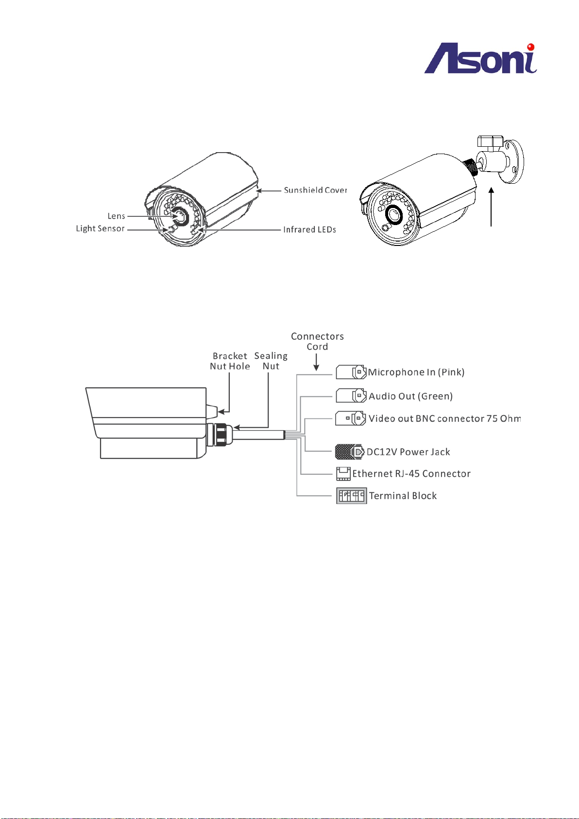
2Product Description ..................................................................................................................................................- 3 -
2.1 Hardware Description ............................................................................................................................................ - 4 -
3Setting up the Network Camera................................................................................................................................- 5 -
3.1 Read Before Use..................................................................................................................................................... - 5 -
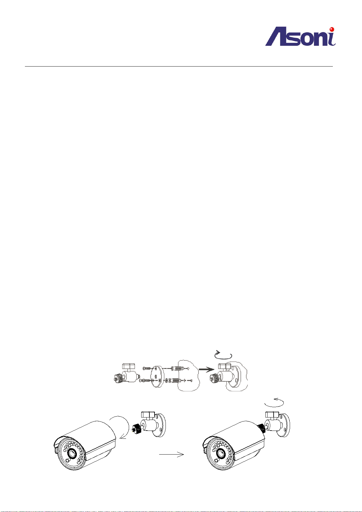
3.2 Hardware Installation Steps ................................................................................................................................... - 5 -
3.3 Open the Housing................................................................................................................................................... - 6 -
3.4 Using the Micro SD Card ........................................................................................................................................ - 6 -
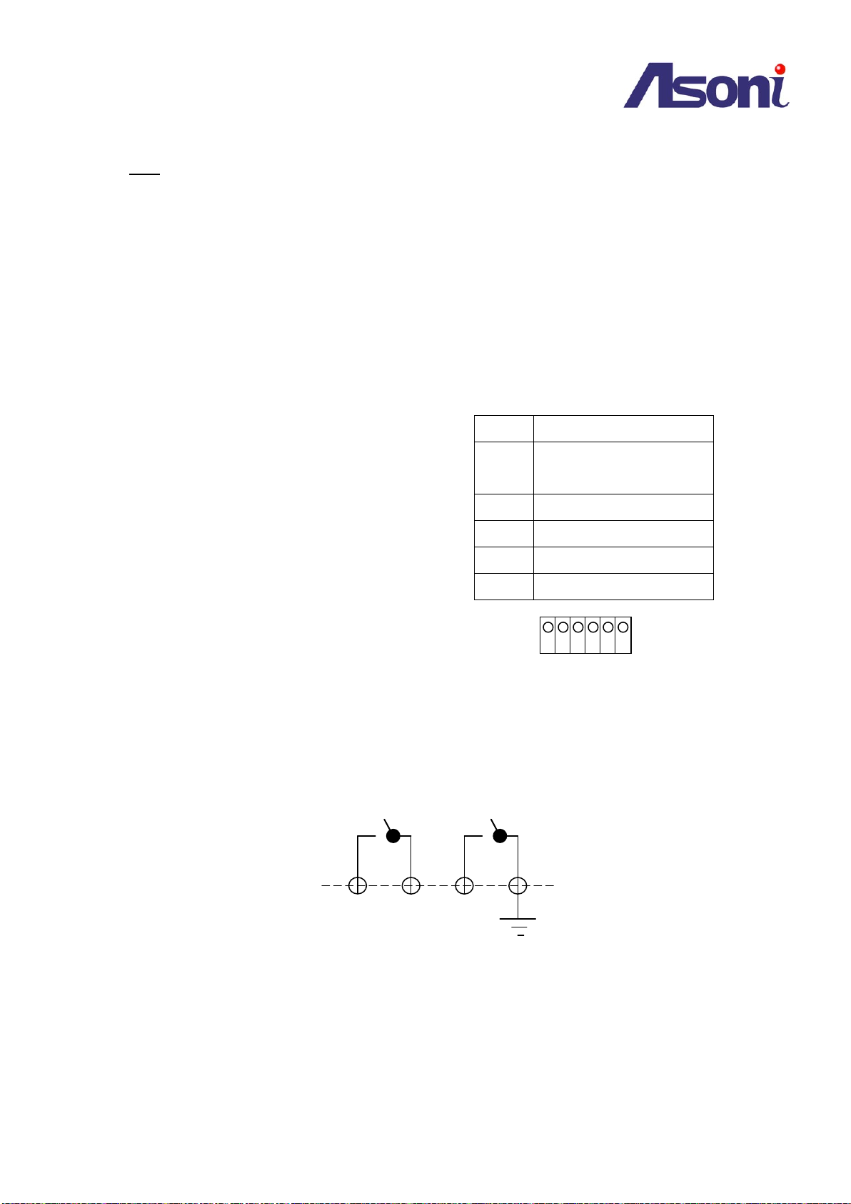
3.5 Using the Terminal Block........................................................................................................................................ - 7 -
3.6 Re-install the Housing ............................................................................................................................................ - 9 -
3.7 Network Connection for PoE/Non-PoE Cameras ................................................................................................. - 10 -
3.8 Using the Network Camera for the first time....................................................................................................... - 11 -
4Accessing the Network Camera ..............................................................................................................................- 12 -
4.1 Find Camera ......................................................................................................................................................... - 12 -
4.2 Before Assigning an IP Address ............................................................................................................................ - 12 -
4.3 Assigning the IP address to the network camera ................................................................................................. - 13 -
4.4 Access the camera from the browser .................................................................................................................. - 14 -
4.5 The Live View Page............................................................................................................................................... - 16 -
4.6 iPhone Camera Viewer......................................................................................................................................... - 18 -
5Configuring the camera...........................................................................................................................................- 19 -
5.1 Video Settings ...................................................................................................................................................... - 19 -
5.2 Camera Settings ................................................................................................................................................... - 23 -
5.3 Storage Settings ................................................................................................................................................... - 27 -
5.4 Event Settings....................................................................................................................................................... - 30 -
5.5 Network Settings.................................................................................................................................................. - 40 -
5.6 System Settings .................................................................................................................................................... - 45 -
6Troubleshooting .....................................................................................................................................................- 49 -
6.1 Factory Default..................................................................................................................................................... - 49 -
6.2 Viewing the camera from a remote location ....................................................................................................... - 49 -
7Frequently Asked Questions ...................................................................................................................................- 53 -

- 3 -
1Overview
This camera is a high-end 2 MegaPixel Bullet Network Camera, which is designed for professional outdoor security
applications. This network camera is equipped with removable IR-cut filter and Infrared LED, and provides
outstanding day and night performance. It comes with a 2 MegaPixel CMOS Sensor, with a maximum resolution of
1600 x 1200, delivering sharp image quality. Furthermore, the dPTZ (Digital Pan/Tilt/Zoom) function allows user to
navigate any area of the monitored image with maintained sharp resolution. With unique features, this network
camera provides an ideal solution for surveillance and monitoring
2Product Description
Key features
1. H.264 High Profile / MJPEG Dual Compression:
Offers the user the option to select H.264 or MJPEG compression.
2. ONVIF ® Compliant for Easy Integration & Fast Deployment:
Web services built-in with international standard protocols, integration cycles have been reduced and
deployment has become easier. ( Contact your distributor for documentation).
3. Multiple video profiles simultaneously for streaming:
Streams up to 8 independent streams with multiple profiles.
Different configurations can be set according to the bandwidth that is available from the network.
4. Infrared LED for Day & Night Model, 20 Meters
There are 24 infrared LEDs located underneath the transparent cover.
5. Micro SD Card Slot for Local Storage
For saving snapshots that can be later checked by the user, upon events occurred during motion
detection.
6. Analog Video BNC Out for Video Redundancy on Analog devices
The Network Camera has a video output with analog signal that allows connecting to analog monitors.
7. Alarm In & Alarm Out for connecting Alarm Devices
The Network Camera comes with a Terminal Block for connecting alarms to execute actions upon it.
8. Power-over-Ethernet IEEE 802.3 af for simplified connection ( Optional)
Make installations simple with connecting only one cable without additional powering sources.
9. Weather-proof IP66 rated housing
The camera can be shielded from rain and dust.

- 4 -
2.1 Hardware Description
Video out BNC Connector (75 Ohm)for connecting analog monitor
Power Jack 12VDC for connecting AC/DC power adapter
Ethernet RJ45 Port for network connection
Terminal Block (6 pins) for Digital In/Out and load default activation
Microphone In (Pink) for connecting a microphone
Audio Out (Green) for connecting a speaker
Bracket

- 5 -
3Setting up the Network Camera
3.1 Read Before Use
The use of surveillance devices may be prohibited by law in your country. The Network Camera is not only a
high-performance web-ready camera but can also be part of a flexible surveillance system. It is the user’s
responsibility to ensure that the operation of such devices is legal before installing this unit for its intended use.
It is important to first verify that all contents received are complete. Take note of the warnings in the Quick
Installation Guide before the Network Camera is installed; then carefully read and follow the instructions in the
Installation chapter to avoid damage due to faulty assembly and installation. This also ensures the product is
used properly as intended. It is designed for various applications including video sharing, general
security/surveillance, etc.
3.2 Hardware Installation Steps
After unpacking the package and identifying its parts, assemble the network camera to run the device for the
first time.
It is recommended set up the camera before installing it to the intended location.
The following instructions will consist of basic steps that will help you through the hardware preparation.
Other required devices before powering up the Network Camera:
1. Personal Computer or Laptop; and
2. Network Hub or Switch and 2 (two) pieces of Ethernet Cable; or
3. 1(one) piece of Crossover Ethernet Cable
STEPS:
1. Attach the bracket that comes in the package to the Bracket Nut Hole
2. Connect the Ethernet Plug to the Network Connector RJ-45 from the device
Plug the Power Jack to the Power Connector (For Network Cameras that are Power-over-Ethernet
supported, the Power Adapter is not necessary)
3. After the Power Connector is plugged in, the Network Camera will boot up.
4. Wait a few seconds for the Network Camera to startup
Assemble the Bracket

- 6 -
3.3 Open the Housing
The Micro SD card slot and factory default button are located inside the Network Camera. It’s required to
open the back cover of the camera and use them.
Note:
1. Once the back cover has been Deleted, you will find a rubber ring slightly attached to the inner
side of the body of the Network Camera. Don’t lose the rubber ring as it is required to prevent
water getting into the camera, as well as for a proper sealing and fitting of the back cover.
2. An additional rubber ring is included in package for spare.
3. It is suggested to reduce the opening of the camera since the unit is intended for outdoor usage.
4. It is recommended the contents of the card be read using from a remote connection. Please refer
to the section “5.3 Storage Settings”.
3.4 Using the Micro SD Card
The network camera comes with a Micro SD card slot to allow users insert a Micro SD
card to save snapshots and videos into it. Refer to Chapter 5) Configuring the camera,
Storage Settings and Event Settings.
Before plugging / unplugging Micro SD card into / from the slot, it’s recommended to turn
the device off.
Note:
We will not take the responsibility of the damage which made by user when user didn't assembly
Rubber Ring
Network Camera body
Screws
Screws
Back Cover
Micro SD slot
Rear View
Factory Default Button

- 7 -
properly after installing Micro SD card, and caused the unit's waterproof function failed.
Note:
1. The device does not support Hot-Swapping function.
2. Tweezers is recommended to help insert the Micro SD card.
3. This unit supports minimum 2GB and max 32GB Micro SD/SDHC card and Class 6 or higher for
smooth operation.
3.5 Using the Terminal Block
The network camera comes with a Terminal Block
that can offer multiple functions to the user:
Pin 1 ~ 4: Intended for triggering and receiving alarms
for the Event Configuration feature.
Pin 5, 6: Terminal block also provides 2 pins, Pin 5 and
6, for “load default”. With 2 wires connected to Pin 5
& 6, keep 2 wires in touch until System LED fast
flashing. Then, separate them to activate “load
default”.
Connecting Alarm devices
Connect Pin 1 and Pin 2 for an external relay device such as an alarm that expects to be activated.
Connect Pin 3 and Pin 4 for an external Triggering device for sending a signal into the Network
Camera.
Refer to Chapter 5) Configuring the camera, Event Settings for more references on
how to use the even trigger and alarm to perform tasks such as taking snapshots and uploading
images.
Load default
With 2 wires connected to Pin 5 & 6, keep 2 wires in touch (or close circuit) until System LED fast
flashing. Then, separate (or open) them to activate “load default”.
Pin 1 COM (Relay Common)
Pin 2 D-OUT (Relay Normal
Open/Close)
Pin 3 D-IN (Digital Input)
Pin 4 GND (Ground)
Pin 5 GND (Ground)
Pin 6 DEFAULT (Load Default)
Terminal Block Definition
1 2 3 4 5 6
Pin 1
Pin 2
Pin 3
Pin 4

- 8 -
Pin 6
Pin 5

- 9 -
3.6 Re-install the Housing
When finishing Micro SD card installation or factory default, please re-install the parts as the following order (A
to E) and end up with tightly fastening the screws.
A). To ensure water-proof function, do certainly locate the waterproof rubber in place (see the right figure)
before installing the back cover.
B). Put the PCBA into the camera body.
C). Put the desiccant bag in.
D). Install the back cover.
E). Fasten the screws tightly.
Note:
1. There is one additional unopened desiccant (silica gel) inside the housing for spare.
2. To ensure fog-proof function, do replace the desiccant bag with a new one, when it’s necessary to
re-install the camera. An unopened silica gel bag can last about 3 months, however, the durability could be
shortened under severe environment.
3. Silica Gel is the recommended desiccant type to ensure fog-proof function. If the desiccant bag is run out,
please purchase and replace with this type.

- 10 -
3.7 Network Connection for PoE/Non-PoE Cameras
The Network Camera comes as an optional model which supports Power-over-Ethernet (PoE).
Using Power-over-Ethernet as power supplying mode, takes advantage of having a simple connection, with
only one Ethernet Cable to act like Data and Power transmission. And it is not necessary to use any Power
Adapter since the powering will be done directly through the Ethernet Connector.
Below a comparison between a Regular Ethernet connection and a connection using Network Camera with
built-in Power-over-Ethernet.
Power Adapter
Power Adapter
ADSL Modem
Network Camera with
Power-over-Ethernet
Broadband Router
POE
Switch
Ethernet cable Ethernet cable Ethernet cable
POE Switch & POE Network Camera
Power Adapter
Power Adapter
Power Adapter
ADSL Modem
Network Camera
Broadband Router
Hub / Switch
Ethernet cable Ethernet cable Ethernet cable
Non-POE Connection
Power Adapter
Power Adapter
Power Adapter
ADSL Modem
Network Camera with
Power-over-Ethernet
Broadband Router
Hub / Switch
Ethernet
cable Ethernet
cable Ethernet
cable
POE Single Injector & POE Network Camera
POE Injector
Ethernet
cable
Note:For safety precautions, when using a PoE Video Encoder, ensure that the standard Power
Connector has been Deleted before plugging the Ethernet cable (which is attached on the other end to a
PoE Hub / Switch).

- 11 -
3.8 Using the Network Camera for the first time
The Network Camera is a network device and its use should be straightforward for those who have basic
networking knowledge. Making the initial steps for setting up the network camera will be based on a simple
network connection.
Option 1
Connect the network camera to a HUB / Switch which is connected to a PC
Option 2
Connect the network camera directly to a PC with a crossover cable.
After the network camera has its activity lights on, use the PC for setting up the IP Address of the Network
camera. Refer to the section of “Accessing the Network Camera” at the next page for detailed instructions.
Hints: Possible Network Configurations in your network infrastructure
1. Configuration 1
Internet Access: ADSL or Cable Modem
IP address: One real IP or one dynamic IP
Connection Type: Only the Network Camera connects to the internet
For fixed real IP, set up the IP into the Network camera. For dynamic IP, start PPPoE.
2. Configuration 2
Internet Access: ADSL or Cable Modem
IP address: More than one real IP or one dynamic IP
Connection Type: The Network Camera and PC connect to the internet
Device needed: Switch Hub
For fixed real IP, set up the IP into the Network camera and PC. For dynamic IP, start
PPPoE.
3. Configuration 3
Internet Access: ADSL or Cable Modem
IP address: one real IP or one dynamic IP
Connection Type: The Network Camera and PC connect to the internet
Device needed: IP sharing such as Hub / Switch and a Router
Use virtual IP, set up port forwarding in IP sharing.
(Suggestion: Refer to your Network Administrator if necessary for more information)

- 12 -
4Accessing the Network Camera
Before getting access to the Network Camera from user’s PC, it’s necessary to properly configure its network
setting. This camera uses 192.168.1.200 as the default IP address. If you would like to assign a new static IP
address, please install “CAM7 Series Device Search” from the CD-ROM, and then use this program to do that.
4.1 Find Camera
1. Once installed on the PC, click on [Start Menu >> All Programs >> Asoni >> Search Tooling >> Asoni CAM7
Series Device Search] to open the software.
2. The software automatically (or by clicking on “Search” button) displays cameras on the network. Identify
your camera by its MAC Address that is shown on the label of the camera.
3. Click on “Web” button or double-click on the identified camera item on the list to launch live viewing (it is
assumed that the network cable you’ve connected to your camera has provided a set of useable IP
address/subnet mask/Gateway), or click on “Config” button to configuring IP information.
4.2 Before Assigning an IP Address
Before assigning an IP address, make sure the Network Camera is powered on and correctly connected to the
network.
Obtain a LAN IP address not yet used and its related configuration from your network administrator.
The following will be required:
1. IP Address
2. Subnet Mask
3. Gateway
MAC Address: Each Network Camera has a unique Ethernet address (MAC address) shown on the label of the
Network Camera.
Hints: When assigning an IP Address
User can find necessary IP information by checking the current IP information of user’s host PC via Windows
command “ipconfig”:
-Click on Windows screen: the Start Menu >> All Programs >> Accessories >> Command Prompt.
-Type “ipconfig” at the command prompt to show the current IP information of user’s host PC.

- 13 -
For example,
C:\ >ipconfig
Windows IP Configuration
Ethernet adapter Local Area Connections:
Connection-specific DNS Suffix . : king-tech.com
IP Address. . . . . . . . . . . . : 192.168.1.102
Subnet Mask . . . . . . . . . . . : 255.255.255.0
Default Gateway . . . . . . . . . : 192.168.1.254
C:\ >
Then, use other IP address 192.168.1.xxx (1-253, except IP address of host PC 192.168.1.102), the same subnet
mask 255.255.255.0 and default gateway 192.168.1.254 for the network camera.
4.3 Assigning the IP address to the network camera
Select a Network Camera and click on “Setup”. Then, start to configure network settings, such as the following
fields:
IP Address / Subnet Mask / Gateway / DNS
Click on “Update” to apply the changes only by using administrator’s privilege (default user/password =
admin/admin).
To open the main page of the network camera, select your camera and click on “Web”.
* Remember to input a different
value for the last digits of IP address
from the “ipconfig”, ranging from 1
to 255.
Make sure you enter the same
values for Subnet Mask and Default
Gateway shown on your “ipconfig”
screen.

- 14 -
4.4 Access the camera from the browser
Start the IE browser, type the IP address of the network camera in the address field:
http://<IP of camera>
If the “HTTP Port” has been changed from “80”, type the URL as:
http://<IP of camera>:<HTTP Port>
Once the Network Camera is accessed, the Network Camera will request a Username and Password. The default
Username and Password is “admin” and “admin”.
Note: If “anonymous login” (see 5.6.2) is enabled, the Live View page will be shown without restriction. Or
please enter “admin/admin (default account/password)” to pass the authentication.
When the Network Camera is accessed via Internet Explorer, it will ask you to install the ActiveX component.
Note: during the webpage loading, you may be asked to allow the installation of Active X elements. Please allow
it to proceed.
Once get accessed, follow the instructions in the manual for the camera operation.
If the ActiveX installation doesn't start automatically, please follow below procedures to change security level
settings of your Internet Explorer browser.
Hints: Changing the root password
To avoid security breaches, it is recommended changing the Username and Password once the
device is set up to work. Refer to Chapter 5, Configuring the Camera, System Settings.

- 15 -
Kindly note that if you didn't install ActiveX and you will not be able to see the Live view image. Please make
sure to install it first.
To adjust the Security Options of Internet Explorer follow the below instructions:
Internet Explorer > Tools > Internet Options > Security Tab > Custom Level > Security Settings > Download
unsigned ActiveX controls > Select “Enable” or Prompt.
Internet Explorer > Tools > Internet Options > Security Tab > Custom Level > Initialize and script ActiveX controls
not marked as safe > Select “Enable” or Prompt.
When popup the following dialogue box, click “Yes”

- 16 -
Then, the Live View page will be opened. Click on the “Setup” link of the Live View page to change the
configurations of the network camera.
4.5 The Live View Page
Video Source: The Stream Profile drop-down list allows you to select a customized or pre-programmed stream
Select user interface
language: English,
traditional Chinese and
simplified Chinese

- 17 -
profile on the Live View page. Refer to Streaming Settings of this chapter for more references.
Rotation: allows the rotation of the video to be viewed in an angle of 0 (current), 90, 180 or 270 degrees at a
clockwise direction.
Full Screen: Maximizes the video to be displayed at a full screen size.
Real Size: Displays the real size of the video; (the initial video size will be adjusted to fit your monitor,
while the real size could be bigger than it is being shown in the monitor).
Listen: allows the user from the PC listen the location where the camera is set.
Talk: allows the user from the PC talk remotely to the camera, for which the speaker will emit the
voice.
Manual Record: Once pressed, it records and saves the currently viewed video the indicated path
below. To stop the recording, press back the Recording button.
Snapshot:once clicked, it will take a snapshot and save it to the indicated path below.
Path Button: Sets the location where the video and snapshot are saved to. To change the location,
click on the button and select the desired path.
FPS Frames per Seconds: Indicates the quantity of frames displayed in the current view.
BPS Bit per second: Indicates the bandwidth allocated for the streaming of the live video.
Notes for Windows 7 Users:
For Window 7 users, the operating system requires users to configure the Internet Explorer administrator

- 18 -
setting before the recording and snapshot functions can be enabled.
4.6 iPhone Camera Viewer
The network camera provides “iPhone Camera Viewer” for user to monitor via iPhone.
Once LAN or internet settings are completed on iPhone, as below, user can monitor via iPhone web browser by
just entering the IP address (or domain name) of the network camera.
1). Go to “Settings” to complete network settings, such as WiFi, network (DCHP, BootP, or Static IP).
2). Go to “Safari” and enter the IP address (or domain name) of the network camera, which is followed by an
authentication procedure (user/password = admin/admin). Then, Live video page “iPhone Camera Viewer” can
be seen.

- 19 -
5Configuring the camera
Video Main features and advanced configurations of video streaming.
Camera Image adjustments such as brightness, white balance and more.
Storage Displays information of the files located in the Micro SD card (if any).
Event Smart features for event settings to send emails, snapshots and more.
Network Network configuration for the network camera and Event features.
System Firmware version information and upgrade, User access management, and system information.
5.1 Video Settings
The video settings page contains setting for the streaming
5.1.1 General Settings

- 20 -
Video General Setting:
The Network Camera has in total 8 independent and simultaneous streams which can be used.
Your requirements and the properties of your network will determine the type you use.
The Live View page in the network camera provides access to a list of streams which are set in this page.
They can either be H.264 or Motion JPEG video streams that are configured according to each user’s need.
Other applications and clients can also access these video streams/images directly, without going via the
Live View page.
Stream Types: Stream 1, 3, 5 and 7: H.264
Stream 2, 4, 6 and 8: MJPEG
URL ID: Sets the name for the streaming; input an appropriate name to indicate the stream type
which is being used.
Video Mode: CBR:512 Kbps ~ 4Mbps – Increase CBR to increase the picture quality; or vice versa
VBR:The network camera will adjust itself automatically to fit the best picture quality
through the bandwidth provided by the network. The balance between VBR and network
bandwidth will affect picture quality.
Quality Level: There are three levels to adjust: Best, Good and Standard
The higher the quality is, the more bandwidth it will use for streaming the video.
Resolution: You can set up a different video resolution for different viewing devices.
Note that a larger frame size takes up more bandwidth.
GOP: GOP stands for "Group of Pictures". The GOP is a group of successive pictures
within a coded video stream.
Frame Rate: This limits the maximum refresh frame rate per second. Set the frame rate higher for
smoother video quality.
Target Bit Rates: 512 Kbps ~ 4Mbps – Increase CBR to increase the picture quality; or vice versa.
Profile: Providing both of high profile and baseline profile. High profile can deliver better video
quality ,but it will cause network camera have larger load relatively.
Notes for Stream 1 (H.264) HD:
When the Resolution is 1600x1200, the Frame Rate is “15”. When the Resolution is 1280x720, the Frame
Rate is 30.
This manual suits for next models
1
Table of contents
Other Asoni Network Camera manuals