Aspect TDMHA.00 User manual

Transforming the way companies interact with their customers.®
Aspect®
Headset Adapter Installation Guide
TDMHA.00

© 2007-2008 Aspect Software, Inc. All Rights Reserved. Unauthorized Reproduction Prohibited By Law.
The content of this publication is furnished for informational use only, is subject to change without notice, and should not be construed as a
commitment by Aspect Software, Inc. Aspect Software, Inc. assumes no responsibility or liability for any errors or inaccuracies that may
appear in this publication. Aspect Software, Inc. reserves the right to change information in this publication without notice, as a result of
product enhancements or other reasons.
Aspect, Aspect Software, Aspect CallCenter, Spectrum, Aspect Customer Self Service, Unison, Unison Predictive Dialer, Conversations,
Conversations Predictive Dialer, Enterprise Contact Server, Contact Server, Unified IP, Uniphi Suite, PerformanceEdge, eWorkforce
Management, RightForce, RightForce Workforce Management, Analyzer, Campaign Optimizer, Enterprise Campaign Manager, Aspect
Quality Management, Aspect Performance Management, Unified Command and Control, DataMart, and LYRICall are either trademarks or
registered trademarks of Aspect Software, Inc., in the United States and/or other countries. Use of any Aspect Software, Inc. trademark is
subject to express written pre-approval from Aspect Software, Inc. Any other brands, product names, company names, logos, trademarks,
and/or service marks used in this publication are the property of their respective owners.
The works of authorship contained in this publication, including but not limited to all design, text and images and the software described
herein, are owned, except as otherwise expressly stated, by Aspect Software, Inc., or its affiliates or licensors. The entire contents of this
publication are protected by United States’ and worldwide copyright laws and treaty provisions. In accordance with these terms, except as
stated above, you may not copy, reproduce, modify, use, republish, upload, post, transmit or distribute in any way material from the
publication. Further, you may not copy, modify or display any of Aspect Software, Inc.’s or its affiliates’ trademarks, tradenames or logos
appearing in this publication in any way without Aspect Software, Inc.’s express written consent. Aspect Software, Inc. assumes no
responsibility or liability for any errors or inaccuracies that may appear in this publication. Except as permitted by such license, no part of
this publication may be reproduced, stored in a retrieval system, or transmitted, in any form or by any means, electronic, or otherwise,
without the prior written permission of Aspect Software, Inc.
RESTRICTED RIGHTS LEGEND
This publication is provided with “Restricted Rights”. No part of this publication may be photocopied, reproduced or transmitted, in any
form or by any means, without the prior written consent of Aspect Software, Inc. Use, duplication, or disclosure by the United States
Government is subject to the restrictions set forth in DFARS 252.227-7013 (c)(1)(ii) and FAR 52.227-19. Use of the materials by the
Government constitutes acknowledgement of Aspect’s proprietary rights in them. Aspect Software, Inc. is located at 300 Apollo Drive,
Chelmsford, MA 01824, USA.
NO WARRANTY
THE CONTENTS OF THIS PUBLICATION ARE PROVIDED “AS IS” WITHOUT WARRANTY OF ANY KIND, EITHER EXPRESS
OR IMPLIED, INCLUDING, BUT NOT LIMITED TO, THE IMPLIED WARRANTIES OF QUALITY, MERCHANTABILITY,
FITNESS FOR A PARTICULAR PURPOSE, OR NON-INFRINGEMENT.
ASPECT SHALL NOT BE LIABLE FOR ANY DAMAGES SUFFERED AS A RESULT OF USING THE CONTENTS OF THIS
PUBLICATION. IN NO EVENT SHALL ASPECT BE LIABLE FOR ANY INDIRECT, PUNITIVE, SPECIAL, INCIDENTAL, OR
CONSEQUENTIAL DAMAGE (INCLUDING LOSS OF BUSINESS, REVENUE, PROFITS, USE, DATA OR OTHER ECONOMIC
ADVANTAGE) HOWEVER IT ARISES, WHETHER FOR BREACH OR IN TORT, EVEN IF ASPECT HAS BEEN PREVIOUSLY
ADVISED OF THE POSSIBILITY OF SUCH DAMAGE. BECAUSE SOME JURISDICTIONS PROHIBIT THE EXCLUSION OR
LIMITATION OF LIABILITY FOR CONSEQUENTIAL OR INCIDENTAL DAMAGES, THE ABOVE LIMITATION MAY NOT
APPLY TO YOU.
PROGRAMMING AND USE OF PRODUCTS
THE PRODUCTS DESCRIBED IN THIS DOCUMENTATION CAN BE USED AND PROGRAMMED IN A WIDE VARIETY
OF WAYS BASED UPON THE REQUIREMENTS OF YOUR PARTICULAR TECHNOLOGY ENVIRONMENT AND
BUSINESS NEEDS. NOTWITHSTANDING THE USE OF EXAMPLES IN THE DOCUMENTATION OR THE PROVISION OF
PROFESSIONAL SERVICES BY ASPECT, ASPECT RESELLERS OR ANY THIRD PARTY ENGAGED BY ASPECT, IT IS IN
ALL CASES THE USER'S RESPONSIBILITY TO ENSURE THAT THE PRODUCTS ARE PROGRAMMED AND USED IN
ACCORDANCE WITH ALL APPLICABLE LAWS AND REGULATIONS AND IN A MANNER THAT DOES NOT VIOLATE
THE INTELLECTUAL PROPERTY AND OTHER RIGHTS OF ANY THIRD-PARTY.
Part Number: 3205-10084B
Date: April 22, 2008

Headset Adapter Installation Guide
Table of Contents
About this Guide ................................................................................................................. 1
Intended Audience .............................................................................................................. 1
FCC Compliance.................................................................................................................. 1
Regulatory Compliance ...................................................................................................... 1
Intended Use........................................................................................................................ 2
1. Getting Started ............................................................................................................. 3
1.2 Functional Block Diagram .......................................................................................3
2. Overview ....................................................................................................................... 4
2.1 Features................................................................................................................... 4
2.2 Rear View................................................................................................................ 5
2.3 Switch Settings........................................................................................................5
3. Enable Switches Jumper............................................................................................. 7
3.1 TDM, 8 Pin RJ-45 Connector Pin-Out.....................................................................7
3.2 DC IN, 5 Pin DIN Connector Pin-Out.......................................................................7
3.3 HS 0–11, 50 Pin Female Amphenol Telco Connector Pin-Out................................ 8
3.4 HS 24–29, 50 Pin Female Amphenol Telco Connector Pin-Out.............................. 9
4. Rules for Cabling the TDM Headset Adapter........................................................... 10
4.1 Headset Wiring Diagram for Headsets 0 Through 11............................................. 10
4.2 Headset Wiring Diagram For Headsets 12 Through 23.......................................... 12
4.3 Headset Wiring Diagram For Headsets 24 Through 29.......................................... 13
5. Cable and Accessory Selection Guide..................................................................... 14
6. Category 5 UTP E1 Crossover Cable Drawing......................................................... 15
7. Category 5 Shielded E1 Crossover Cable Drawing................................................. 16
8. Power Supply ............................................................................................................. 17
8.1 Power Supply Requirements for the TDMHA........................................................ 17
9. Recommended Headset............................................................................................. 17
9.1 Physical Characteristics of the TDMHA..................................................................17
10. Environmental Requirements................................................................................ 17
4-22-2008 3205-10084B Page i

Headset Adapter Installation Guide
4-22-2008 3205-10084B Page ii

Headset Adapter Installation Guide
4-22-2008 3205-10084B Page 1
About this Guide
The Headset Adapter Requirements and Operations Guide details the functional operation
and requirements for direct connect of the TDMHA-00 Headset Adapter to the Aspect
Software Digital Communications Processor, Model DCP-00. The TDMHA-00 Headset
Adapter is intended only for use with the Aspect Software DCP-00.
Intended Audience
This guide is designed for Aspect Software system users and supervisors who are familiar
with the particular contact center environment in which Aspect products are installed.
Readers are required to have a basic understanding of and familiarity with the Microsoft
Windows operating system as well as an understanding of sophisticated software
applications such as Ensemble, Unison, EnsemblePro, Conversations, and Unified IP.
If you are a new Aspect Software user, please contact Aspect University for the latest
training course information.
Internet: hftp://www.Aspect.com
Email:[email protected]
FCC Compliance
This equipment has been tested and found to comply with the limits for a Class A digital
device, pursuant to Part 15 of the FCC Rules. These limits are designed to provide
reasonable protection against harmful interference when the equipment is operated in a
commercial environment. This equipment generates, uses, and can radiate radio frequency
energy and, if not installed and used in accordance with the instructions, may cause harmful
interference to radio communications. Operation of this equipment in a residential area is
likely to cause harmful interference. Users will be required to correct the interference at their
own expense.
Changes or modifications not expressly approved by the party responsible for
compliance could void the user's authority to operate the equipment.
This Class A digital apparatus complies with Canadian ICFS-003
Cet appareil numeric de la classe A est conforme a la norme NMB-003 du
Canada.
Regulatory Compliance
The TDMHA has been tested to, and conforms to, the following:
CE Mark (for safety)
Low Voltage Directive and IEC 950 Amendments 1, 2, 3, and 4
UL/cUL Listed

Headset Adapter Installation Guide
4-22-2008 3205-10084B Page 2
CE Mark (EMC) - Conducted Emissions, Radiated Emissions, Electrostatic
Discharge, Radiated Immunity,
Power Leads Fast Transients, I/0 Leads Fast Transients, and RFI Power.
Intended Use
•The TDMA-00 Headset Adapter is intended to be used only with the Aspect Software
DCP-00. Refer to the “Overview” section of this document.
•The TDMA-00 Headset Adapter does not connect directly to the Public Switch
Telephone Network (PSTN).
•The TDMA-00 Headset Adapter is intended to be used within the same building as
the DCP-00 and shall not be used in an inter-building campus environment.

Headset Adapter Installation Guide
1. Getting Started
1.2 Functional Block Diagram
4-22-2008 3205-10084B Page 3

Headset Adapter Installation Guide
2. Overview
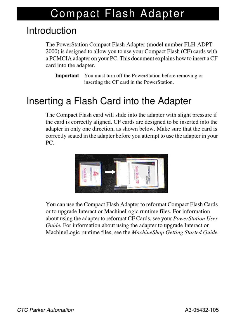
The TDM Headset Adapter (TDMHA) converts TDM digital data to analog audio data for use
with Standard type 2500 telephone headsets.
The TDMHA connections consist of one TDM 8-pin modular connector, one power
connector for an external power supply, and three 25-pair Amphenol connectors for headset
connections.
This is a conceptual wiring diagram for reference only. Each customer site will differ,
depending on existing wiring.
Note: To reduce noise interference induced into the analog wiring (the connections between
the TDMHA and the mod jacks for the operator's headset) keep the total length of this wiring
as short as possible. If you need more length, it is preferable to extend the length of the
cable between the DCP and the TDMHA (digital cable #883275R) up to the limit of 2000
feet. The standard length of the digital cable (#883275R) is 20 feet. Please contact your
Aspect Sales Person if you need a different length.
2.1 Features
30 agent headsets in a single unit
Each unit can be placed up to 610 meters away from the DCP
Note: The TDMA-00 Headset Adapter is intended to be used within the same building as
the DCP-00 and shall not be used in an inter-building campus environment.
Improved audio cabling interface reduces cross-talk
4-22-2008 3205-10084B Page 4

Headset Adapter Installation Guide
2.2 Rear View
2.3 Switch Settings
Switch 1 (FREER) is used for factory testing only and must be set to the down position for
normal operation.
The up position will set the unit in a free-run (non clock extract) mode. This is useful for
testing the units without using a DCP. By connecting two of the units together, one in normal
mode and the other in free-run mode, the two units can communicate with each other. The
unit running in normal mode will extract the required synchronizing clocks from the free-
running unit and the two units will remain synchronized.
Headsets connected to the units will then function properly allowing audio communications
between the two corresponding headsets of each unit. For example, the headset connected
headset port # 5 on the normal unit will communicate with the headset connected headset
port # 5 on the free-running unit.
Switch 2 (A - U) is used to select between A-law and u-law compression. In the down
position A-law is selected and in the up position u-law is selected.
Switch 3 (BIAS) is used to select the bias voltage to the headsets. In the down position the
bias voltage is approximately 3.3 volts. This position is only used for headsets requiring
reduced bias voltage to function or for headsets that do not require external power. In the up
position the bias voltage is approximately 9.4 volts. The up position is the default setting for
the currently recommended Plantronics headset/amplifiers.
4-22-2008 3205-10084B Page 5

Headset Adapter Installation Guide
4-22-2008 3205-10084B Page 6
Switch 4 (SIDTN) is used to enable and disable the sidetone feedback. In the up position, a
small amount of the user’s voice is returned to the user’s ear. The down position will
disable* the sidetone feedback.
Note: *This switch can be disabled with the internal enable/disable switch jumper.
Switches 5 and 6 (XSET2, XSET1) are used to set the transmitted output audio level from
the headset microphones to the CODECs. This is useful for headset amplifiers that do not
have an adequate range of adjustment. Caution should be exercised with the settings of
these switches. Crosstalk and noise, from the cabling, may be noticeable in longer cables
with the higher level switch settings. For the best results, adjust the headset amplifier
microphone gain adjust to the highest usable setting and then adjust the (XSETx) switches
for the lowest usable level. This will reduce the cable noise and crosstalk to a minimum.
Note: This switch can be disabled with the internal enable/disable switch jumper.
XSET2 XSET1 AUDIO GAIN
UP UP = + 4 DB
UP DOWN = 0 DB default *
DOWN UP = - 5 DB
DOWN DOWN = - 10 DB
* Note: This is the value that will be observed when the internal jumper is in the disable
switches position.
Rotary switch (RSET) is used to set the receive input audio level to the users headsets. This
is useful for headset amplifiers that do not have an adequate range of adjustment. Caution
should be exercised with the settings of these switches. Crosstalk and noise, from the
cabling, may be noticeable in longer cables with the higher level switch settings. For the
best results, adjust the headset amplifiers earphone volume adjust to the highest setting
and then adjust the (RSET) switch for the lowest usable level. This will reduce the cable
noise and crosstalk to a minimum.
Note: This switch can be disabled with the internal enable/disable switch jumper.
RSET AUDIO GAIN
0 = - 4 DB
1 = - 2 DB
2 = 0 DB default *
3 = + 2 DB
4 = + 4 DB
5 = + 6 DB
6 = + 8 DB
7 = + 10 DB
8 = + 12 DB
9 = + 14 DB
* Note: This is the value that will be observed when the internal jumper is in the disable
switches position.

Headset Adapter Installation Guide
3. Enable Switches Jumper
This jumper is used to enable or disable the externally accessible audio gain and side tone
switches. This is useful for countries that restrict end user accessible adjustments to the
audio levels over their Telco networks. This is a 3 pin header with a movable shunt
connector. When the shunt is placed across pins 1 and 2, the SIDTN, XSET2, XSET1 and
RSET switches are disabled and serve no function. In this state there is no side tone and
the transmit and receive gains are set to 0 DB (the default settings). When the shunt is
placed across pins 2 and 3, the SIDTN, XSET2, XSET1 and RSET switches are enabled
and will function as described in the SWITCH SETTINGS section of this document.
3.1 TDM, 8 Pin RJ-45 Connector Pin-Out
3.2 DC IN, 5 Pin DIN Connector Pin-Out
4-22-2008 3205-10084B Page 7

Headset Adapter Installation Guide
3.3 HS 0–11, 50 Pin Female Amphenol Telco Connector Pin-Out
1 = EARPHONE 12 (OUTPUT)
2 = MICROPHONE 12 (INPUT)
3 = EARPHONE 13 (OUTPUT)
4 = MICROPHONE 13 (INPUT)
5 = EARPHONE 14 (OUTPUT)
6 = MICROPHONE 14 (INPUT)
7 = EARPHONE 15 (OUTPUT)
8 = MICROPHONE 15 (INPUT)
9 = EARPHONE 16 (OUTPUT)
10 = MICROPHONE 16 (INPUT)
11 = EARPHONE 17 (OUTPUT)
12 = MICROPHONE 17 (INPUT)
13 = EARPHONE 18 (OUTPUT)
14 = MICROPHONE 18 (INPUT)
15 = EARPHONE 19 (OUTPUT)
16 = MICROPHONE 19 (INPUT)
17 = EARPHONE 20 (OUTPUT)
18 = MICROPHONE 20 (INPUT)
19 = EARPHONE 21 (OUTPUT)
20 = MICROPHONE 21 (INPUT)
21 = EARPHONE 22 (OUTPUT)
22 = MICROPHONE 22 (INPUT)
23 = EARPHONE 23 (OUTPUT)
24 = MICROPHONE 23 (INPUT)
25 = NO INTERNAL CONNECTION
26 = EARPHONE 12 RETURN
27 = MICROPHONE 12 RETURN
28 = EARPHONE 13 RETURN
29 = MICROPHONE 13 RETURN
30 = EARPHONE 14 RETURN
31 = MICROPHONE 14 RETURN
32 = EARPHONE 15 RETURN
33 = MICROPHONE 15 RETURN
34 = EARPHONE 16 RETURN
35 = MICROPHONE 16 RETURN
36 = EARPHONE 17 RETURN
37 = MICROPHONE 17 RETURN
38 = EARPHONE 18 RETURN
39 = MICROPHONE 18 RETURN
40 = EARPHONE 19 RETURN
41 = MICROPHONE 19 RETURN
42 = EARPHONE 20 RETURN
43 = MICROPHONE 20 RETURN
44 = EARPHONE 21 RETURN
45 = MICROPHONE 21 RETURN
46 = EARPHONE 22 RETURN
47 = MICROPHONE 22 RETURN
48 = EARPHONE 23 RETURN
49 = MICROPHONE 23 RETURN
50 = NO INTERNAL CONNECTION
4-22-2008 3205-10084B Page 8

Headset Adapter Installation Guide
3.4 HS 24–29, 50 Pin Female Amphenol Telco Connector Pin-Out
1 = EARPHONE 24 (OUTPUT)
2 = MICROPHONE 24 (INPUT)
3 = EARPHONE 25 (OUTPUT)
4 = MICROPHONE 25 (INPUT)
5 = EARPHONE 26 (OUTPUT)
6 = MICROPHONE 27 (INPUT)
7 = EARPHONE 27 (OUTPUT)
8 = MICROPHONE 27 (INPUT)
9 = EARPHONE 28 (OUTPUT)
10 = MICROPHONE 28 (INPUT)
11 = EARPHONE 29 (OUTPUT)
12 = MICROPHONE 29 (INPUT)
26 = EARPHONE 24 RETURN
27 = MICROPHONE 24 RETURN
28 = EARPHONE 25 RETURN
29 = MICROPHONE 25 RETURN
30 = EARPHONE 26 RETURN
31 = MICROPHONE 26 RETURN
32 = EARPHONE 27 RETURN
33 = MICROPHONE 27 RETURN
34 = EARPHONE 28 RETURN
35 = MICROPHONE 28 RETURN
36 = EARPHONE 29 RETURN
37 = MICROPHONE 29 RETURN
4-22-2008 3205-10084B Page 9

Headset Adapter Installation Guide
4-22-2008 3205-10084B Page 10
4. Rules for Cabling the TDM Headset Adapter
The TDM Headset Adapter shall be placed as close as possible to the agent positions
where headsets are employed. The recommended cable length between the TDMHA-00
Headset Adapter and the Agent Position is approximately 110 feet. The maximum length of
all combined cables between the TDMHA and the agent position where the headset is
employed shall be no more than 310 feet. The stated distance limitations are required for
good reliable agent position headset audio.
Category 5 (or better) twisted pair cables shall be used between the TDMHA and the agent
position headset.
The use of flat non-twisted silver satin telephone cables shall be avoided. They offer poor
isolation between transmit and receive pairs. If flat silver satin telephone cables are
employed, the physical length shall be no longer than 6 ft. If coach mode is intended, the flat
silver stain cords shall not to be used.
Category 5 (or better) twisted pair cables shall be used between the DCP and the TDMHA.
The maximum length of this cable shall be 2000 feet.
All TDMHA cables shall be isolated from other electrical wiring such as fluorescent lighting
fixtures; power transformers, transmitters and other electrical appliances that might cause
interference with the functionality of the TDMHA.
4.1 Headset Wiring Diagram for Headsets 0 Through 11
The total wire length shown shall not exceed 310 feet. All items are customer supplied.
Note: To reduce noise interference induced into the analog wiring (the portion of the wiring
between the headset adapter and the mod jack for the agent’s headset) keep the total
length of this wiring as short as possible. If you need more length, it is preferable to extend
the length of the cable between the DCP and the TDMHA (digital cable # 883275R) up to
the limit (2000 feet).

Headset Adapter Installation Guide
4-22-2008 3205-10084B Page 11

Headset Adapter Installation Guide
4.2 Headset Wiring Diagram for Headsets 12 Through 23
The total wire length shown shall not exceed 310 feet. All items are customer supplied.
Note: To reduce noise interference induced into the analog wiring (the portion of the wiring
between the headset adapter and the mod jack for the agent’s headset) keep the total
length of this wiring as short as possible. If you need more length, it is preferable to extend
the length of the cable between the DCP and the TDMHA (digital cable # 883275R) up to
the limit (2000 feet).
4-22-2008 3205-10084B Page 12

Headset Adapter Installation Guide
4.3 Headset Wiring Diagram for Headsets 24 Through 29
The total wire length shown shall not exceed 310 feet. All items are customer supplied.
Note: To reduce noise interference induced into the analog wiring (the portion of the wiring
between the headset adapter and the mod jack for the agent’s headset) keep the total
length of this wiring as short as possible. If you need more length, it is preferable to extend
the length of the cable between the DCP and the TDMHA (digital cable # 883275R) up to
the limit (2000 feet).
4-22-2008 3205-10084B Page 13

Headset Adapter Installation Guide
5. Cable and Accessory Selection Guide
1. ASPECT # 883275R-25 Category 5, 25 Ft, T1/E1 CROSSOVER CABLE supplied with
TDMHA.
Note: This cable and items 2 and 3 can be replaced with a single cable. See the
attached cable assembly drawings 883272 or 883275R.
2. RJ45 Modular Coupler (pin 1 to pin 1),
3. RJ45 Category 5, or better, Patch Cord (pin 1 to pin 1), 2000 feet maximum.
4. 25 pair Category 3 TELCO Cable with a MALE AMPHENOL connector on one end with
appropriate mating connector for interfacing item # 5. on the other end. Keep this cable as
short as possible (5 FEET or less is preferred).
5. Bunch block for punching down standard Category 3 (or better) twisted pair wiring or
other breakout interface connection block.
6. Category 5 (or better) twisted pair cabling to agent area Modular Jack interface (310 feet
max.). Shielded cable is preferred. Category 3 twisted pair cabling can be used for shorter
runs if it is not tightly bunched.
7. Agent area modular connection.
8. Category 5 (or better) twisted pair cables shall be used between the TDMHA and the
agent position headset. The use of flat non-twisted silver satin telephone cables shall be
avoided. They offer poor isolation between transmit and receive pairs. If flat silver satin
telephone cables are employed, the physical length shall be no longer than 6 ft. If coach
mode is intended, the flat silver stain cords shall not to be used.
9. RJ22 Modular Coupler/Reducer.
10. Customer provided headset amplifier.
11. Customer provided headset.
4-22-2008 3205-10084B Page 14

Headset Adapter Installation Guide
6. Category 5 UTP E1 Crossover Cable Drawing
4-22-2008 3205-10084B Page 15

Headset Adapter Installation Guide
7. Category 5 Shielded E1 Crossover Cable Drawing
4-22-2008 3205-10084B Page 16
Table of contents
