ASPEL CRG 200 User manual

Zabierzów, 19.05.2020, Edition I
ASPEL S.A.
PL 32-080 Zabierzów, os. H. Sienkiewicza 33
tel. +48 12 285 22 22, fax +48 12 285 30 30
www.aspel.com.pl
Operation Manual
Ergometer
CRG 200
v.5xx

Operation manual Ergometer CRG 200 v.5xx IU-AT-77-C_I_ENG
ASPEL S.A. 19.05.2020 Strona 2 z 31
Congratulations on your purchase of Ergometer CRG 200 which
has been developed as a result of years of research and experience
acquired due to direct contacts with our clients. Quality, durability
and efficiency are the characteristic features of Ergometer
CRG 200.
ASPEL also proposes a wide variety of medical equipment for ECG
Holter Systems as well as blood pressure meters, ABPM Systems,
spirometers, Exercises Stress Test Systems, electrocardiographs
with accessories, such as: trolleys, carry bags, ECG cables,
electrodes and ECG paper. You are gladly invited to visit our
website: www.aspel.com.pl.
Please, read the following manual carefully as it contains important
guidelines on safe installation, usage and upkeep of equipment. It
can also help to optimize the maintenance of the device.
For further consultation, please keep the following manual.

Operation manual Ergometer CRG 200 v.5xx IU-AT-77-C_I_ENG
ASPEL S.A. 19.05.2020 Strona 3 z 31
TABLE OF CONTENTS
1.
GENERAL INFORMATION..............................................................................................................4
1.1.
M
ANUFACTURER
’
S INSTRUCTIONS PERTAINING TO SAFETY OF OPERATION
........................................ 4
1.2.
W
ORKING
,
TRANSPORTATION AND STORAGE CONDITIONS
................................................................ 8
1.3.
S
YMBOLS MEANING
....................................................................................................................... 9
2.
DESCRIPTION OF ERGOMETER CRG 200.................................................................................10
2.1.
I
NTENDED USE
............................................................................................................................ 10
2.2.
G
ENERAL DESCRIPTION
............................................................................................................... 10
2.3.
E
RGOMETER
’
S APPEARANCE
....................................................................................................... 11
2.4.
F
UNCTIONS
................................................................................................................................. 14
2.5.
M
AIN TECHNICAL AND OPERATIONAL PARAMETERS
........................................................................ 14
2.6.
E
QUIPMENT
................................................................................................................................ 15
2.7.
M
ANUFACTURER AND DESIGNATION
............................................................................................. 16
3.
OPERATION OF ERGOMETER....................................................................................................17
3.1.
S
TART
-
UP OF THE DEVICE
............................................................................................................ 17
3.2.
P
ATIENT PREPARATION
................................................................................................................ 19
3.2.1.
Electrode placement for an exercise test .........................................................................20
3.2.2.
Electrode placement for cardiological rehabilitation.........................................................21
3.3.
U
SING
E
RGOMETER
.................................................................................................................... 21
4.
MAINTENANCE AND TECHNICAL SERVICE..............................................................................25
4.1.
C
LEANING
,
DISINFECTION
,
MAINTENANCE AND SERVICE
................................................................. 25
B
EFORE DISINFECTION
,
THE DEVICE AND ACCESSORIES SHOULD BE CLEANED
......................................... 25
4.2.
E
NVIRONMENTAL PROTECTION
..................................................................................................... 26
4.3.
C
USTOMER SERVICE
................................................................................................................... 26
4.4.
D
EALING WITH COMMON PROBLEMS
............................................................................................. 26
5.
ELECTROMAGNETIC COMPATIBILITY DECLARATION...........................................................27
6.
APPENDIX A – COOPERATION OF ERGOMETER CRG 200 WITH OTHER DEVICES............29

Operation manual Ergometer CRG 200 v.5xx IU-AT-77-C_I_ENG
ASPEL S.A. 19.05.2020 Strona 4 z 31
1. General information
1.1. Manufacturer’s instructions pertaining to safety of
operation
Instruction of use
•Before you start using the Ergometer, read carefully the Operation
Manual, PC operation manual and warranty card.
•We recommend you keep the Operation Manual with the device in order to
make it helpful with your routine usage and in case you have any
problems with the device.
•Operation Manual shall be helpful in proper operating and maintaining the
device.
•Following these instructions guarantees efficient functioning, reliability
and carrying out tasks expected from Ergometer by the user, as well as
safety during operation.
Staff
•Ergometer should always be used under supervision of qualified and
properly trained medical staff.
Patient
•Using the device with artificial cardiac pacemaker or other electric
stimulator does not cause danger neither for patient nor for operator.
Ergometer CRG 200 v.5xx
•Ergometer meets appropriate safety requirements and can be placed near
a patient (in an area of 1.5 m of free space surrounding a patient).
•Time of proper work of the device mainly depends on efficiency of its
elements, which in normal conditions are estimated to work for ten years.
When this time is exceeded, probability of damages resulting from
wearing down of elements increases, what can lead to device failure.
•All repairs should be performed in authorised service points of ASPEL
S.A.
•Making any modifications in the device is forbidden.
•Efficiency of Ergometer and its accessories should be checked
periodically. Every time any failures in functioning of the device are
noticed, you should contact with authorised service point of ASPEL.
Usage environment

Operation manual Ergometer CRG 200 v.5xx IU-AT-77-C_I_ENG
ASPEL S.A. 19.05.2020 Strona 5 z 31
•It is forbidden to use Ergometer in places which are damp or wet, exposed
to direct sunlight or rainfall, where dust may be present, in the vicinity of
flammable or explosive materials or in atmosphere polluted with
corrosion triggering factors.
•Ergometer is not suitable for use in an environment where flammable
gases or vapours may be present. It is also not suitable for use in oxygen
rich environment.
•Portable and mobile RF communication devices, e.g. mobile phones
(including peripherals such as antenna cables and antennas) should be
used in a distance no closer than 30 cm (12 in) to any part of the device,
including cables mentioned by the manufacturer. Otherwise, malfunction
of the device may occur.
•Ergometer and its accessories should not be placed near temperature
heat reservoirs such as stoves, heaters, etc.
Accessories
•Only accessories provided by the manufacturer are suitable to use with
Ergometer.
•Use of accessories or cables other than provided by the manufacturer
may lead to rise in electromagnetic emission or decline in electromagnetic
immunity of Ergometer and cause malfunctions.
Usage
•Inappropriate use of the device may be the cause of an accident.
•The device is not suitable to direct usage on open heart.
•The device is not adapted to interaction with surgical equipment of high
frequency.
•Conductive parts of electrodes, including neutral electrode, should not
touch neither metal parts, nor grounding.
•Operator cannot touch simultaneously patient and non-medical devices,
with which he can stay in contact.
•It is forbidden to train on faulty Ergometer – the device should not be
used until repaired.
•The patient’s cable should not be pulled, as it could cause mechanical or
electrical damage. Fold patient’s cable in a loose loop before storing.
•It is forbidden to use devices with faulty power supply cable.
•The patient’s cable should not be put in places exposed to damage, e.g.
puncture or stepping on. In case of mechanical damage of patient’s
cable, there is a risk of losing measurement’s accuracy and replacement
of the patient’s cable with a new one is necessary.
•During defibrillation, special precautions must be taken. Staff mustn't
touch neither defibrillated patient, nor devices connected to him or her.
•Please note that if a patient is connected to several devices, risk resulting
from build-up of leakage currents of each device should be taken into

Operation manual Ergometer CRG 200 v.5xx IU-AT-77-C_I_ENG
ASPEL S.A. 19.05.2020 Strona 6 z 31
consideration.
•Ergometer CRG 200 should be used only with external AC adapter
CRG200-M24 and power supply cable provided by the manufacturer. It is
forbidden to use other devices attached to external AC adapter's socket.
•Ergometer CRG 200 should be used only with ECG cable provided by the
manufacturer.
•To unplug Ergometer CRG 200 you should pull the plug of AC adapter
from a socket.
•It is forbidden to use a device with damaged power supply cable.
•Neither Ergometer CRG 200, nor external AC adapter CRG200-M24 should
be placed in a way that could cause any difficulties with unplugging the
device.
•Pay special attention for children staying unsupervised and keep them
away from the device.
•RS-232 connector can be connected only to those devices that will not
cause appearance of voltage exceeding value of very low safe voltage
(25V for alternating current or 60V for direct current) on this connector.
•Connecting devices to RS-232 connector can cause a risk unidentified
before for patients, operators or third parties. Therefore, it has to be
checked, identified, analyzed, estimated and controlled before every
single connection. Moreover, every changes made in connections to RS-
232 connector could cause new risk and need additional analysis.
•When Ergometer and PC computer are working at the same time and ECG
analysis is performed, it is necessary for such constructed system to
comply with requirements of isolation and leakage current for medical
electric systems (EN 60601-1) and for PC devices to be out of patient’s
surrounding (min. 1,5 meter of free space around patient).
Environmental protection
•Disposal of the device and cables after their service life may potentially be
dangerous for the environment. Ergometer and accessories should be
utilized according to applicable legal regulations.
General guidelines
•Non-compliance with these regulations can result in safety hazard, for
which the manufacturer shall not be held responsible.
•The manufacturer is not responsible for possible injuries or Ergometer
damages or other objects resulting from:
•not studying and noncompliance with this manual
•improper power supply
•wrong operation practices
•wrong maintenance
•repairs performed by unauthorized service

Operation manual Ergometer CRG 200 v.5xx IU-AT-77-C_I_ENG
ASPEL S.A. 19.05.2020 Strona 7 z 31
•using parts and accessories which are not authentic or not recommended
by the manufacturer
•operation of the device in inappropriate conditions.
Operation manual Ergometer CRG 200 v.5xx IU-AT-77-C_I_ENG
ASPEL S.A. 19.05.2020 Strona 8 z 31
1.2. Working, transportation and storage conditions
Ergometer CRG 200 is intended for operation in the following conditions:
oambient temperature + 10°C ÷ + 40°C
orelative humidity 25% ÷ 95% (non condensation)
oatmospheric pressure 70 kPa ÷ 106 kPa
Ergometer CRG 200 should be stored and transported in the following conditions:
oambient temperature -20°C ÷ +60°C
orelative humidity 10% ÷ 95% (non condensation)
oatmospheric pressure 70 kPa ÷ 106 kPa
Air should not be contaminated with corrosion-inducing components.
If the Ergometer has been stored or transported at temperatures exceeding the
operating conditions, then after unpacking, leave it for a period of time necessary
for the device to adapt to the conditions and temperature of the room in which it
will be used.
Before moving the device, make sure it is switched off and disconnected from the
power supply and control computer.
In order to move the device, take the handlebars with both hands and bend the
device to a position in which it can be moved with the use of wheels.
Ergometer should be gently moved back to normal position; otherwise it may be
damaged.
If there is a need to move Ergometer to another building, always use its
original packaging or a wooden pallet.
PC computer and LCD monitor storage, transport and operation conditions are
specified in documentation of the foregoing devices.

Operation manual Ergometer CRG 200 v.5xx IU-AT-77-C_I_ENG
ASPEL S.A. 19.05.2020 Strona 9 z 31
1.3. Symbols meaning
Notes and warnings related to the safety of use and essential performance
Important comments of the manufacturer
Act according to the operation manual
General warning sign - CAUTION
Date of manufacturing
Manufacturer's address
Application part type CF defibrillation resistant
Proceedings instruction
Transportation packaging should be kept dry
Indicates proper vertical position of transportation packaging
Transportation packaging contains fragile materials and it should be moved
carefully
Indicates maximum number of identical packages that can be placed on one
another
Indicates temperature range in which transportation packaging should be stored
and moved.
Getting rid of waste equipment with other waste is forbidden
Second IEC protection class

Operation manual Ergometer CRG 200 v.5xx IU-AT-77-C_I_ENG
ASPEL S.A. 19.05.2020 Strona 10 z 31
2. Description of Ergometer CRG 200
2.1. Intended use
Ergometer CRG 200 is intended to be used for the purposes of cardiologic
rehabilitation and exercise stress tests of adult patients and paediatric patients who
are higher than 140 centimetres (4,59 feet), in rehabilitation centres, etc., where an
authorised person governs access and supervises the tests. Accurate cardiologic
supervision of patients is conducted during physical effort. Ergometer CRG 200 can
operate in the following systems: AsTER (rehabilitation trainings), CardioTEST
(exercise stress tests).
2.2. General description
Ergometer has been designed according to modern technologies. Microprocessor-
controlled brake ensures accurate load adjustment. The construction guarantees
comfort and safety of use as well as easy operation and cleaning.

Operation manual Ergometer CRG 200 v.5xx IU-AT-77-C_I_ENG
ASPEL S.A. 19.05.2020 Strona 11 z 31
2.3. Ergometer’s appearance
Fig. 1. Ergometer CRG 200
1. Handlebar adjustment knob.
2. Control board.
3. Saddle adjustment knob.
4. Saddle height adjustment knob.
5. Wheels for moving the Ergometer.
6. Socket panel.
1
2
3
4
5
6

Operation manual Ergometer CRG 200 v.5xx IU-AT-77-C_I_ENG
ASPEL S.A. 19.05.2020 Strona 12 z 31
Fig. 2. Ergometer CRG 200 - control board
1. Patient’s cable socket.
2. Signalling LEDs.
Fig. 3. Ergometer CRG 200 - socket panel
1. DC socket.
2. RS-232 socket.
1
2
1 2
Operation manual Ergometer CRG 200 v.5xx IU-AT-77-C_I_ENG
ASPEL S.A. 19.05.2020 Strona 13 z 31
Ergometer CRG 200 can operate in the following systems:
1. AsTER – rehabilitation trainings after past cardiologic surgery; multi-station
system.
2. CardioTEST – exercise tests for evaluating physical efficiency and the risk of
myocardial infarction.
A complete system contains:
1. Ergometer CRG 200 (acc. to EN 60601-1) with accessories.
2. PC compatible with IBM (acc. to EN 60950).
3. LCD monitor.
4. CD with software.
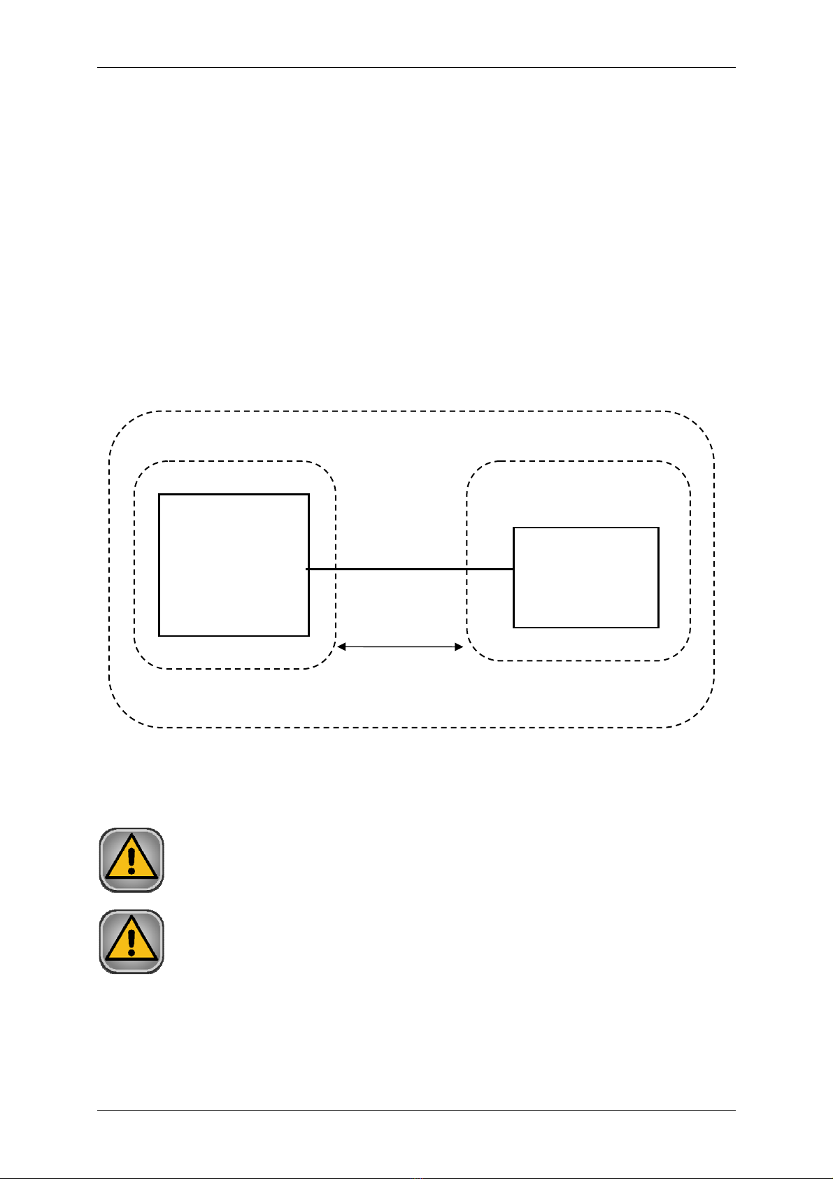
Fig. 4. Recommended arrangement of CRG 200 and PC.
In the patient’s environment only an Ergometer CRG 200 can be installed.
Devices which are not part of the system shall not be connected to it.
Patient’s environment
PC with AsTER /
CardioTEST
software
Ergometer
CRG 200
≥1,5 m
Facility for medical purposes

Operation manual Ergometer CRG 200 v.5xx IU-AT-77-C_I_ENG
ASPEL S.A. 19.05.2020 Strona 14 z 31
2.4. Functions
Ergometer enables load adjustment within the range of 25 – 1001 W. Rotation
measuring rate is 20 – 150 rpm. Ergometer is controlled by a PC computer through
RS-232 interface.
Load level is controlled by a microprocessor, therefore it does not depend on speed,
which in turn can be adjusted according to patient’s individual needs.
Ergometer is equipped with ECG mode recording 12 standard leads.
Together with Cardio TEST software, Ergometer CRG 200 is used to carry out
exercise tests.
Together with AsTER software, Ergometer CRG 200 it is intended for cardiologic
rehabilitation.
2.5. Main technical and operational parameters
Dimensions (LxWxG): 1030 x 580 x 1240 mm
Weight: 41 kg
Supply: External power supply CRG 200-M24 (integral part of
Ergometer CRG 200)
Supply voltage: 100 ÷240V AC; 47 ÷ 63 Hz
Max current consumption: 2A (for 100÷120V); 1A (for 220÷240V)
DC socker: 24V; 2A max
Braking: processor-controlled brake with torque measurement
(load does not depend on speed)
Communication interface: RS-232
Load level: 25 ÷ 1001 W,
Load accuracy ± 5 W to the power level 50W and ± 10 % above 50 W
Rotational speed: 20 ÷ 150 rpm ± 4 rpm
Max weight of the user: 201 kg
Operation modes:
○Continuous operation – average load max 100W
○Continuous operation with intermittent load- average
load max 200 W – working completion factor 66%
(2:1) (maximum working time 30 min; idle time 15
min.)
○Continuous operation with intermittent load- average
load max 200 W – working completion factor 40%
(2:3) (maximum working time 10 min; idle time 15
min.)
○Continuous operation with intermittent load- average
load max 200 W – working completion factor 40%
(1:4) (maximum working time 3 min; idle time 12 min.)

Operation manual Ergometer CRG 200 v.5xx IU-AT-77-C_I_ENG
ASPEL S.A. 19.05.2020 Strona 15 z 31
Safety of use: EN 60601-1
Electromagnetic compatibility: EN 60601-2
Medical device class: IIa (rule 10)
Type of anti-electric shock
protection (EN 60601-1): Class II
Classification of training equipment
(EN 957-1): Class SA
Equipment class and group
acc. to CISPR-11: Class A, group 1
IP protection class: IP X0
ECG signals: 12 standard leads (diagnostic mode),
2 leads (training mode)
Sensitivity: 2,5/5/10/20 mm/mV ± 5%
Recording speed: 25/50/100 mm/s ± 5%
Frequency range: 0,05 ÷ 150 Hz
HR measuring range: 15 - 240 bpm
HR measuring error: ± 2 %
HR resolution: 1 bpm
Digital filters: 25 Hz, 35 Hz, 50 Hz, anti-drift filter
Monitoring range of ST section: ± 3 mm (10mm/mV)
ST measuring error: ± 0,2 mm (10mm/mV)
ST resolution: 0,1 mm (10mm/mV)
Applied part (EN 60601-1): defibrillation-resistant type CF
Input circuit is secured against defibrillating impulse. After the impulse, the ECG line
will appear after no longer than 10 seconds.
2.6. Equipment
•AC/DC power supply CRG 200-M24.
•Power cable.
•Data cable.
•KEKG 51 v.103 patient cable (for an exercise test).
•KEKG 52 v.105 patient cable (for cardiological rehabilitation).
•Disposable ECG leads (50 pcs).
•Abrasive paste.
•Warranty card.
ECG parameters:

Operation manual Ergometer CRG 200 v.5xx IU-AT-77-C_I_ENG
ASPEL S.A. 19.05.2020 Strona 16 z 31
2.7. Manufacturer and designation
ASPEL S.A.
os. H. Sienkiewicza 33
PL 32-080 Zabierzów
tel. +48 12 285 22 22, fax +48 12 285 30 30
www.aspel.com.pl
Fig.5. Rating plate

Operation manual Ergometer CRG 200 v.5xx IU-AT-77-C_I_ENG
ASPEL S.A. 19.05.2020 Strona 17 z 31
3. Operation of Ergometer
Aspel S.A. offers training course on Ergometer CRG 200 operation.
3.1. Start-up of the device
Before first start-up after few days of using it is necessary to check mounting of
all connections.
Ergometer should be positioned on an even, stable ground and properly leveled (with
feet regulating knobs).
Before a training session height of the seat and position of handlebars should be
adjusted in the way of letting a person performing exercises feel comfortable. Power
supply should be connected to Ergometer's DC socket and power supply network.
Moving the seat's pillar post beyond marked regulation range is forbidden.
Electrical system of a room, where cyclometer is to be installed should fulfill IEC
requirements for electrical system safety.
Connect data cable to the Ergometer and to PC’s USB / RS-232 port.
Installation and start-up should be performed according to this description
(location of devices acc to fig. 4) and PC computer user manual (supplied with
computer set).
Only a PC computer with CE Declaration of Conformity (compliant with EN 60950)
can be connected to the USB / RS232 socket (by data cable).
Use the patient’s cable and the data cable supplied by the manufacturer.
Connect patient’s cable to ECG socket placed on Ergometer’s control board.

Operation manual Ergometer CRG 200 v.5xx IU-AT-77-C_I_ENG
ASPEL S.A. 19.05.2020 Strona 18 z 31
•When using the Ergometer, place the power supply, power cable and data
cable in such a way that they are not exposed to mechanical damage.
•After installing and starting the device, prepare an acceptance protocol
(signed by a person installing the device and the client) confirming that
the device has been appropriately installed and commissioned, according
to this manual and EN 60601-1 standard.
•Apart from the acceptance protocol, the client should be provided with
Operation Manual for the Ergometer CRG 200 and computer set and
relevant declarations of conformity.
•It is forbidden to conduct any modifications of location and composition
of the devices without prior written consent of the manufacturer.
•After any modification in terms of device composition, compliance with
EN 60601-1: section 16 standard should be verified again.
•Free space required for safe use of Ergometer should not be smaller than
0.6 m from the side with access to the device and must include the
landing area (free space can be shared if there is other training equipment
placed nearby).
•In order to get off from Ergometer safely you should stop pedaling and
while holding the handlebar go down on either right or left side of the
device.
Fig.6. Free space required for safe use
>0,6 m
>0,6 m

Operation manual Ergometer CRG 200 v.5xx IU-AT-77-C_I_ENG
ASPEL S.A. 19.05.2020 Strona 19 z 31
3.2. Patient preparation
After a cardiologist has established types of leads appropriate for a given patient it is
necessary to comply with the following guidelines for the examinations to be of high-
quality:
oAttach electrodes to the ossified area above the ribs or sternum in order to
reduce muscle interferences. When an electrode is placed over large muscle
areas or between the ribs a high-frequency artefact is formed that significantly
disturbs the signal. Placing an electrode over fatty areas also causes signal
disturbances.
oAll hair at the site of electrode placement should be removed during dry
shaving.
oThe electrode placement site needs to be carefully cleaned of dirt and fat from
the superficial epithelium. It should be done by rubbing the site with abrasion
cream (do not use spirit, use gauze not a compress due to better abrasive
properties.)
oThe middle of the site where a contact part of an electrode will be in contact
with the skin should be wiped with gauze with abrasive cream so as to remove
the superficial layer of dead epithelial cells (epithelial abrasion.) Before sticking
electrodes remove the remains of abrasive cream and exfoliated epithelial cells
with a gauze pad. As a result the electrical contact between the skin and
electrode surface will be better and a signal of high-quality will be obtained.
oElectrodes should be stuck in a way ensuring their good adhesion and so as not
to squeeze electrolyte gel from a sponge placed between the skin and the metal
part of the electrode.
oWhen connecting electrodes special attention should be paid so as the
conducting parts of electrodes and the patient cable would not touch each other
or other metal parts including protective grounding.
oWhen the electrodes are attached inappropriately the letters INOP are visible (in
a window of Ergometer controlling software.)

Operation manual Ergometer CRG 200 v.5xx IU-AT-77-C_I_ENG
ASPEL S.A. 19.05.2020 Strona 20 z 31
3.2.1. Electrode placement for an exercise test
Fig. 7. Electrode placement for an exercise test
Limb electrodes:
RA red right arm,
LA yellow left arm,
LL green left leg,
RL black right leg.
Precardiac electrodes:
V1 white-red fourth intercostal space on the right of the sternum,
V2 white-yellow fourth intercostal space at the left edge of the sternum,
V3 white-green in the mid-distance between V2 and V4,
V4 white-brown fifth intercostal space in the left midclavicular line,
V5 white-black along the straight line from V4 vertically to the left anterior
axillary line at the cross-section with this line,
V6 white-purple at the same level as V5 but in the left mid-axillary line.
Table of contents
Popular Exercise Bike manuals by other brands


Sunny Health & Fitness
Sunny Health & Fitness PERFORMANCE INTERACTIVE SF-B220030 user manual

Inspire
Inspire IC 1.5 Assembly & owners manual

Weslo
Weslo Pursuit2.2 Bike user manual

Pro-Form
Pro-Form CrossTrainer 56 user manual

FREE MOTION
FREE MOTION upright bike c7.7 user manual

Kettler
Kettler Speed 3 Assembly instruction


