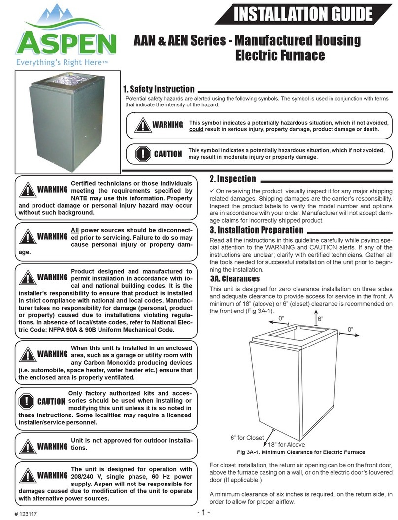
Aspen AEU Series User manual

1
`
INSTALLATION GUIDE
AEU & AED Series - Manufactured Housing
Electric Furnace Kit
1. Safety Instruction
!WARNING
Potential safety hazards are alerted using the following symbols. The symbol is used in conjunction with terms
that indicate the intensity of the hazard.
This symbol indicates a potentially hazardous situation, which if not avoided,
could result in serious injury, property damage, product damage or death.
This symbol indicates a potentially hazardous situation, which if not avoided,
may result in moderate injury or property damage.
CAUTION
!
Only factory authorized kits and acces-
sories should be used when installing or
modifying this unit unless it is so noted in
these instructions. Some localities may require a licensed
installer/service personnel.
CAUTION
!
Certied technicians or those individuals
meeting the requirements specied by
NATE may use this information. Property
and product damage or personal injury hazard may occur
without such background.
!WARNING
All power sources should be disconnect-
ed prior to servicing. Failure to do so may
cause personal injury or property dam-
age.
!WARNING
Product designed and manufactured to
permit installation in accordance with lo-
cal and national building codes. It is the
installer’s responsibility to ensure that product is installed
in strict compliance with national and local codes. Manufac-
turer takes no responsibility for damage (personal, product
or property) caused due to installations violating regula-
tions. In absence of local/state codes, refer to National Elec-
tric Code: NFPA 90A & 90B Uniform Mechanical Code.
!WARNING
When this unit is installed in an enclosed
area, such as a garage or utility room with
any Carbon Monoxide producing devices
(i.e. automobile, space heater, water heater etc.) ensure that
the enclosed area is properly ventilated.
!WARNING
The unit is designed for operation with
208/240 V, single phase, 60 Hz power
supply. Aspen will not be responsible for
damages caused due to modication of the unit to operate
with alternative power sources.
!WARNING
Unit is not approved for outdoor installa-
tions.
!WARNING
3. Installation Preparation
3A. Clearances
Read all the instructions in this guideline carefully while paying spe-
cial attention to the WARNING and CAUTION alerts. If any of the
instructions are unclear; clarify with certied technicians. Gather all
the tools needed for successful installation of the unit prior to begin-
ning the installation.
This unit is designed for zero clearance installation on three sides
and adequate clearance to provide access for service in the front. A
minimum of 18” (alcove) or 6” (closet) clearance is recommended on
the front end (Fig 3A-1).
For closet installation, the return air opening can be on the front door,
above the furnace casing on a wall, or on the electric door’s louvered
door (If applicable.)
A minimum clearance of six inches is required, on the return side, in
order to allow for proper airow.
Fig 3A-1. Minimum Clearance for Electric Furnace
2. Inspection
üOn receiving the product, visually inspect it for any major shipping
related damages. Shipping damages are the carrier’s responsibility.
Inspect the product labels to verify the model number and options
are in accordance with your order. Manufacturer will not accept dam-
age claims for incorrectly shipped product.
18” for Alcove
6” for Closet
0”
0” 6”

2
3B. Closet and Alcove Installation
These units are designed to be installed in a closet or an alcove.
If installing the electric furnace into a closet or an alcove, the unit
must leave front clearance to service the unit. The bottom of the unit
should also rest on a sturdy platform or oor.
Airow must be made available to the electric furnace’s return. Not
doing so may cause improper heating as well as premature heating
element failure.
Ensure that the unit is adequately sized.
The tonnage of the outdoor unit should
never exceed the tonnage of this unit.
CAUTION
!
Fig 3B. Closet Installation
Wall Mount
Return Air Grille
3B-1. AEU-000 Conguration
Mount electric furnace onto the coil cabinet (if shipped in downow
conguration, refer to section 4 for cabinet reconguration) and
secure with Alignment Plates on each side (see Figure 3B-1). See
section 5 for more information on easily aligning the single door onto
the nal assembly.
Figure 3B-1 (Filter Size: 18x20x1)
3B-2. AED-001 (Front Return Only) Conguration
Mount coil cabinet on top of electric furnace and secure both unit
with the Alignment Plates (Figure 3B-2). There are pre-holes on
coil cabinet but you will need to self-drill onto the electric furnace to
secure plates. Mount the Louver Single Door to nalize assembling.
See section 5 for more information on easily aligning the single door
onto the nal assembly. Unit is not eld-congurable into upow
orientation without separate solid door and convertible coil cabinet.
Figure 3B-2 (Filter Size: 18x20x1)
3B-3. AED-000 Downow (Top Return) &
AED-002 Downow (Top/Front):
Mount coil cabinet on top of electric furnace. Secure both units
with the Alignment Plates (Figure 3B-3). There are pre-holes on
coil cabinet but you will need to self-drill onto the electric furnace
to secure plates. Mount the louvered door to nalize assembling for
top/front return; for the AED-000, a separate solid door is required.
See section 5 for more information on easily aligning the single door
onto the nal assembly.
Figure 3B-3 (Filter Size: 18x20x1)

3
3B-4. AEU Coil Cabinet Reconguration
Step 1: On the electric furnace, self-drill Door Hook (Item D) on top
of the electric furnace. See Figure 3B-4A
Figure 3B-4A
Step 2: Conguring coil box, remove lter from top/front return con-
guration (Figure 3B-4B) and insert on bottom of the cabinet for lter-
ing return air (Figure 3B-4C).
Figure 3B-4B
Top/Front Return (Before)
Figure 3B-4C
Bottom Return (After)
Filter U-Retainer
design allows
lter to be easily
replaced when
needed.
Figure 3B-4D
Upow Re-Conguration
3B-5. Filter Care
The lter should be checked every month. You may replace the lter
by simply removing single door and sliding out the existing one to
replace with a new lter.
Figure 3B-5
Filter Size:
18x20x1
3B-6. Door Mounting
When installing the single door onto the nal assembly of AEU or
AED follow these steps:
• While standing in front of AEU or AED, insert bottom ange at an
angle into the unit. See Figure 3B-6A.
• Lift the top of the single door into the Door Hook / Top Bracket
(v-feature) at upright position to slowing slide down the door into
feature. See Figure 3B-6B.
Figure 3B-6A Figure 3B-6B
3B-7. Conversion Kits
MODEL CONFIGURATION
(DEFAULT)
RETURN
(DEFAULT)
DOOR
(DEFAULT) CONVERTIBLETO KITNEEDEDFORCONVERSION
AED‐000(DOWNFLOW/TOPRETURN) SEESECTION3B‐3PAGE2
AED‐001(DOWNFLOW/FRONTRETURN) AEDK‐01‐SEEFIGURE3B‐7A
AED‐002(DOWNFLOW/TOP&FRONTRETURN) AEDK‐02‐SEEFIGURE3B‐7B
AEU‐000(UPFLOW/BOTTOMRETURN) SEESECTION3B‐1PAGE2
AED‐001(DOWNFLOW/FRONTRETURN) AEDK‐01‐SEEFIGURE3B‐7C
AED‐002(DOWNFLOW/TOP&FRONTRETURN) AEDK‐02‐SEEFIGURE3B‐7D
AEU‐000(UPFLOW/BOTTOMRETURN) AEDK‐03‐SEEFIGURE3B‐7E
AED‐000(DOWNFLOW/TOPRETURN) AEDK‐03‐SEEFIGURE3B‐7F
AED‐002(DOWNFLOW/TOP&FRONTRETURN) AEDK‐04‐SEEFIGURE3B‐7G
AEU‐000(UPFLOW/BOTTOMRETURN) AEDK‐05‐SEEFIGURE3B‐7H
AED‐000(DOWNFLOW/TOPRETURN) AEDK‐06‐SEEFIGURE3B‐7J
AED‐001(DOWNFLOW/FRONTRETURN) AEDK‐07‐SEEFIGURE3B‐7K
AED‐001 DOWNFLOW FRONT LOUVERED
AED‐002 DOWNFLOW TOP&FRONT LOUVERED
AEU‐000 UPFLOW BOTTOM SOLID
AED‐000 DOWNFLOW TOP SOLID

4
3B-7A. KIT# - AEDK-01, AEU-000 TO AED-001 (DOWNFLOW/FRONT RETURN) CONVERSION
3B-7B. KIT# - AEDK-02, AEU-000 TO AED-002 (DOWNFLOW/TOP&FRONT RETURN) CONVERSION
ALIGNMENT
PLATES
(PART: 123190)
SCREW
123199
FILTER 18X20X1
(PART: 8767)
123211
DOOR HOOK
(PART: 123204)
(STEP #2)
SOLID SINGLE
DOOR
(PART: 123202)
(STEP #2)
FOAM STRIP-(PART: 8668)
CUT TO 31.10" (QTY: 2)
123196
(STEP #2)
123206
(STEP #2)
123197
(STEP#4)
LOUVER SINGLE
DOOR
(PART: 123203)
(STEP#8)
SCREW
ALIGNMENT
PLATES
(PART: 123190)
123211
123199
INSTRUCTIONS:
STEP#1 - REMOVE THE DOOR & ALIGNMENT PLATES (2). ROTATE THE AEN
& ENSURE THE BLOWER IS DIRECTING AIR DOWNWARD (180°)
STEP#2 - DISCARD THE PARTS# 123202, 123196, 123206 & 123204
STEP#3 - MOUNT THE FILTER BRACKET 2 ON EACH SIDE USING THE SCREWS
STEP#4 - MOUNT THE "TOP SOLID" 123197 ON TOP OF THE CABINET USING THE SCREWS
STEP#5 - MOUNT THE "BLOCK-OFF PLATE" 123216 AS SHOWN USING THE SCREWS 8051
STEP#6 - MOUNT THE MAD CABINET ON TOP OF THE AEN CABINET AND SECURE IT IN PLACE USING
THE ALIGNMENT PLATES AND SCREWS
STEP#7 - SLIDE IN THE FILTER INTO THE FILTER RETAINER
STEP#8 - MOUNT THE LOUVERED DOOR 123203 (REFER I/O FOR DOOR MOUNTING)
123216
(STEP#5)
8051
FILTER 18X20X1
(PART: 8767)
(STEP#7)
AED-001
123200 & 201
(STEP#3)
FOAM STRIP-(PART: 8668)
CUT TO 31.10" (QTY: 2)
# 138001
NOVEMBER 2022
KIT#: AEDK-01
AEU-000 TO AED-001 (DOWNFLOW/FRONT RETURN)
CONVERSION
AEU-000
MAD
AEN
MAD
AEN
INSTRUCTIONS:
STEP#1 - REMOVE THE ALIGNMENT PLATES (2). ROTATE AEN
TO ENSURE THE BLOWER IS DIRECTING AIR DOWNWARD (180°)
STEP#2 - DISCARD THE PARTS# 123202, 123196, 123206 & 123204
STEP#3 - MOUNT THE FILTER BRACKET 2 ON EACH SIDE USING THE SCREWS
STEP#4 - MOUNT THE "TOP SOLID" 123197 ON TOP OF THE CABINET USING THE SCREWS
STEP#5 - MOUNT THE "BLOCK-OFF PLATE" 123216 AS SHOWN USING THE SCREWS 8051
STEP#6 - MOUNT THE MAD CABINET ON TOP OF THE AEN CABINET AND SECURE IN PLACE USING
THE ALIGNMENT PLATES AND SCREWS
STEP#7 - SLIDE IN THE FILTER INTO THE FILTER RETAINER
STEP#8 - MOUNT THE LOUVERED DOOR 123203 (REFER I/O FOR DOOR MOUNTING)
PARTS NEEDED FOR CONVERSION
ITEM #
PART #
DESCRIPTION
Qty.
1 123203
LOUVER SINGLE DOOR, AED
1
2 123197
CABINET TOP SOLID, MHAH 24-60
1
3 123200
FILTER RETAINER, LEFT 24IN H
1
4 123201
FILTER RETAINER, RIGHT 24IN H
1
5 123216
BLOCK-OFF PLATE (MAD)
1
6 8051
# 10 X 1/2 TEK SCREW - AIR HANDLERS
2
Figure 3B-7A
ALIGNMENT
PLATES
(PART: 123190)
SCREW
123210
FILTER 18X20X1
(PART: 8767)
123211
DOOR HOOK
(PART: 123204)
(STEP#2)
SOLID SINGLE
DOOR
(PART: 123202)
(STEP#2)
123206
(STEP#3)
123212
LOUVER SINGLE
DOOR
(PART: 123203)
(STEP#7)
SCREW
ALIGNMENT
PLATES
(PART: 123190)
123211
FILTER 18X20X1
(PART: 8767)
(STEP#6)
.
123206
(STEP#3)
123200 & 201
(STEP#4)
# 138002
NOVEMBER 2022
KIT#: AEDK-02
AEU-000 TO AED-002 (DOWNFLOW/TOP&FRONT RETURN)
CONVERSION
INSTRUCTIONS:
STEP#1 - REMOVE THE ALIGNMENT PLATES (2). ROTATE THE AEN
& ENSURE THE BLOWER IS DIRECTING AIR DOWNWARD (180°)
STEP#2 - DISCARD THE PARTS# 123202, 8668 & 123204
STEP#3 - REMOVE THE PART#123206 FROM THE BOTTOM OF THE CABINET AND SLIDE IT AT THE TOP OF THE
CABINET AND SECURE IN POSITION USING THE SCREWS
STEP#4 - MOUNT THE FILTER BRACKET 123200 & 201 ON EACH SIDE OF THE MAD CABINET USING THE SCREWS
STEP#5- MOUNT THE MAD CABINET ON TOP OF THE AEN CABINET AND SECURE IT IN PLACE USING
THE ALIGNMENT PLATES AND SCREWS
STEP#6 - SLIDE IN THE FILTERS INTO THE FILTER RETAINERS
STEP#7 - MOUNT THE LOUVERED DOOR 123203 (REFER I/O FOR DOOR MOUNTING)
AED-002
AEU-000
AEN
MAD
MAD
AEN
# 123086
NOVEMBER -2022
PARTS NEEDED FOR CONVERSION
ITEM #
PART #
DESCRIPTION
Qty.
1 123203
LOUVER SINGLE DOOR, AED
1
2 8767
FILTER- 18X20X1
1
3 123200
FILTER RETAINER, LEFT 24IN H
1
4 123201
FILTER RETAINER, RIGHT 24IN H
1
5 8506
#10X1/2 SLTD SCREW
2
Figure 3B-7B

5
3B-7C. KIT# - AEDK-01, AED-000 TO AED-001 (DOWNFLOW/FRONT RETURN) CONVERSION
3B-7D. KIT# - AEDK-02, AED-000 TO AED-002 (DOWNFLOW/TOP&FRONT RETURN)CONVERSION
ALIGNMENT
PLATES
(PART: 123190)
SCREW
123210
FILTER 18X20X1
(PART: 8767)
(STEP#8)
123211
DOOR HOOK
(PART: 123204)
(STEP#5)
SOLID SINGLE
DOOR
(PART: 123202)
(STEP#9)
FOAM STRIP-(PART: 8668)
CUT TO 31.10" (QTY: 2)
(STEP#6)
123206
(STEP#3)
123206
(STEP#4)
123197
(STEP#4)
LOUVER SINGLE DOOR
(PART: 123203)
(STEP#8)
SCREW
ALIGNMENT
PLATES
(PART: 123190)
123211
123209
INSTRUCTIONS:
STEP#1 - REMOVE THE ALIGNMENT PLATES (2) AND BRING THE MAD CABINET DOWN.
STEP#2 - DISCARD THE PARTS# 123203, 123197, 123200, 123201 & 123216
STEP#3 - SLIDE IN THE PART# 123206 AT THE TOP OF THE CABINET AND SECURE IN POSITION USING THE SCREWS
STEP#4 - MOUNT THE TOP BRACKET PART#123196 ON THE MAD CABINET AND SECURE IN POSITION USING THE SCREWS
STEP#5 - MOUNT THE DOOR HOOK PART#123204 & SELF-DRILL ONTO AEN. ------ CHECK-----
STEP#6 - MOUNT THE MAD CABINET ON TOP OF THE AEN CABINET AND SECURE IT IN PLACE USING
THE ALIGNMENT PLATES AND SCREWS
STEP#7 - SLIDE IN THE FILTER INTO THE FILTER RETAINER AT THE TOP
STEP#8- MOUNT THE SOLID DOOR 123202 (REFER I/O FOR DOOR MOUNTING)
STEP#9 - DISCARD PART# 8668
123200 &123201
(STEP#2)
123216
(STEP#5)
# 138001
NOVEMBER 2022
123210
123211
SOLID SINGLE
DOOR
(PART: 123202)
(STEP#1)
FILTER 18X20X1
(PART: 8767)
SCREW
DOOR HOOK
123204
(STEP#5)
ALIGNMENT
PLATES
(PART: 123190)
123196
(STEP#2)
123206
(STEP#2)
KIT#: AEDK-01
AED-000 TO AED-001 (DOWNFLOW/FRONT RETURN)
CONVERSION
AED-000 AED-001
AEN
MAD
MAD
AEN
INSTRUCTIONS:
STEP#1 - REMOVE THE DOOR & ALIGNMENT PLATES (2). ROTATE THE AEN
& ENSURE THE BLOWER IS DIRECTING AIR DOWNWARD (180°)
STEP#2 - DISCARD THE PARTS# 123202, 123196, 123206 & 123204
STEP#3 - MOUNT THE FILTER BRACKET 2 ON EACH SIDE USING THE SCREWS
STEP#4 - MOUNT THE "TOP SOLID" 123197 ON TOP OF THE CABINET USING THE SCREWS
STEP#5 - MOUNT THE "BLOCK-OFF PLATE" 123216 AS SHOWN USING THE SCREWS 8051
STEP#6 - MOUNT THE MAD CABINET ON TOP OF THE AEN CABINET AND SECURE IT IN PLACE USING
THE ALIGNMENT PLATES AND SCREWS
STEP#7 - SLIDE IN THE FILTER INTO THE FILTER RETAINER
STEP#8 - MOUNT THE LOUVERED DOOR 123203 (REFER I/O FOR DOOR MOUNTING)
# 123081
NOVEMBER -2022
PARTS NEEDED FOR CONVERSION
ITEM #
PART #
DESCRIPTION
Qty.
1 123202
SOLID SINGLE DOOR, AEU
1
2 123206
FILTER U-RETAINER ASSY
1
3 123196
TOP BRACKET, MHAH 24-60
1
3 123204
DOOR HOOK
1
4 8668
CLOSED CELL FOAM
1
PARTS NEEDED FOR CONVERSION
ITEM #
PART #
DESCRIPTION
Qty.
1 123203
LOUVER SINGLE DOOR, AED
1
2 123197
CABINET TOP SOLID, MHAH 24-60
1
3 123200
FILTER RETAINER, LEFT 24IN H
1
4 123201
FILTER RETAINER, RIGHT 24IN H
1
5 123216
BLOCK-OFF PLATE (MAD)
1
6 8051
# 10 X 1/2 TEK SCREW - AIR HANDLERS
2
Figure 3B-7C
ALIGNMENT
PLATES
(PART: 123190)
SCREW
123210
FILTER 18X20X1
(PART: 8767)
123211
DOOR HOOK
(PART: 123204)
(STEP#2)
SOLID SINGLE
DOOR
(PART: 123202)
(STEP#2)
FOAM STRIP-(PART: 8668)
CUT TO 31.10" (QTY: 2)
(STEP#2)
123206
(STEP#3)
123212
LOUVER SINGLE
DOOR
(PART: 123203)
(STEP#5)
SCREW
ALIGNMENT
PLATES
(PART: 123190)
123211
FILTER 18X20X1
(PART: 8767)
(STEP#4)
.
123200 & 201
(STEP#3)
123210
123211
SOLID SINGLE
DOOR
(PART: 123202)
(STEP#1)
FILTER 18X20X1
(PART: 8767)
SCREW
DOOR HOOK
123204
(STEP#5)
ALIGNMENT
PLATES
(PART: 123190)
MAD
AEN
KIT#: AEDK-02
AED-000 TO AED-002 (DOWNFLOW/TOP&FRONT RETURN)
CONVERSION
INSTRUCTIONS:
STEP#1 - REMOVE THE DOOR PART#123202 FROM THE UNIT
STEP#2 - DISCARD THE PARTS# 123202, & 123204
STEP#3 - MOUNT THE FILTER BRACKET 123200 & 201 ON EACH SIDE OF THE MAD CABINET USING THE SCREWS
STEP#4 - SLIDE IN THE FILTERS INTO THE FILTER RETAINERS
STEP#5 - MOUNT THE LOUVERED DOOR 123203 (REFER I/O FOR DOOR MOUNTING)
AED-002AED-000
AEN
MAD
MAD
AEN
# 123086
NOVEMBER -2022
# 138002
NOVEMBER 2022
PARTS NEEDED FOR CONVERSION
ITEM #
PART #
DESCRIPTION
Qty.
1 123203
LOUVER SINGLE DOOR, AED
1
2 8767
FILTER- 18X20X1
1
3 123200
FILTER RETAINER, LEFT 24IN H
1
4 123201
FILTER RETAINER, RIGHT 24IN H
1
5 8506
#10X1/2 SLTD SCREW
2
Figure 3B-7D

6
3B-7E. KIT# - AEDK-03, AED-001 TO AEU-000 (UPFLOW/BOTTOM RETURN) CONVERSION
3B-7F. KIT# - AEDK-03, AED-001 TO AED-000 (DOWNFLOW/TOP RETURN) CONVERSION
ALIGNMENT
PLATES
(PART: 123190)
SCREW
123210
FILTER 18X20X1
(PART: 8767)
(STEP#7)
123211
DOOR HOOK
(PART: 123204)
(STEP#5)
SOLID SINGLE
DOOR
(PART: 123202)
(STEP#8)
123206
(STEP#3)
123206
(STEP#4)
123197
(STEP#2)
LOUVER SINGLE DOOR
(PART: 123203)
(STEP#2)
SCREW
ALIGNMENT
PLATES
(PART: 123190)
123211
123209
INSTRUCTIONS:
STEP#1 - REMOVE THE ALIGNMENT PLATES (2). ROTATE THE AEN & ENSURE THE BLOWER IS DIRECTING AIR UPWARD (180°).
FIRST NEED TO SELF-DRILL THE DOOR HOOK ONTO AEN MODEL BEFORE MOUNTING IT ON TOP OF MAD MODEL.
STEP#2 - DISCARD THE PARTS# 123203, 123197, 123200, 123201 & 123216
STEP#3 - SLIDE IN THE PART# 123206 AT THE BOTTOM OF THE CABINET AND SECURE IN POSITION USING THE SCREWS
STEP#4 - MOUNT THE TOP BRACKET PART#123196 ON THE MAD CABINET AND SECURE IN POSITION USING THE SCREWS
STEP#5 - MOUNT THE DOOR HOOK PART#123204 & SELF-DRILL ONTO AEN.
STEP#6 - MOUNT THE AEN CABINET ON TOP OF THE MAD CABINET AND SECURE IT IN PLACE USING
THE ALIGNMENT PLATES AND SCREWS
STEP#7 - SLIDE IN THE FILTER INTO THE FILTER RETAINER AT THE BOTTOM
STEP#8 - MOUNT THE SOLID DOOR 123202 (REFER I/O FOR DOOR MOUNTING)
123200 &123201
(STEP#2)
123216
(STEP#2)
KIT#: AEDK-03
AED-001 TO AEU-000 (UPFLOW/BOTTOM RETURN)
CONVERSION
AEU-000
AED-001
AEN
MAD
MAD
AEN
# 123087
NOVEMBER -2022
# 138003
NOVEMBER 2022
PARTS NEEDED FOR CONVERSION
ITEM #
PART #
DESCRIPTION
Qty.
1 123202
SOLID SINGLE DOOR, AEU
1
2 123206
FILTER U-RETAINER ASSY
1
3 123196
TOP BRACKET, MHAH 24-60
1
4 123204
DOOR HOOK
1
PARTS NEEDED FOR CONVERSION
ITEM #
PART #
DESCRIPTION
Qty.
1 123202
SOLID SINGLE DOOR, AEU
1
2 123206
FILTER U-RETAINER ASSY
1
3 123196
TOP BRACKET, MHAH 24-60
1
3 123204
DOOR HOOK
1
4 8668
CLOSED CELL FOAM
1
Figure 3B-7E
ALIGNMENT
PLATES
(PART: 123190)
SCREW
123210
FILTER 18X20X1
(PART: 8767)
(STEP#8)
123211
DOOR HOOK
(PART: 123204)
(STEP#5)
SOLID SINGLE
DOOR
(PART: 123202)
(STEP#9)
FOAM STRIP-(PART: 8668)
CUT TO 31.10" (QTY: 2)
(STEP#6)
123206
(STEP#3)
123206
(STEP#4)
123197
(STEP#2)
LOUVER SINGLE DOOR
(PART: 123203)
(STEP#2)
SCREW
ALIGNMENT
PLATES
(PART: 123190)
123211
123209
INSTRUCTIONS:
STEP#1 - REMOVE THE ALIGNMENT PLATES (2) AND BRING THE MAD CABINET DOWN.
STEP#2 - DISCARD THE PARTS# 123203, 123197, 123200, 123201 & 123216
STEP#3 - SLIDE IN THE PART# 123206 AT THE TOP OF THE CABINET AND SECURE IN POSITION USING THE SCREWS
STEP#4 - MOUNT THE TOP BRACKET PART#123196 ON THE MAD CABINET AND SECURE IN POSITION USING THE SCREWS
STEP#5 - MOUNT THE DOOR HOOK PART#123204 & SELF-DRILL ONTO AEN.
STEP#6 - MOUNT THE MAD CABINET ON TOP OF THE AEN CABINET AND SECURE IT IN PLACE USING
THE ALIGNMENT PLATES AND SCREWS
STEP#7 - SLIDE IN THE FILTER INTO THE FILTER RETAINER AT THE TOP
STEP#8- MOUNT THE SOLID DOOR 123202 (REFER I/O FOR DOOR MOUNTING)
123200 &123201
(STEP#2)
123216
(STEP#2)
123210
123211
SOLID SINGLE
DOOR
(PART: 123202)
(STEP#8)
FILTER 18X20X1
(PART: 8767)
(STEP#7)
SCREW
DOOR HOOK
123204
(STEP#5)
ALIGNMENT
PLATES
(PART: 123190)
123196
(STEP#4)
123206
(STEP#3)
# 138003
NOVEMBER 2022
KIT#: AEDK-03
AED-001 TO AED-000 (DOWNFLOW/TOP RETURN) CONVERSION
AED-000AED-001
AEN
MAD
MAD
AEN
# 123087
NOVEMBER -2022
PARTS NEEDED FOR CONVERSION
ITEM #
PART #
DESCRIPTION
Qty.
1 123202
SOLID SINGLE DOOR, AEU
1
2 123206
FILTER U-RETAINER ASSY
1
3 123196
TOP BRACKET, MHAH 24-60
1
4 123204
DOOR HOOK
1
PARTS NEEDED FOR CONVERSION
ITEM #
PART #
DESCRIPTION
Qty.
1 123202
SOLID SINGLE DOOR, AEU
1
2 123206
FILTER U-RETAINER ASSY
1
3 123196
TOP BRACKET, MHAH 24-60
1
3 123204
DOOR HOOK
1
4 8668
CLOSED CELL FOAM
1
Figure 3B-7F

7
3B-7G. KIT# - AEDK-04, AED-001 TO AED-002 (DOWNFLOW/TOP&FRONT RETURN) CONVERSION
3B-7H. KIT# - AEDK-05, AED-002 TO AEU-000 (UPFLOW/BOTTOM RETURN) CONVERSION
123216
(STEP#2)
LOUVER SINGLE
DOOR
(PART: 123203)
(STEP#1)
SCREW
ALIGNMENT
PLATES
(PART: 123190)
123211
123209
INSTRUCTIONS:
STEP#1 - REMOVE THE DOOR 123203 & FILTER 8767 AND SET ASIDE
STEP#2 - DISCARD THE PARTS# 123216 & 123197
STEP#3 - SLIDE IN THE PART# 123206 AT THE BOTTOM OF THE CABINET AND SECURE IN POSITION USING THE SCREWS
STEP#4 - MOUNT THE TOP BRACKET PART#123196 ON THE MAD CABINET AND SECURE IN POSITION USING THE SCREWS
STEP#5 - SLIDE IN THE FILTERS INTO THE FILTER RETAINERS AT THE TOP & FRONT
STEP#6 - MOUNT THE SOLID DOOR 123202 (REFER I/O FOR DOOR MOUNTING)
123197
(STEP#2)
123212
LOUVER SINGLE
DOOR
(PART: 123203)
(STEP#6)
SCREW
ALIGNMENT
PLATES
(PART: 123190)
123211
FILTER 18X20X1
(PART: 8767)
(STEP#5)
.
123206
(STEP#3)
123196
(STEP#4)
KIT#: AEDK-04
AED-001 TO AED-002 (DOWNFLOW/TOP&FRONT RETURN)
CONVERSION
AED-002AED-001
MAD
AEN
AEN
MAD
INSTRUCTIONS:
STEP#1 - REMOVE THE ALIGNMENT PLATES (2). ROTATE AEN TO ENSURE THE BLOWER IS DIRECTING AIR UPWARD (180°).
FIRST NEED TO SELF-DRILL THE DOOR HOOK ONTO AEN MODEL BEFORE MOUNTING IT ON TOP OF MAD MODEL.
STEP#2 - DISCARD THE PARTS# 123203, 123197, 123200, 123201 & 123216
STEP#3 - SLIDE IN THE PART# 123206 AT THE BOTTOM OF THE CABINET AND SECURE IN POSITION USING THE SCREWS
STEP#4 - MOUNT THE TOP BRACKET PART#123196 ON THE MAD CABINET AND SECURE IN POSITION USING THE SCREWS
STEP#5 - MOUNT THE DOOR HOOK PART#123204 & SELF-DRILL ONTO AEN.
STEP#6 - APPLY FOAM STRIP PART #8668 AT THE FRONT FACE OF THE AEN CABINET
STEP#7 - MOUNT THE AEN CABINET ON TOP OF THE MAD CABINET AND SECURE IT IN PLACE USING
THE ALIGNMENT PLATES AND SCREWS
STEP#8 - SLIDE IN THE FILTER INTO THE FILTER RETAINER AT THE BOTTOM
STEP#9 - MOUNT THE SOLID DOOR 123202 (REFER I/O FOR DOOR MOUNTING)
STEP#10 - DISCARD PART# 8668 FOR AED-001 TO AED-000 CONVERSION
# 123088
NOVEMBER -2022
# 138004
NOVEMBER 2022
PARTS NEEDED FOR CONVERSION
ITEM #
PART #
DESCRIPTION
Qty.
1 123206
FILTER U-RETAINER ASSY
1
2 123196
TOP BRACKET, MHAH 24-60
1
3 8506
#10X1/2 SLTD SCREW
4
4 8767
FILTER- 18X20X1
1
Figure 3B-7G
ALIGNMENT
PLATES
(PART: 123190)
SCREW
123210
FILTER 18X20X1
(PART: 8767)
(STEP#6)
123211
DOOR HOOK
(PART: 123204)
(STEP#4)
SOLID SINGLE
DOOR
(PART: 123202)
(STEP#7)
123206
(STEP#3)
123212
LOUVER SINGLE
DOOR
(PART: 123203)
(STEP#2)
SCREW
ALIGNMENT
PLATES
(PART: 123190)
123211
FILTER 18X20X1
(PART: 8767)
123206
(STEP#3)
123200 & 201
(STEP#2)
KIT#: AEDK-05
AED-002 TO AEU-000 (UPFLOW/BOTTOM RETURN)
CONVERSION
INSTRUCTIONS:
STEP#1 - REMOVE THE ALIGNMENT PLATES (2). ROTATE AEN AND
ENSURE THE BLOWER IS DIRECTING AIR UPWARD (180°)
STEP#2 - DISCARD THE PARTS# 123203, 8767(1), 123200 & 123201
STEP#3 - REMOVE THE PART#123206 FROM THE TOP OF THE CABINET AND SLIDE IT AT THE BOTTOM OF THE
CABINET AND SECURE IT IN POSITION USING THE SCREWS
STEP#4 - MOUNT THE DOOR HOOK PART#123204 & SELF-DRILL ONTO AEN.
STEP#5- MOUNT THE AEN CABINET ON TOP OF THE MAD CABINET AND SECURE IT IN PLACE USING
THE ALIGNMENT PLATES AND SCREWS
STEP#6 - SLIDE IN THE FILTER INTO THE FILTER RETAINER AT THE BOTTOM
STEP#7 - MOUNT THE SOLID DOOR 123202 (REFER I/O FOR DOOR MOUNTING)
AED-002 AED-000
AEN
MAD
MAD
AEN
# 123089
NOVEMBER -2022
# 138005
NOVEMBER 2022
PARTS NEEDED FOR CONVERSION
ITEM #
PART #
DESCRIPTION
Qty.
1 123202
SOLID SINGLE DOOR, AED
1
2 123204
DOOR HOOK
1
Figure 3B-7H

8
3B-7J. KIT# - AEDK-06, AEU-002 TO AED-000 (DOWNFLOW/TOP RETURN) CONVERSION
3B-7K. KIT# - AEDK-07, AED-002 TO AED-001 (DOWNFLOW/FRONT RETURN) CONVERSION
ALIGNMENT
PLATES
(PART: 123190)
SCREW
123210
FILTER 18X20X1
(PART: 8767)
123211
DOOR HOOK
(PART: 123204)
(STEP#2)
SOLID SINGLE
DOOR
(PART: 123202)
(STEP#2)
FOAM STRIP-(PART: 8668)
CUT TO 31.10" (QTY: 2)
(STEP#2)
123206
(STEP#3)
123212
LOUVER SINGLE
DOOR
(PART: 123203)
(STEP#1&2)
SCREW
ALIGNMENT
PLATES
(PART: 123190)
123211
FILTER 18X20X1
(PART: 8767)
.
123200 & 201
(STEP#2)
123210
123211
SOLID SINGLE
DOOR
(PART: 123202)
(STEP#4)
FILTER 18X20X1
(PART: 8767)
(STEP#3)
SCREW
DOOR HOOK
123204
(STEP#5)
ALIGNMENT
PLATES
(PART: 123190)
MAD
AEN
KIT#: AEDK-06
AEU-002 TO AED-000 (DOWNFLOW/TOP RETURN) CONVERSION
INSTRUCTIONS:
STEP#1 - REMOVE THE DOOR PART#123202 FROM THE UNIT
STEP#2 - DISCARD THE PARTS# 123203, 8767(1),123216, 123200 & 123201
STEP#3 - SLIDE IN THE FILTER INTO THE FILTER RETAINER AT THE TOP
STEP#4 - MOUNT THE SOLID DOOR 123202 (REFER I/O FOR DOOR MOUNTING)
AED-000AED-002
AEN
MAD
MAD
AEN
# 123091
NOVEMBER -2022
# 138006
NOVEMBER 2022
PART NEEDED FOR CONVERSION
ITEM #
PART #
DESCRIPTION
Qty.
1 123202
SOLID SINGLE DOOR, AED
1
Figure 3B-7J
123216
(STEP#2)
LOUVER SINGLE
DOOR
(PART: 123203)
(STEP#1)
SCREW
ALIGNMENT
PLATES
(PART: 123190)
123211
123209
INSTRUCTIONS:
STEP#1 - REMOVE THE DOOR 123203 & FILTER 8767
STEP#2 - DISCARD THE PARTS# 123206 & 123196
STEP#4 - MOUNT THE TOP BRACKET PART#123197 ON THE MAD CABINET AND SECURE IN POSITION USING THE SCREWS
STEP#5 - MOUNT THE "BLOCK-OFF PLATE" 123216 AS SHOWN USING THE SCREWS 8051
STEP#6 - SLIDE IN THE FILTERS INTO THE FILTER RETAINERS AT THE TOP & FRONT
STEP#7 - MOUNT THE LOUVERED DOOR 123203 (REFER I/O FOR DOOR MOUNTING)
123197
(STEP#2)
123212
LOUVER SINGLE
DOOR
(PART: 123203)
(STEP#6)
SCREW
ALIGNMENT
PLATES
(PART: 123190)
123211
FILTER 18X20X1
(PART: 8767)
(STEP#5)
.
123206
(STEP#3)
123196
(STEP#4)
KIT#: AEDK-07
AED-002 TO AED-001 (DOWNFLOW/FRONT RETURN) CONVERSION
AED-001AED-002
MAD
AEN
AEN
MAD
INSTRUCTIONS:
STEP#1 - REMOVE THE ALIGNMENT PLATES (2). ROTATE AEN TO ENSURE THE BLOWER IS DIRECTING AIR UPWARD (180°).
FIRST NEED TO SELF-DRILL THE DOOR HOOK ONTO AEN MODEL BEFORE MOUNTING IT ON TOP OF MAD MODEL.
STEP#2 - DISCARD THE PARTS# 123203, 123197, 123200, 123201 & 123216
STEP#3 - SLIDE IN THE PART# 123206 AT THE BOTTOM OF THE CABINET AND SECURE IN POSITION USING THE SCREWS
STEP#4 - MOUNT THE TOP BRACKET PART#123196 ON THE MAD CABINET AND SECURE IN POSITION USING THE SCREWS
STEP#5 - MOUNT THE DOOR HOOK PART#123204 & SELF-DRILL ONTO AEN.
STEP#6 - APPLY FOAM STRIP PART #8668 AT THE FRONT FACE OF THE AEN CABINET
STEP#7 - MOUNT THE AEN CABINET ON TOP OF THE MAD CABINET AND SECURE IT IN PLACE USING
THE ALIGNMENT PLATES AND SCREWS
STEP#8 - SLIDE IN THE FILTER INTO THE FILTER RETAINER AT THE BOTTOM
STEP#9 - MOUNT THE SOLID DOOR 123202 (REFER I/O FOR DOOR MOUNTING)
STEP#10 - DISCARD PART# 8668 FOR AED-001 TO AED-000 CONVERSION
# 123092
NOVEMBER -2022
# 138007
NOVEMBER 2022
PARTS NEEDED FOR CONVERSION
ITEM #
PART #
DESCRIPTION
Qty.
1 123197
CABINET TOP SOLID, MHAH 24-60
1
2 123216
BLOCK-OFF PLATE (MAD)
1
3 8051
# 10 X 1/2 TEK SCREW - AIR HANDLERS
2
Figure 3B-7K

9
Line voltage wiring should be
routed through the access holes
at the top of the electric fur-
nace. Proper electrical conduit
connection ttings should be
used. Connect the power wiring
to the line side connections on
the electric furnace. The electri-
cal ground wire should be con-
nected to the grounding lug.
Ensure both the eld supplied
ground wire and electric furnace
GREEN ground wire are both
secured to the grounding lug of
the electric furnace.
If the line voltage being sup-
plied to the electric furnace is
208 volt single phase, the line
voltage tap on the low voltage
transformer needs to be moved
from the 240 volt tap to the 208
volt tap. If this is not done, the
secondary output voltage of the
transformer will be too low.
208VAC
Tap
240VAC
Tap
5A. Single Stage Cooling with Electric Heat
5. Low Voltage Connections
The electric furnace comes factory setup for a single stage cool-
ing system. If factory installed accessory electric heaters are prein-
stalled, the unit will also have a low voltage wire for the electric heat
(Fig 5A-1).
Fig 5A-1.
4. Electrical Line Voltage Wiring
These units are designed for single or three phase 208/240 volts, 60
HZ power supply. Wire selection and wiring must be in accordance
with the National Electric Code and/or local codes. Unit terminals are
designed to accommodate copper and aluminum wiring. If aluminum
wiring is used: please observe special precautions relative to sizing,
wire connections and corrosion protection.
All models with 5,8 or 10 kW electric heat are arranged for single
circuit connections. Models larger than 10 kW are arranged for multi-
circuit protection. Refer to top part of wiring diagram at the end of this
guide for detailed information.
- Insulate between the oor base and the oor when used on a com-
bustible oor. Be sure to cut the insulation around the perimeter of
the duct connector opening.
- Install the oor base over the oor opening with the anges on the
11 x 13 inch opening facing down.
- Use four screws to secure the oor base to the oor.
It is recommended that wherever supply and return air sheet metal
ducts pass through unconditioned areas, they be insulated to pre-
vent excessive heat loss during heating operation. When applied in
conjunction with summer air conditioning, sheet metal duct routed
through unconditioned areas should be insulated and have an out-
side vapor barrier to prevent formation of condensation.
3C. Ductwork and Duct Connector
Duct systems should be installed in accordance with standards for
air-conditioning systems, National Fire Protection Association Pam-
phlet No. 90A or 90B. They should be sized in accordance with Na-
tional Environmental System Contractors Association Manual K, or
whichever is applicable. It is recommended that installers refer to
the “Manufactured Housing Duct System Guide to Best Practices”
by MHI-MHRA.
On any job, non-ammable exible collars should be used for the
return air and discharge connections to prevent transmission of vi-
bration. Although these units have been specially designed for quiet,
vibration-free operation, air ducts can act as soundboards if poorly
installed.
All main supply and return air drops should be properly sized as
determined by the designer of the duct system and should not nec-
essarily be the size of the duct ange openings of the unit. (The duct
size should never be smaller than the ange openings of the electric
furnace supply and return air openings.)
To install the duct connector:
- Attach duct connector foam gasket along the perimeter of the duct
opening to seal the duct connector to the top of the duct.
- To connect the duct connector, insert it into the oor opening and
bend back the tabs inside the duct. Fold the tabs over 90 degrees to
ensure a secure connection. Seal around the duct connector.
- Slit the corners of the duct connector that stick up above the oor,
and then bend the sides over onto the oor surface.

10
During cooling mode operation, the indoor blower G wire will ener-
gize a time delay relay inside the electric furnace. After a short time
delay period, the time delay relay contacts will close and apply power
to the blower motor. Fan delay periods are 7 seconds ON delay and
65 seconds OFF delay. (See Schematic)
The Y wire from the thermostat is not connected at the electric fur-
nace. This wire goes directly to the outdoor unit 24 volt wiring to turn
on the outdoor condensing unit when a call for cooling takes place.
The 24 volt common for the outdoor unit circuits is connected at the
electric furnace Brown wire.
The electric heater low voltage wiring W terminal is wired directly
from the thermostat to the electric furnace. The blower will delay a
heat call ON for a period of 5 seconds. The OFF delay period is 60
seconds.
Fig 5A-2.
Table 6-1.
Air volume needs to be set to the level recommended by the outdoor
unit equipment manufacturer. Most systems will require around 400
CFM of indoor air for every 1 ton of system cooling capacity. The air
volume must be set prior to attempting system charge.
This electric furnace uses a 240V PSC motor. The air volume level
produced by the electric furnaces at varying external static pressure
levels is shown in Table 6-1.
6. Air Volume Adjustment
Use a Magnehelic Gauge with a 1” scale and two static pressure
tips to measure the static pressure during the air volume adjustment
procedure. The high port static pressure tip should be placed in the
supply duct near the outlet of the electric furnace. The low port static
pressure tip should be placed in the return air duct near the entrance
to the electric furnace. The factory provided air lter should be in
place inside of the electric furnace.
1. Select a starting speed tap from the CFM table.
2. Call for fan only operation at the thermostat.
3. Read the external static pressure level on the Magnehelic gauge.
4. Make speed tap selection changes to get the air volume as close
as possible to the required level.
5. If the static pressure is above .5” wc , excessive turbulence or duct
friction needs to be reduced. (Obstructions in the duct system can
also cause excessive static pressure.)
6. When proper air volume is established, move on to the charging
procedure.
MODEL SPEED
TAP
MOTOR
HP
MOTOR
AMPS
MOTOR
VOLTAGE
CFM V. EXTERNAL STATIC*
0.10 0.20 0.30 0.40 0.50
AE(U/D)
T1
3/4 5.4 240
940 850 795 740 640
T2 1155 1070 1015 950 885
T3 1375 1305 1255 1180 1127
T4 1500 1430 1375 1315 1260
T5 1850 1800 1760 1710 1650
1. Bring airow up to the maximum CFM possible according to Table
6-1.
2. Evacuate refrigeration system to micron level required by outdoor
unit manufacturer.
3. Release system charge from outdoor unit and call for cooling.
4. Use outdoor unit equipment manufacturer specic charging charts
if available and make proper charge adjustment based upon outdoor
unit instructions.
5. If outdoor unit instructions and charts are not available, use Aspen
provided charts. Make certain indoor air temperature is near comfort
level setpoint 75F, prior to establishing superheat and subcooling
levels.
7. System Charging
An improperly charged system may cause degradation in sys-
tem performance and damage the compressor. After installation
of the coil, refer to the outdoor unit manufac-
turer for charging techniques and amount of
charge. If outdoor unit manufacturers charg-
ing instructions are unavailable; then refer to instructions below
to charge the system.
CAUTION
!
After all connections are made, start-up and checkout must be per-
formed before proper evaluation of the entire system can be made.
Make sure that heat anticipator is properly set as noted on thermo-
stat instructions. Load requirements can vary in each residence and
it may be necessary for the installer or homeowner to make slight ad-
justments to the heat anticipator setting for longer or shorter cycles.
It is recommended to change the setting no more than plus or minus
0.05 amps at a time. Greater changes can cause the unit to rapid
cycle or remain on excessively. Measure anticipator circuit current
with electric heaters energized and set anticipator to proper level.
8. Adjustment Of Heat Anticipator
9. Final System Checkout
1. Make certain all cabinet openings are properly sealed and any
grommets moved during installation are moved into proper place.
2. With cooling system operating, check for condensate leakage.
3. Perform leak detection inspection of refrigerant circuit and con-
necting piping.
4. Secure all cabinet doors

11
10. Wiring diagram for AEU/AED models
HIGH VOLTAGE disconnect all power sources prior to servicing. Failure might lead to safety hazard

373 Atascocita Rd.
Humble, TX 77396
Phone: 281.441.6500
Toll Free: 800.423.9007
Fax: 281.441.6510
www.aspenmfg.com
© Copyright 2022 Aspen Manufacturing. All Rights Reserved
# 123227
Revised 12-06-22. Subject to change without notice and without incurring obligation.
This manual suits for next models
5
Table of contents
Other Aspen Furnace manuals
Popular Furnace manuals by other brands

Carrier
Carrier 58DH Operating and maintaining

Bard
Bard WG3S2-A installation instructions

York
York P4UCB30N12206 Installation instruction

Bryant
Bryant CONDENSING GAS FURNACE 352MAV Installation, start-up, and operating instructions

VERDER
VERDER CARBOLITE GERO CFM 14/1 Installation, operation and maintenance instructions

VERDER
VERDER CARBOLITE GERO RWF 12/23 Installation, operation and maintenance instructions