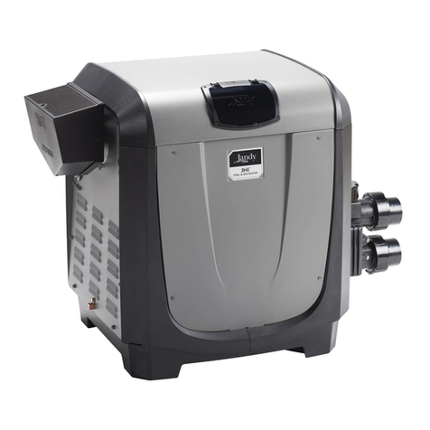
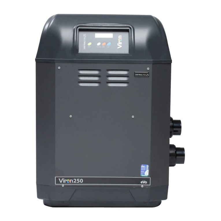
Astral Pool ICI Series User manual

ICI
Gas pool heater
INST 471
INSTALLATION MANUAL
FOR YOUR SAFETY - This product must be installed and serviced by a licensed electrician in accordance with
AS/NZ 3000 and any other local applicable regulations. Before installing this product, read and follow all warning
notices and instructions that accompany this product. Failure to follow warning notices and instructions may
result in property damage, personal injury, or death. Improper installation and/or operation will void the warranty.
Improper installation and/or operation can create unwanted electrical hazard which can cause serious injury,
property damage, or death.
WARNING
(all models)

3
ICI gas pool heater Installation Manual
2
ICI gas pool heater Installation Manual
EQUIPMENT INFORMATION RECORD
DATE OF INSTALLATION
INSTALLER INFORMATION
INITIAL PRESSURE GAUGE READING
WITH CLEAN FILTER
PUMP MODEL
HORSEPOWER
FILTER MODEL
CONTROL PANEL MODEL
SERIAL NUMBER

3
ICI gas pool heater Installation Manual
2
ICI gas pool heater Installation Manual
Table of Contents
Section 1. Important Safety Instructions ...........4
Section 2. General Information.............................. 6
2.1 Technical Assistance................................................................6
2.2 Warranty ......................................................................................6
2.3 Consumer Information and Safety.....................................6
2.4 General Operation Description...........................................6
2.5 Specifications.............................................................................7
2.6 Dimensions.................................................................................7
2.7 Certification Codes and Standards ....................................8
Section 3. Getting Started ....................................... 8
3.1 Contents ......................................................................................8
3.2 Required Equipment...............................................................9
Section 4. Location Requirements......................10
4.1 Clearances................................................................................ 10
4.2 Outdoor Installation............................................................. 10
4.3 Indoor Installation................................................................. 10
Section 5. Gas Connections ..................................14
5.1 Supply Gas Requirements.................................................. 14
5.2 Inlet Gas Pressure Test ......................................................... 14
5.3 Special Precautions for LP Gas.......................................... 14
5.4 Gas Pipe Sizing Tables.......................................................... 15
5.5 Check Burner Performance................................................ 15
Section 6. Water Connections..............................16
6.1 Pump Sizing ............................................................................ 16
6.2 Plumbing Connections ....................................................... 16
6.3 Water Pressure Switch Adjustment................................. 17
6.4 Check Valve Installation ...................................................... 17
6.5 Pressure Relief Valve Installation ..................................... 17
6.6 Condensate Drain ................................................................. 18
Section 7. Electrical Connections........................19
7.1 Electronic Flow Response................................................... 19
Section 8. Final Installation Check......................21
8.1 Important Safety Information........................................... 21
8.2 What To Do If You Smell Gas.............................................. 21
8.3 First Time Start-up Procedure ........................................... 21
8.4 Lighting Instructions............................................................ 21
8.5 To Turn Off Gas To Heater................................................... 21
8.6 Shutting Down the Heater................................................. 21
Section 9. Operation................................................22
9.1 Normal Operation................................................................. 22
9.2 Digital Thermostat Operation........................................... 22
9.3 ICI User Controls .................................................................... 22
Section 10. Maintenance..........................................24
10.1 Water Chemistry.................................................................... 24
10.2 Winterizing .............................................................................. 24
10.3 Corrosion Prevention In Heaters...................................... 24
10.4 Maintenance Schedule........................................................ 25
10.5 Service Notification .............................................................. 25
Section 11. Troubleshooting...................................27
11.1 Display Symbol Indicators.................................................. 27
Section 12. Spare Parts..............................................28
12.1 Model ICI 200.......................................................................... 28
12.2 Model ICI 200 Spare Parts List........................................... 29
12.3 Model ICI 400.......................................................................... 30
12.4 Model ICI 400 Spare Parts List........................................... 31

5
ICI gas pool heater Installation Manual
4
ICI gas pool heater Installation Manual
Section 1. Important Safety Instructions
READ AND FOLLOW ALL INSTRUCTIONS
All electrical work must be performed by a licensed electrician and conform to all national, state, and local
codes. When installing and using this electrical equipment, basic safety precautions should always be followed,
including the following:
WARNING
Prolonged immersion in hot water may induce hyperthermia. Hyperthermia occurs when the internal temperature of
the body reaches a level several degrees above the normal body temperature of 37°C. The symptoms of hyperthermia
include dizziness, fainting, drowsiness, lethargy, and an increase in the internal temperature of the body. The effects of
hyperthermia include: 1) unawareness of impending danger; 2) failure to perceive heat; 3) failure to recognize the need to
exit spa; 4) physical inability to exit spa; 5) fetal damage in pregnant women; 6) unconsciousness resulting in a danger of
drowning.
DANGER
To reduce the risk of severe injury or death, do not remove the suction fittings of your spa or hot tub. Never operate a spa
or hot tub if the suction fittings are broken or missing. Never replace a suction fitting with one rated less than the flow rate
marked on the equipment assembly.
WARNING
To Reduce the Risk of Injury -
a) The water in a spa should never exceed 40°C. Water temperatures should remain between 38°C and 40°C. The water in
a spa should never exceed 40°C. Water temperatures between 38°C and 40°C are considered safe for a healthy adult.
Lower water temperatures are recommended for young children and when spa use exceeds 10 minutes.
b) Since excessive water temperatures have a high potential for causing fetal damage during the early months of
pregnancy, pregnant or possibly pregnant women should limit spa water temperatures to 38°C. Before entering a spa
or hot tub, the user should measure the water temperature with an accurate thermometer since the tolerance of water
temperature-regulating devices varies.
d) The use of alcohol, drugs, or medication before or during spa or hot tub use may lead to unconsciousness with the
possibility of drowning.
e) Obese persons and persons with a history of heart disease, low or high blood pressure, circulatory system problems,
or diabetes should consult a physician before using a spa.
f) Persons using medication should consult a physician before using a spa or hot tub since some medication may induce
drowsiness while other medication may affect heart rate, blood pressure, and circulation.
WARNING
Risk of electric shock - Install the controller at least 3.5 metres from the inside wall of the pool and/or hot tub using non-
metallic plumbing.
Children should not use spas or hot tubs without adult supervision.
Do not use spas or hot tubs unless all suction guards are installed to prevent body and hair entrapment.
People using medications and/or having an adverse medical history should consult a physician before using a spa or hot
tub.
WARNING
To avoid injury ensure that you use this control system to control only packaged pool/spa heaters which have built-in
operating and high limit controls to limit water temperature for pool/spa applications. This device should not be relied
upon as a safety limit control.

5
ICI gas pool heater Installation Manual
4
ICI gas pool heater Installation Manual
WARNING
To minimize possibility of fire or electric shock, which could result in property damage, and/or serious injury, including loss
of life, power to the Viron Connect should be supplied by an isolating switch or through a residual current device (RCD)
with a rated residual operating current not exceeding 30mA.
SAVE THESE INSTRUCTIONS
WARNING
People with infectious diseases should not use a spa or hot tub.
To avoid injury, exercise care when entering or exiting the spa or hot tub.
Do not use drugs or alcohol before or during the use of a spa or hot tub to avoid unconsciousness and possible drowning.
Before entering a spa or hot tub, measure the water temperature with an accurate thermometer.
Do not use a spa or hot tub immediately following strenuous exercise.
Prolonged immersion in a spa or hot tub may be injurious to your health.
Do not permit any electric appliance (such as a light, telephone, radio, or television) within 3.5 metres of a spa or hot tub.
The use of alcohol, drugs or medication can greatly increase the risk of fatal hyperthermia in hot tubs and spas.
Water temperature in excess of 38°C may be hazardous to your health.
Attention Installer: Install to provide drainage of compartment for electrical
components.
WARNING
A terminal bar marked "GROUND" is provided within the controller. To reduce the risk of electrical shock which can cause
serious injury or death, connect this terminal bar to the grounding terminal of your electric service or supply panel with a
continuous copper conductor having green insulation and one that is equivalent in size to the circuit conductors supplying
this equipment in accordance with AS/NZ 3000. In addition, where required, bonding should be extended in accordance
with AS/NZ 3000 to any metal ladders, water pipes, or other metal within 3.5 m of the pool/spa.

7
ici gas pool heater Installation Manual
6
ici gas pool heater Installation Manual
Section 2. General Information
This manual provides installation and operation
instructions for the AstralPool ICI pool and spa gas
heater.
Read the installation and operation instructions
completely before proceeding with the
installation.
2.1 Technical Assistance
Web: www.astralpool.com.au Phone: 1300 186 875
2.2 Warranty
This heater is sold with a limited factory warranty.
Details are included with this heater. For warranty
terms and conditions, please visit:
www.astralpool.com.au.
All warranty issues should be resolved with your
AstralPool dealer or place of purchase. Claims must
include the heater serial number and model (this
information can be found on the rating plate),
installation date, and name of the installer. Shipping
costs are not included in the warranty coverage.
The warranty does NOT cover damage caused by
improper assembly, installation, operation or field
modification. Also, any damage to the heat exchanger
caused by improper water chemistry will NOT be
covered by the warranty.
NOTE: Keep this manual in a safe place for future
reference when inspecting or servicing the heater.
2.3 Consumer Information and Safety
The heater is designed and manufactured to provide
many years of safe and reliable service when
installed, operated, and maintained according to the
information in this manual and the installation codes
referred to throughout. Be sure to read and comply
with all warnings and cautions.
WARNING
Improper installation or maintenance can cause
nausea or asphyxiation from carbon monoxide in ue
gases which could result in severe injury, or death. For
indoor installations, as an additional measure of safety,
AstralPool strongly recommends the installation of
suitable Carbon Monoxide detectors in the vicinity of
this appliance and in any adjacent occupied spaces.
WARNING
The following “Safety Rules for Hot Tubs,”
recommended by the U.S. Consumer Product Safety
Commission, should be observed when using the spa.
Consult heater operation and installation instructions
for water temperature guidelines before setting
temperature.
• Spa or hot tub water temperature should never
exceed 40°C (104°F). 38°C (100°F) is considered safe for
a healthy adult. Special caution is recommended for
young children.
• The drinking of alcoholic beverages before or
during spa or hot tub use can cause drowsiness which
could lead to unconsciousness, and subsequently
result in drowning.
• Pregnant women take note! Soaking in water
above 38.5°C (102°F) can cause fetal damage during
the rst three (3) months of pregnancy (which could
result in the birth of a brain-damaged or deformed
child). If pregnant women are going to use a spa or
hot tub, they should make sure the water temperature
is below 38°C (100°F) maximum.
• The water temperature should always be checked
with an accurate thermometer before entering a spa
or hot tub. Temperature controls may vary by as much
as 1C°/1F°.
• Persons with a medical history of heart disease,
diabetes, circulatory or blood pressure problems
should consult their physician before using a hot tub
or spa.
• Persons taking any medication which induces
drowsiness (e.g., tranquilizers, antihistamines, or anti-
coagulants) should not use spas or hot tubs.
• Prolonged immersion in hot water can induce
hyperthermia.
• Hyperthermia occurs when the internal body
temperature reaches a level several degrees above the
normal body temperature of 37°C (98.6°F). Symptoms
include dizziness, fainting, drowsiness, lethargy, and
an increase in the internal body temperature. The ef-
fects of hyperthermia include:
• Lack of awareness of impending hazard
• Failure to perceive heat
• Failure to recognize need to leave spa
• Physical inability to leave spa
• Fetal damage in pregnant women
• Unconsciousness resulting in a danger of
drowning
2.4 General Operation Description
The ICI GAS POOL HEATER can safely be connected to
PVC pipe. It accepts high water flow rates which help
the heater run cooler, giving greater efficiency and
long life. In addition, it is equipped with electronic
start up and an accurate electronic thermostat to
ensure ease of use and accurate temperature control.
The electronic display tells at a glance the operational
status of the heater.
The ICI GAS POOL HEATER requires a minimum of 120
litres per minute flow for the ICI 200 and 200 litres
per minute for the ICI 400 models. The maximum
permissible flow rate is 500 litres per minute. For flow
rates in excess of 500 litres per minute, an external by-
pass valve must be fitted.
7
ici gas pool heater Installation Manual
6
ici gas pool heater Installation Manual
2.5 Specifications
Model ICI 200 ICI 400
Gas Inlet Rate 215 MJ/hr 400 MJ/hr
Gas Connection AS/NZ 5601 AS/NZ 5601
Gas Usage Rate of
Nominal Rate
(must be within %)
+/- 5 +/- 5
NG Inlet Static Gas
Pressure (kPa)
1.13 - 5 1.13 - 5
LPG Inlet Static Gas
Pressure (kPa)
2.75 - 5 2.75 - 5
NG Gas Inlet
Operating Pressure-
High Fire (kPa)
1.13 1.13
LPG Gas Inlet
Operating Pressure-
High Fire (kPa)
2.75 2.75
Water Flow Rate 120 - 500 200 - 500
Water pH 7.6 - 7.8 7.6 - 7.8
Water Total Alkalinity
(ppm)
80 -120 80 -120
Water Calcium
Hardness (ppm)
150 - 350 150 - 350
Water Salinity (ppm) 5000 maximum 5000 maximum
Chlorine Maximum
Content (ppm)
3 3
Bromine Maximum
Content (ppm)
5 5
Air-Free NG - CO
Level (ppm)
30 - 60 30 - 60
Air-Free LPG - CO
Level (ppm)
50 - 150 50 - 150
2.6 Dimensions
Figure 1. Front Dimensions
Figure 2. Side Dimensions
Figure 3. Header Height

9
ici gas pool heater Installation Manual
8
ici gas pool heater Installation Manual
2.7 Certification Codes and Standards
Certied IAPMO R&T Oceana
COMPLIANT Standard for ‘Gas Pool Heaters’, AS 4560
Applicable National
Installation and Com-
missioning code(s)
Standard for Gas Installations, AS/NZS
5601
Pay particular attention to the chapter ad-
dressing Venting of Equipment
All AstralPool Gas heaters must be installed in accordance with the local
building and installation codes as per the utility or Authority Having
Jurisdiction (AHJ). In the absence of local codes, please refer to the latest
edition of the national codes for installation:
The ICI pool and spa heaters meet or exceed the requirements of energy
conservation regulations such as those in regions that have disallowed
the use of continuously lit pilot type ignition sources.
Section 3. Getting Started
Install the ICI in accordance with the procedures in this
manual, local codes and ordinances, and in
accordance with the latest edition of the appropriate
national code. See Section Section 4.
If the heater is to be operated in below freezing
conditions it should be installed in a protected
outdoor shelter. See Section 4.3.
All gas-fired products require correct installation to
ensure safe operation. The requirements for pool
heaters include the following:
• Field assembly (if required)
• Appropriate site location, clearances and ooring see
Section Section 4.
• Sucient combustion and ventilation air
• Properly sized gas meter and piping
• Proper electrical wiring
• Sucient water ow
This manual provides the information needed to meet
these requirements. Review all applications and
installation procedures before continuing the
installation.
3.1 Contents
Before starting, check that you have the correct parts as
indicated in Table 1. If any parts are missing or incorrect,
please call your local distributor or technical support at
1300 186 875 for assistance.
1
23
4
Figure 4. ICI Gas Heater Contents

9
ici gas pool heater Installation Manual
8
ici gas pool heater Installation Manual
Item Description Quantity
1 ICI Gas Heater 1
2 50mm Universal Union Nut 2
3 50mm Universal Union Tail 2
4 50mm Universal Union O-ring 2
Table 1. ICI Gas Heater Parts
3.2 Required Equipment
Please ensure that the following equipment is
available to the installer at the time of installation.
3.2.1 Required Tools
Safety Eye Wear Gloves Philips
Screwdriver
Flathead
Screwdriver
Pipe Wrench Adjustable
Wrench
5mm (3/16”)
Hex Key
Multi Grips Digital Dierential
Manometer
Voltage Meter PVC Pipe Cutter
Tape Measure
Power Drill
Figure 5. Required Tools
3.2.2 Materials Supplied by Installer
Please ensure that all materials used during the
installation are in accordance with local codes or the
authority having jurisdiction (AHJ) requirements. If
you have any questions regarding the materials that
need to be used during this installation please call the
AstralPool customer service center at 1300 186 875.
Indoor installations will require additional venting and
exhaust conversion materials which are outlined in
detail in Section Section 4.
NOTE: Required materials may dier from the materials
listed. Be sure to conrm with all local and national
codes before beginning the installation.
Gas Supplies Electrical
Supplies
Plumbing
Supplies
Appropriately sized
Gas Piping
230 VAC, 50 Hz PVC Piping
Manual Gas Shut Off
Valve
PVC Cement
Gas Union Te on Tape
Cap Red RTV 300° C (600°F)
rated silicone adhesive
Leak Solution
1.6 mm (1/16")
Hose “T”
3.18 mm (1/8") -
1.6 mm (1/16")
Barbed Adapter
1.6 mm (1/16")
Flexible Hose

11
ici gas pool heater Installation Manual
10
ici gas pool heater Installation Manual
Section 4. Location Requirements
WARNING
Improper installation or maintenance can cause nausea or
asphyxiation from carbon monoxide in ue gases which
could result in severe injury or death. For indoor instal-
lations, as an added measure of safety, Zodiac strongly
recommends installation of suitable
carbon monoxide detectors in the vicinity of this appli-
ance and in any adjacent occupied spaces.
Incorrect design and installation of heater vents and
ducts can result in personal injury, damage to property, or
death. To avoid such hazards, the heater must be installed
only by a qualied professional service technician.
The ICI heater is shipped from the factory with an
exhaust vent configured for outdoor installation. The
heater is designed and certified, per AS 4560 for both
outdoor and indoor installation in Australia and for
indoor and outdoor installation of natural gas only
heaters in New Zealand. It is shipped from the factory
configured for outdoor use only, and is intended for
use with permanently installed, swimming pools only.
It should be installed on a level, stationary, non-mobile
location and should not be subjected to intentional
movement, vibration, etc. which could negatively
affect the plumbing, wiring, and venting of the heater.
For installation indoors, be sure to follow all the
instructions provided in this instruction manual. See
Section 4.3 for details.
Location of the heater below or above the pool water
level affects operation of its water pressure switch. See
Section 6.3 for more information.
NOTE: If the heater is to be operated in below
freezing conditions it should be installed in a
protected outdoor shelter.
CAUTION
When pool equipment is located below the pool surface,
a leak from any component can cause large scale water
loss or ooding. AstralPool cannot be responsible for
such water loss or ooding or resulting damage.
4.1 Clearances
Installation clearances must comply with AS/NZ 5601.
The heater is approved for installation at reduced
clearances as below.
Outdoor
Clearances From
Combustible
Surfaces
Non-
combustible
Surfaces
Front 300mm 300mm
Both Sides 300mm 300mm
Rear 300mm 50mm
Above 1000mm 1000mm
Indoor
Clearances From
Combustible
Surfaces
Non-
combustible
Surfaces
Front 300mm 300mm
Both Sides 300mm 50mm
Rear 300mm 50mm
Above 500mm 500mm
4.2 Outdoor Installation
Locate the heater:
• On a level solid surface.
• 3.5 m (12’) from inner pool edge unless separated by a
permanent solid barrier, i.e. a wall or fence.
• In an open area, not under a deck or other structure.
• Away from doors windows or louvres that connect in
any way to occupied or inhabited areas of the building.
• Away from rainwater runo.
• Away from potential sprinkler water intrusion.
• So that the top of the heater is at least 1 m (3’) below
any overhang.
• So that the top surface of the heater is at least 1 m (3’)
above any forced air inlet within 3 m (10’).
WARNING
Do not install the heater with the top of the vent
assembly within 1.22 m (4') horizontally, 1.22 m (4’)
below or less than 300 mm (1') above any opening into a
building. Local codes and installation requirements may
vary.
4.3 Indoor Installation
AstralPool does not encourage installation of LP
(liquid propane) gas heaters indoors. Always consult
with the authority having jurisdiction (AHJ) along with
all applicable national and local codes before
installing a LP heater indoors. Please be sure to refer to
Section 5.3.
The heater is Certified by IAPMO-R&T Oceana for
indoor installations. Please keep in mind the
clearances from Section 4.1 when selecting an
installation location. You will also need to make
considerations for ventilation, see Section 4.3.1. In
addition, when pool equipment is installed indoors,
appropriate containment measures and drains should
be considered for the prevention of property damage
in the event of an equipment leak.
NOTE: An outdoor shelter is an unoccupied enclosure
which does not communicate directly with occupied
areas.
AstralPool does not recommend outdoor shelter
installations that depend on internal air for combustion.
4.3.1 Ventilation
When installing the heater indoors, it is imperative
that an adequate supply of fresh air is provided for
combustion. Failure to provide adequate ventilation
voids all warranties and may be a danger to persons or
property.

11
ici gas pool heater Installation Manual
10
ici gas pool heater Installation Manual
Two permanent openings shall be provided directly to
outside. The openings shall be located to ensure the
distance between the top of the upper opening and
the ceiling of the room or enclosure, and the distance
between the bottom of the lower opening and the
floor of the room or enclosure does not exceed 5% of
the height of the room or enclosure.
The minimum vertical dimension of any free
ventilation opening shall be 6 mm.
The minimum free ventilation area provided directly
outside by each opening shall be:
Model Area
ICI 200 57,000 mm2
ICI 400 87,000 mm2
If ventilation provided is obtained from an adjacent
room then these areas will increase.
The following diagram is provided as a guide only. All
fluing and installation work must be carried out by
an authorized person. Fluing must conform to local
regulations and to A.G.A. installation code
AS/NZ 5601. Care must be taken to provide the
correct ventilation and correct fluing materials in close
proximity to combustible surfaces.
Approved Gas
Termination Cowl
600
1500
Upper Grille For
Fresh Air
Ventilation
Lower Grille For
Fresh Air
Ventilation
Figure 6. Ventilation Guideline Example
Figure 7. Location Requirements
min. 3.5 m (12’)min. 3.5 m (12')
unless the heater is separated
from the pool by a solid fence, wall
or other permanent solid barrier.
Locate the heater on a level surface in an open, unroofed
area at least 1.0 m (3
'
) from gas meter, 500 mm (1.5
'
)
from an electrical meter or fuse box (prohibited area
extends to the ground below meter or fuse box), and 150
mm (6
"
) from any drain pipe or soil pipe. Keep the area
surrounding the heater free from mulch, pine needles and
other flammable material.
Do not install the heater under a deck.
The heater must be installed on a level, solid, and firm surface or platform. This
heater is not intended for any mobile installations. Although it is always preferable to
install the heater on a non-combustible surface, the ICI gas heater has been certified
by IAPMO-R&T Oceana to applicable national standards for installation on solid, firm,
and level combustible surfaces. DO NOT INSTALL ON CARPET.
Do not locate the
heater below or adjacent
to any doors, windows,
louvres, grills, etc., which
connect in any way with
an inhabited area of a
building, even though
the access might be
through another struc-
ture (e.g., a garage or
utility room).
If the heater is installed close to a structure, protect it from rain
water runoff with rain gutters on the roof or other measures.
Be sure to divert rain water runoff away from heater
The area under an
overhang must be
open on three sides to
prevent combustion
gases from being
diverted into living
areas through doors,
windows, or gravity
inlets
Install the heater so that there is at least 500 mm (1.5
'
) of
clearance between the bottom of the overhang to the top of the
heater exhaust vent.
Install the heater so that the top of the vent is at least 1.5 m (5')
from any building opening including windows, doors, air inlets
including pool spa blowers or any other opening into the
building with the exception of sub-floor ventilation.
The top surface of the heater must be at least 1.0 m (3') above any
forced air inlet, or intake ducts located within 3.0 m (10') horizontally.
Required exhaust
distance:
•500 mm (1.5')
from any return
wall, building
surface or
external corner.
•150 mm (6")
from all other
combustible
surfaces.
Do not locate the heater near sprinkler
systems that could spray water on it.
Water from sprinklers can damage
controls and electronic components.
CAUTION
WARNING

13
ici gas pool heater Installation Manual
12
ici gas pool heater Installation Manual
WARNING
Do not install spa blowers in the same room as a gas
heater. This is potentially dangerous to spa users.
WARNING
Do not store chemicals or fuel in the same room
as the gas heater. This may cause fire or explosion.
When installing in a garage the ICI GAS POOL
HEATER must be installed 450 mm above floor level.
4.3.2 Indoor Exhaust Conversion
For indoor installations an outdoor unit must be
converted by an authorized person. The appliance will
be labelled as an indoor model on completion
The Indoor Flue kit for indoor units must be purchased
through AstralPool and can be run up to 16m in length
with a maximum of 3 x 90 degree bends.
The Indoor Flue kit for all ICI model heaters is part
number 78270
Figure 8. Indoor Flue Kit Contents
Extra lengths of Flue pipe (1 mtr long) can be
purchased separately.
Bends (90 & 45 degree) can also be purchased
separately, 78227 – 90degree, 78228 – 45 degree
Heater must be installed to AS/NZ 5601 standard.
Access and suitable working areas must be available
to the heater ref to page 11 of this manual for
minimum required clearances.
Flue pipe is supplied in 1 metre lengths and can be
easily assembled with one end reduced in diameter
so they slip together. It is advisable that each join be
screwed or riveted together upon final assembly.
The flue pipe can be cut shorter when required with
the use of a hacksaw or tin snips by cutting from the
non-reduced end of the flue pipe.
The Flue temperature can reach 200 Celsius (392
farenheit) and should be kept at least 25 mm clear of
any combustible surface.
Rooftop terminations.
All flue exiting the roof must be shielded with the gal
cover. Extra lengths of gal can be supplied. Decktite
fittings / flashings must be attached to the galvanised
flue cover. Brace flue in high wind applications.
Locate flue cowl onto reduced end of the flue pipe.
Attach with rivets / screws to hold into place
Wall terminations.
Wall penetration kit (Part No 78287) can be purchased
from Astralpool. See photo below
Figure 9. Wall Penetration Kit
Ensure location is suitable as flue gases exit all around
cowl and may blow back onto walls, eaves, features
causing discoloration or mould and moisture issues.
Condensation will occur around the flue exit area and
condensation may drip from the flue outlet.
All flues exiting the wall must be shielded with the gal
cover. Extra lengths of gal can be supplied. Decktite
fittings / flashings / wall exiting covers must be
attached to the galvanized flue cover.
For long extensions of flue exiting the wall bracing
may be required in high wind applications.
Locate flue cowl onto reduced end of the gal outer
covering / flue pipe. Attach with rivets / screws to hold
into place. Ensure a drain hole in the cowl is facing
down.

13
ici gas pool heater Installation Manual
12
ici gas pool heater Installation Manual
The flue pipe must slope slightly towards the cowl
for the last horizontal run (approx 2ºC deg) to allow
condensation to drain.
Figure 10. Wall Penetration Kit Installation
To convert an ICI heater from Outdoor to Indoor
configuration, follow the steps below.
1. Remove the 4 x retaining screws (retain the 4 screws to
reuse to retain the Indoor ue top) for from the Flue
top and lift o the top cover.
Figure 11. Remover Retaining Screws
2. Once the outdoor ue top cover is removed, you
will nd already tted to the heater a spigot that the
stainless steel ue 1 meter will neatly slip over.
Figure 12. Spigot Location For Flue Installation
3. Slip the rst section of the Stainless steel ue over
the spigot
Figure 13. Install Flue into Spigot
4. Once the rst section is tted to the heater you can
now t the Indoor Flue top by sliding it over the ue
tube. Locate correctly onto the heater and reuse
the 4 screws from the outdoor ue top to retain the
Indoor ue top to the heater.
Figure 14. Indoor Flue Top Installation
5. Continue the installation of the reminder of the Flue
ducting. It is advisable that each join be screwed/
riveted together to ensure the ue ducting stays
together and doesn’t come apart during operation of
the heater .

15
ici gas pool heater Installation Manual
14
ici gas pool heater Installation Manual
Section 5. Gas Connections
The gas connection is on the right hand side of the
heater. A 22mm M.I. connection is provided for gas
line connection. An approved manual shut off valve
must be installed in the gas fitting line before the
heater.
The gas fitting line should be installed by an
authorised person and comply with local regulations
and Australian Standard code AS/NZ 5601. The gas
line from the meter will usually be of a larger size than
the gas inlet connection.
The heater gas valve has a built in pressure regulator
and 1/8” pressure test point. On starting the heater,
a manometer must be used and the supply inlet
pressure checked while the heater is running against
the heater data plate. Incorrect inlet pressures may
void warranty and may result in service charges,
should service be required. Gas valves are preset
and should only be adjusted by trained AstralPool
technicians.
5.1 Supply Gas Requirements
• Refer to AS/NZS 5601.1 for correct gas inlet piping
length from the gas meter to the heater.
• Conrm correct supply pipe size and supply pressure
before proceeding with the installation.
• Check the gas meter to make sure it will supply enough
gas to the heater and any other appliances using the
same gas supply. If unsure, contact your local gas utility
to conrm.
• It is critical that the incoming gas supply pressure at the
heater is within the maximum and minimum pressure
requirements as outlined in Section 5.2. If the range
of acceptable supply pressure is not provided, the gas
supply system to the heater must be modied to meet
pressure requirements.
• Consider pipe ttings when determining gas pipe
sizing. For every elbow used add 900 mm (3) to
straight pipe length.
• Install a manual gas shuto valve outside the heater
body for service and safety. Never install the shuto
valve inside the body of the heater.
• Where required by local code, install a sediment trap/
condensate fall and gas union in accordance with
Australia standard 5601. See Figure 15.
• Do not use a restrictive gas cock.
ATTENTION
Do not use flexible appliance connectors on any gas
connections unless the connector is AGA approved
for outdoor installation, and is marked with the BTUH
capacity (which must be equal to or greater than the
heater rated input) and the type of gas (Natural or
LP). Also, any flexible connectors, such as CSST buried
underground must be certified for underground
installation and meet all applicable codes. Please note,
use of flexible connector still requires the installation of a
sediment trap. See Figure 15.
PIPE
NIPPLE
SEDIMENT TRAP
Image is for reference of a trap/fall
assembly, the specifics and location
of your trap/fall assembly may differ.
Please ensure that your installation
complies with local authorities and
Australian standard 5601.
Figure 15. Manual Shut-off Valve and Sediment Trap
NOTE: The gas line from the meter is usually larger
than the gas valve. Therefore, you will need to reduce
connecting pipe as necessary. Make this reduction as
close to the heater as possible.
5.2 Inlet Gas Pressure Test
1. Note – gas pressure must be measured when unit is
operating.
2. Set thermostat to “OFF”.
3. Remove top cover
4. Loosen screw from ” brass test point located on inlet
side of gas valve
5. Connect manometer tube to test point
6. Set thermostat to “ON” and wait for burner to ignite
7. Once burner has ignited, the manometer must
indicate the nominal inlet pressure listed below.
8. Adjust inline pressure to meet minimum required
pressure at main gas regulator. Do not adjust gas valve
settings..
9. Tighten test point screw.
10. Ret covers.
Required Inlet Static gas pressure (ie: when heater not
operating)
Natural Gas 1.13 kPa minimum 5 kPa maximum
Propane 2.75 kPa minimum 5 kPa maximum
5.3 Special Precautions for LP Gas
This appliance is approved for use with LP (Propane)
and Natural Gas in Australia only. It is approved for use
with Natural gas only in New Zealand. Under the same
environmental conditions, liquid propane (LP) gas is
more dense or heavier than air and will more readily
collect or pool in enclosed areas if adequate
ventilation is not provided. It is not recommended to
install LP gas heaters in enclosed areas such as pits.
Locate heaters a safe distance from LP gas cylinders
and filling equipment. Consult the Australian / New
Zealand Standard AS/NZS 1596 and gas installation

15
ici gas pool heater Installation Manual
14
ici gas pool heater Installation Manual
standard AS/NZS 5601, and any other local codes and
fire protection authorities about specific installation
restrictions in your area.
For ALL installations the combustion air openings
requirements and AS/NZS 5601 MUST be followed
for safe and proper operation.
5.4 Gas Pipe Sizing Tables
Note: Gas pipe sizing tables are indicative only. All pipe
sizing should be calculated by an authorized
person.
1.13 kPa Gas Meter Pressure
Some areas of VICTORIA
Maximum run of copper pipe with
average number of fittings.
Model 20 mm 25 mm 32 mm 40 mm 50 mm
ICI 200 2 m 8 m 30 m 75 m 320 m
ICI 400 - 4 m 14 m 35 m 140 m
1.25 kPa Gas Meter Pressure
S.A., W.A., some areas of N.S.W.
Maximum run of copper pipe with
average number of fittings.
Model 20 mm 25 mm 32 mm 40 mm 50 mm
ICI 200 6 m 25 m 90 m 240 m 320 m
ICI 400 3 m 14 m 45 m 110 m 320 m
2.75 kPa Gas Meter Pressure
Some areas N.S.W. some areas VICTORIA,
some areas Qld
Maximum run of copper pipe with
average number of fittings.
Model 15 mm 20 mm 25 mm 32 mm
ICI 200 4 m 40 m 160 m 320+ m
ICI 400 2 m 20 m 85 m 280 m
5.5 Check Burner Performance
Note: This procedure must be performed with a
combustion analyzer.
1. Turn o power supply to pump and heater.
2. Turn o gas supply to unit.,
3. Remove top cover.
4. Setup gas combustion analyser
5. Set up manometer to inlet side of gas valve.
6. Turn on gas supply.
7. Turn on power to heater.
8. Start heater
9. Ensure heater is running at full fan rate.
10. Check inlet gas pressure is between max and min
settings.
11. While heater is running adjust gas ratio screw to
achieve a recommended CO2level for Natural Gas
models. Review the following CO2Level section for
more details of your specic gas heater model.
12. Check meter gas usage rate to ensure gas rate is as
specied. Gas rate must be within +/-5% of nominal
rate.
13. Remove manometer and tighten test point.
14. Remove analyser.
15. Ret cover.
Gas inlet pressures (all models) during burner
operation on high fire
• Natural Gas - 1.13 kPa
• Propane - 2.75 kPa
CO2 Level
FOR NATURAL GAS: ICI 200
Set CO2level to 8.9% +/- 0.2 Without external top
cover fitted to heater.
FOR NATURAL GAS: ICI400
Set CO2level to 8.7% =/- 0.2% Without external top
cover fitted to the heater.
FOR ULPG GAS,BOTH MODEL HEATERS:
CO2level to 11.0% +/- 0.2 Without external top cover
fitted to heater.
Model Gas Inlet Rate
ICI 200 Natural Gas and Propane:
215 MJ/hr
ICI 400 Natural Gas:400 MJ/hr
Propane: 415 MJ/hr

17
ici gas pool heater Installation Manual
16
ici gas pool heater Installation Manual
Section 6. Water Connections
The heater should always be installed after the pump
and filter. The water connections are located on the
right hand side of the heater. The inlet and outlet
are clearly marked. Water connections must be
completed in 50 mm PVC glue in plumbing.
All automatic sanitising devices must be installed after
the heater and in such a way that the sanitiser cannot
enter the heater without first mixing with the water in
the pool or spa. Sanitisers that are connected prior to
the heater will void heater warranty.
A non-return valve is not required to be fitted
between the filter and the heater.
6.1 Pump Sizing
The flow bypass within the heater manifold will
accommodate flows rates delivered to the heater from
a minimum of 120 Litres per minute (lpm) (31.7 gpm)
to a maximum flow of 500 lpm (132 gpm.)
CAUTION
The system water pump must be capable of providing
no less than 114 lpm (30 gpm) of ow through the
heater. Flow rates at less than 114 lpm (30 gpm) may
cause nuisance operation causing the heater to turn o
or damage to the heater.
Model Min LPM (gpm) Max LPM (gpm)
ICI 200 120 (31.7) 500 (132)
ICI 400 200 (52.8) 500(132)
Table 2. Recommended Flow Rate Adjustment
6.1.1 Manual Bypass Valve
The ICI gas heater has a built-in bypass valve that
works with flow rates below 500 lpm (132 gpm). An
external manual bypass valve is to be installed in any
system in which the pump flow exceeds 500 lpm (132
gpm). Connect ball valve between water inlet and
outlet. See inset “a.”in Figure 16.
• Adjust the valve to bring the ow rate within the
acceptable range. See Table 2.
• Remove the valve handle to avoid tampering.
6.2 Plumbing Connections
The heater has a standard 50 mm (2”) water manifold
and coupling design. With this feature, only nominal
50 mm (2”) PVC or CPVC may be connected to the
heater. AstralPool Australia Pty Ltd recommend the use
of 50mm (2”) pipe with a minimum of 40mm (1.5”) to be
fitted to the heater.
Figure 16. Typical Water Piping Conguration
MAIN DRAINS*
(Suction Outlet)
EXTERNAL MANUAL
BYPASS VALVE
HEATER
FILTER
CHECK VALVE
(Always install a corrosion resistant check
valve when any sanitation equipment,
including erosion feeders and salt
chlorination systems are installed,
see section 5.4
for more details)
PUMP
POOL/SPA
3 WAY VALVE
SPA DRAIN*
(Suction Outlet)
SKIMMER
SPA RETURN
POOL
RETURN
a.
a.
EXTERNAL MANUAL
BY-PASS DETAIL:
USE WHEN FILTRATION RATE
EXCEEDS 500 lpm (132 gpm). REFER
TO THE MANUFACTURER’S
RECOMMENDATIONS IF USING A
DIFFERENT BRAND HEATER.
*All pool suction outlets and plumbing
must be properly installed in compliance
with applicable entrapment protection
standards such as AS2610.2

17
ici gas pool heater Installation Manual
16
ici gas pool heater Installation Manual
11. If pressure switch cannot be made to activate heater
when pump is turned on and o, a ow switch may
need to be purchased and tted. Contact your local
AstralPool oce for details.
CAUTION
If the pressure switch cannot be adjusted correctly,
DO NOT OPERATE THE HEATER, contact AstralPool or
an Authorised Service Agent for advice.
6.4 Check Valve Installation
When any equipment is located below the surface of
the pool or spa, back-siphoning can occur, which can
draw water backwards through the circulation system.
This can be particularly concerning if chemically
treated water is allowed to flow back into equipment
such as heaters, filters and pumps. Make sure any
chemical feeder or chlorination system outlet lines are
downstream of the heater. Install a positive seal
noncorrosive check valve between the sanitation
equipment and the heater. Always install a check valve
if there is sanitation equipment installed in the system.
Do not install any shutoff valve in the piping between
the heater outlet and the pool.
WARNING
A check valve can interfere with the proper operation
of certain Suction Vacuum Release System (SVRS)
products. To avoid possible entrapment hazard,
serious injury, or death, make sure to review the
operation/owners manual of your particular SVRS
product before installing the check valve.
6.5 Pressure Relief Valve Installation
A pressure relief valve (PRV) is recommended in all
installations, and is mandatory in any installation in
which the water flow can be shut off between the
heater outlet and the pool/spa.
A pressure relief valve is not supplied with the ICI
heater. However, it is recommended that a pressure
relief valve be installed and may be required by local
or national codes. Be sure to check any applicable
installation codes in your area to determine whether
a pressure relief valve is required. If one is required,
it must meet the requirements below and must be
provided and installed by the installer
The maximum working pressure of this heater is
345 kPa (50 psi). Be sure to take into consideration
the maximum allowable pressure of the other
components in the system when installing a PRV.
Any pressure relief valve installed must comply with
provisions of the standard.
6.3 Water Pressure Switch Adjustment
The ICI GAS POOL HEATER incorporates a water
pressure switch which allows the burner to operate
only when the circulating pump is operating. The
pressure switch is designed to operate with the heater
installed up to 1.2 metres above or below the surface
level of the pool or spa. For installations outside these
limits, a flow switch should be installed.
It is imperative that the following be undertaken by
the person who is commissioning (first starting) your
pool or spa heater. On initial start up of the heater
it may be necessary to adjust the water pressure
activation switch.
This switch is located behind the top right hand side
panel and is screwed into the water manifold. The
pressure switch is a safety device, designed to allow
operation of the heater only when the circulating
pump is on and there is sufficient water flow through
the heater. It must shut the heater down immediately
the pump is switched off.
To check the operation of the switch:
1. Connect the heater to mains power supply and turn
power on. The thermostat should not yet display“θ”.
2. Turn on pump. The thermostat should now display “θ”.
3. Turn pump o. The thermostat should no longer
display “θ”.
4. If display does not respond in this way, adjust the
pressure switch as detailed below. If display responds
correctly, perform a nal check with the heater
operating.- See the section below titled“Starting the
heater”
To adjust pressure switch:
1. Connect the heater to mains power supply and turn
heater thermostat to“OFF”.
2. Turn pump on.
3. View display of heater to conrm the “θ” has appeared
on the LCD display on front of heater.
4. If no symbol is present, slide toggle up to allow
adjustment, then rotate knurled wheel anti clockwise
(as viewed from above) until “θ” is displayed.
5. Switch o pump.
6. View LCD display to conrm “θ” has disappeared.
7. If “θ” symbol is present when pump is OFF or “θ” does
not disappear within 1 (one) second of pump turning
o, the pressure switch must be adjusted.
8. With Pump turned OFF, turn knurled wheel clockwise
to increase the pressure required to activate the
switch.
9. Repeat steps 2 to 8 until symbol appears and
disappears when pump turns on and o.
10. When the switch is correctly set, slide the toggle down
to lock the knurled wheel in position.

19
ici gas pool heater Installation Manual
18
ici gas pool heater Installation Manual
The ICI gas heater allows for a PRV to be directly
installed into the In-Out Header assembly as shown in
Figure 17.Remove the brass plug located between the
inlet and outlet to install the PRV.
• The PRV must be compliant to AS1357.1 or ASME
certied.
• Relief pressure must be at 3.45 bars (50 PSI)
• Minimum rating of 7.77 Kilowatts or 125.8 kg/hr steam
rating.
• Install the PRV so that it is vertical. See Figure 17.
• Install a drain pipe from the pressure relief valve outlet
to a safe area. This is a precaution to prevent the
possibility of personal injury or property damage in the
event scalding water is discharged from the pressure
relief valve.
• Install the discharge pipe so that there is no trapped or
standing water in the piping. Discharge piping must be
facing down, terminating with a threadless nipple, no
more than 6”and no less than twice the diameter of the
discharge pipe from the oor. Discharge piping must be
open with no reducers or shut-o valves or other restrictions.
NOTE: To ensure the continued proper operation
of the pressure relief valve, the valve should be
tested once a year. To test, lift the lever with the
circulation system running to ensure that water will
pass through. When the lever is down, there should
be no leaks from the outlet.
Elbow
Pressure
Relief
Valve
Inlet
Outlet
*Remove Brass
Fitting First
19 mm (3/4”)
Threaded Nipple
Figure 17. Pressure Relief Valve (PRV) Installation
1. Remove brass tting from PRV connection port on the
header of the ICI gas heater.
2. Install the 19mm (3/4”) threaded nipple into the same
connection port where the brass tting was housed.
3. Attach the elbow onto the threaded nipple and then
install the PRV, AstralPool P/N 162633.
Note: Ensure the PRV outlet is facing downward.
Additional draining piping can be added to the PRV
3/4” tting as required.
6.6 Condensate Drain
The ICI GAS POOL HEATER is a highly efficient gas
appliance capable of generating up to 12 litres an
hour of condensation. Suitable drainage provision
must be provided to ensure condensation does not
build up in the heater or flood damage surrounding
areas. Do not raise the drain hose higher than the exit
point of the appliance.
Alternatively, the condensate can be used to replenish
or “top up” your pool water. A condensate recovery
kit can be purchased from your local AstralPool
equipment supplier.
The condensate has a pH of approximately 6.8.
Most chlorines and sanitisers used for pool water
disinfection will increase the pool water pH over a
period of time, so an additional advantage of the
condensate produced by your ICI GAS POOL HEATER
is that the low pH will counter balance the high pH of
the disinfectant used in most pools.
IMPORTANT: Chlorines, disinfectants and sanitisers
usually require a narrow bank of pH in which to work
effectively. Ensure you check the pH of your pool or
spa weekly, and adjust as necessary.

19
ici gas pool heater Installation Manual
18
ici gas pool heater Installation Manual
Section 7. Electrical Connections
The heater is supplied with a standard 10 amp 3 pin
plug for connection to a 240V 10 amp GPO. All pool or
spa equipment connected to mains power should be
protected by an Residual Current Device (RCD) circuit
breaker.
7.1 Electronic Flow Response
The ICI GAS POOL HEATER is capable of being linked
to the AstralPool series of Viron XT & EVO multispeed
pumps via RJ12 cabling (not supplied). By taking
advantage of this connection, you can ensure your
heater will operate at peak performance and last for
many years.
Connection to the ICI GAS POOL HEATER is via the
RJ12 socket located inside the access panel where
the water connections are made to the heater.
Connections for the pump are made through the rear
of the electrical box.
In connecting your ICI GAS POOL HEATER and Spa
heater to your Viron multispeed pump, the two
appliances will communicate to adjust speeds on the
pump based on the demands of the heater.
• If the heater is in the ON position pump will operate at
a minimum of “Medium” speed
• If the heater is operating (burner symbol on screen) the
pump will operate on“High”speed
• When the heater shuts o the pump will return to the
default speed set on the pump
If you require assistance with this connection, please
contact your local AstralPool Australia branch for
further advice.

21
ici gas pool heater Installation Manual
20
ici gas pool heater Installation Manual
GENUS PREMIX
CONTROL
THERMOSTAT THERMOSTAT
TYPE SWITCH
THERMISTOR 2 TRANSFORMER
24V TRANSFORMER
240V
PWM SIGNAL
24V DC
ACTIVE
GROUND
FAN
FAN IN
FAN OUT
IGN INPUT
N
A
A N
AAA NNN
AN
A
N
H/R 240V
PUMP
RED
BLUE
BLUE
BROWN
BROWN
RED
RED
BLUE
BROWN
BROWN
BROWN
BROWN
BROWN
BROWN
RED
BLACK
BLACK
BLACK
BLACK
BLACK
BLACK
BLACK
BLACK
WHITE
GREEN
YELLOW
BLUE
BLUE
GREEN/YELLOW
BLUE
BLUE
RED
BLACK
BLACK
BLACK
WHITE
WHITE
WHITE
WHITE
WHITE
PURPLE
ORANGE
RED
RED
RED
RED
BROWN
EARTH
EARTH
POST 2
GREEN
YELLOW
3 PIN PLUG
OPTIONAL
CONDENSATE
PUMP
GAS - V FLAME
SENSING HSI
IGNITION
MODULE
APS
FAN
GREEN/YELLOW
EARTH
POST 1
GAS
VALVE
POOL/SPA
ON/OFF
COMM PORT
BURNER
FAN
240V
TRANSFORMER
240/24V
THERMISTOR 1
24VAC
N.O.
12
34
56
78
910
11 12
FLUE TEMP OVERHEAT
55DEG
HIGH LIMIT
PURPLE
ORANGE
WATER
PRESSURE
SWITCH
N.O.
FLAME
SENSOR
HOT SURFACE
IGNITOR
1A
N2
3
4
5
6
Pin 1 –Active
Pin 2 –Neutral
Pin 3 –heat out (this is the 240V Stat signal)
Pin 4 –240V Ignition (Power from gas valve tell
Pin 5 –240V For Fan from Ignition Module
Pin 4 –240V to Fan We have a Normally closed
contact between 5 and 6 but can apply
240 to pin 6 so we can make the fan run
on (Extent the post purge)
us there is ignition)
Wiring Diagram for:
ICI 200/400 - POOLHEATER
FLUIDRA - 6/08/2018
Label582
This manual suits for next models
2
Table of contents
Other Astral Pool Swimming Pool Heater manuals
Popular Swimming Pool Heater manuals by other brands

Superior
Superior BGE18NT Installation and operation instructions

Certikin
Certikin MB20S Operating, installation and servicing instructions

Pentair
Pentair MT125 Installation and user guide

Celsius
Celsius CELEPANEL operating instructions

Pentair Pool Products
Pentair Pool Products 250K BTU/HR Installation and user guide

Pentair
Pentair MASTERTEMP Operation & installation manual