Atec Druck PV 411 User manual

K258 Issue No. 1
Druck PV 411
Pneumatic/Hydraulic Hand- um
User Manual
©Druck Limited 2000
This document is the property of Druck Limited and may not be copied or otherwise repro-
duced, communicated in any way to third parties, nor stored in any Data Processing System
without the express written authorisation of Druck Limited.
Advanced Test Equipment Rentals
www.atecorp.com 800-404-ATEC (2832)
®
E
s
t
a
b
l
i
s
h
e
d
1
9
8
1

Druck PV 411 User Manual
Page i K258 Issue No. 1
Introduction
This technical manual pro ides operating instructions for the PV 411
Pneumatic/hydraulic hand-pump compatible with the requirements
of line operation.
Safety
The manufacturer has designed this equipment to be safe when
operated using the procedures detailed in this manual. The user
must not use this equipment for any other purpose than that stated.
Only use hydraulic fluids stated in the specification.
This manual contains safety and operating instructions which must
be followed to make sure of safe operation and to keep the
equipment in a safe condition. The safety instructions are either
warnings or cautions issued to protect the user and the equipment
from injury or damage. Use suitably qualified personnel and good
engineering practice for all procedures in this manual.
Pressure
Do not apply pressure greater than the safe working pressure
stated in the specification.
Technical advice
For technical ad ice contact the manufacturer or subsidiary.
+- This product meets the essential requirements of the rele ant
EEC directi es.

Druck PV 411 User Manual
K258 Issue No. 1 Page ii
ABBREVIATIONS
The following abbre iations are used in this publication.
Note
Abbreviations are the same in the singular and plural.
°C degrees Celsius
BSP British standard pipe thread
cm centimetre
°F degrees Fahrenheit
inHg inches of mercury
lbs pounds
ISO International Standards Organisation
kg kilogram
m metre
mbar millibar
mm millimetre
mmH2O millimetres of water
NPT National pipe thread
PRV pressure relief al e
psi pounds per square inch
PTFE polytetraflouroethylene
SAE Society of Automoti e Engineers
UUT Unit under test
Symbols
The following symbols mark this equipment:
Read the manual before use.
Refer to the manual.

Druck PV 411 User Manual
Page iii K258 Issue No. 1
CONTENTS
Title page
Introduction ............................................................................................... 1
Pneumatic pump .................................................................................... 1
Hydraulic pump ...................................................................................... 1
Specification ........................................................................................... 3
Operation ............................................................................................... 4
Pressure/ acuum configuration ............................................................. 4
Connecting the pump ....................................................................... 5
Selector al e ................................................................................... 5
Scissor-action handles limit adjuster ................................................ 6
Pneumatic Operation ........................................................................................ 7
Volume adjuster ................................................................................ 7
Generating pneumatic pressure and acuum ................................... 8
Pressure ............................................................................................ 8
Vacuum ............................................................................................. 8
Hydraulic Operation ........................................................................................ 10
Fluid reser oir ....................................................................................... 10
Fitting ......................................................................................... 12
Filling ......................................................................................... 12
Priming the system .............................................................................. 13
Vacuum priming......................................................................... 13
Pre-filling .................................................................................... 14
Setting pressure relief al e ................................................................ 14
Generating hydraulic pressure ............................................................. 15
Multimedia ........................................................................................... 16
Flushing ..................................................................................... 16
Fault finding .......................................................................................... 17
Appro ed ser ice agents ..................................................................... 18
Annex A
Returned Goods Procedure ................................................................. 19
ILLUSTRATIONS
Figure title page
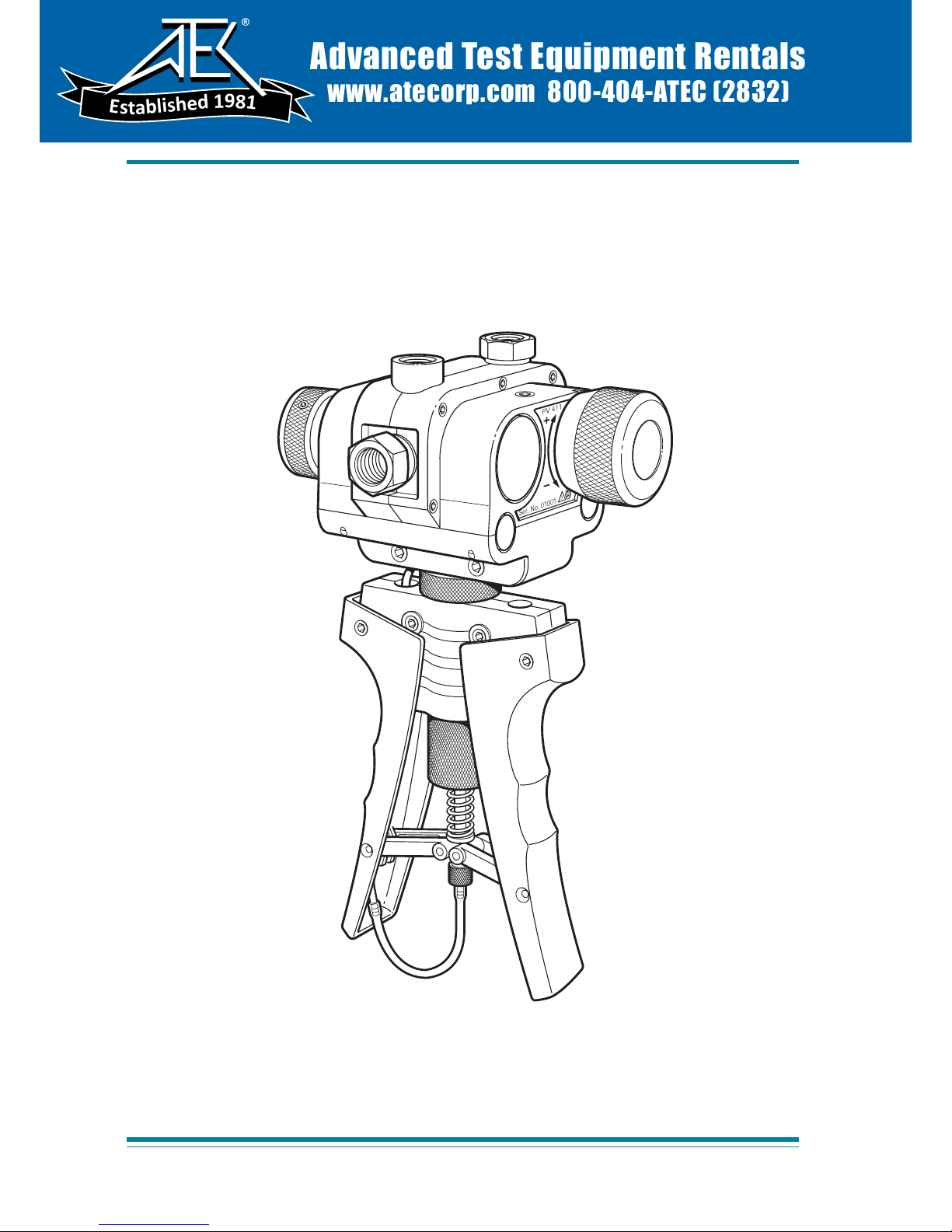
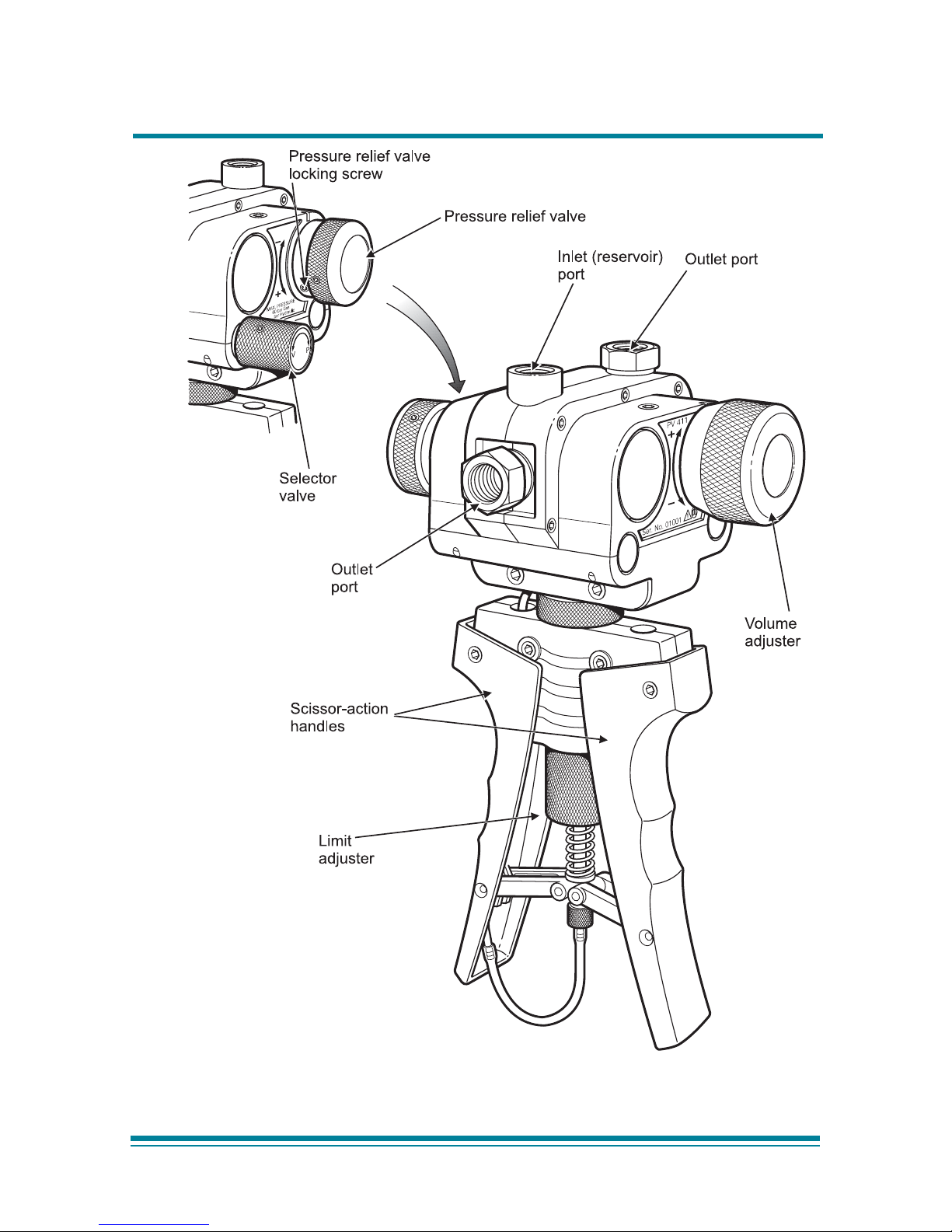
1 General iew ............................................................................... 2
2 Fitting the reser oir ................................................................... 11

Druck PV 411 User Manual
Page 1 K258 Issue No. 1
Introduction
The PV 411 hand-pump generates either pneumatic pressure and
acuum or hydraulic pressure. The scissor-action handles pro ide
pneumatic pressure and acuum generation and, in the hydraulic
mode, pro ides hydraulic pressure generation for system priming.
Pneumatic um (Figure 1)
A selector al e ents the system, to atmosphere, between
selections of pressure and acuum. Operating the scissor-action
handles pro ides the pumping stroke, for pressure generation.
A olume adjuster allows small adjustments of the system
pressure.
Hydraulic um (Figure 1)
The selector al e ents the system, to the reser oir, between
selections of pressure and acuum (used in the priming process).
The olume adjuster generates the required system pressure. A
fluid reser oir, screwed into the inlet port on the top of the hand-
pump completes the hydraulic circuit. A pressure relief al e can
be set to limit maximum pressure between 30 to 700 bar.

Druck PV 411 User Manual
K258 Issue No. 1 Page 2
Figure 1, General view

Druck PV 411 User Manual
Page 3 K258 Issue No. 1
S ecification
Pressure range
Pneumatic .........................................................................0 to 60 bar
Vacuum .................................................................. 0 to -0.95 bar *
Hydraulic ....................................................................... 0 to 700 bar
Maximum safe working pressure ........................................... 700 bar
Hydraulic fluid .................................................. Demineralised water
or mineral-based oils
Hydraulic fluids must be compatible with:
Stainless steel, anodised aluminium, nitrile rubber,
PTFE, polypropylene, delrin, acrylic and nylon.
Pressure connections: .................................1/4 BSP parallel female
Weight (approximate): .............................................................. 1.1 kg
Dimensions
Length ............................................................................ 260 mm
Width ............................................................................ 135 mm
Depth .............................................................................. 95 mm
* This alue assumes atmospheric pressure at 1 bar and will ary
depending on atmospheric pressure.

Druck PV 411 User Manual
K258 Issue No. 1 Page 4
O eration
WARNINGS
1BEFORE APPLYING PRESSURE, MAKE SURE ALL CONNECTIONS
ARE CORRECT AND EQUIPMENT IS INTERNALLY CLEAN AND
FREE FROM DAMAGE.
2M
AKE SURE THAT ALL EQUIPMENT IS TO THE CORRECT
PRESSURE RATING.
3D
O NOT EXCEED THE MAXIMUM OPERATING PRESSURE
STATED IN THE SPECIFICATION.
4O
BSERVE THE RELEVANT HEALTH AND SAFETY PRECAUTIONS.
Note
Wherever possible, use o-ring seals in the connection ports
this is the recommended method of sealing.
Pressure/vacuum Configuration (Figure 1)
In pressure mode, air/fluid is drawn in through the inlet port on the
top of the pump and forced out through the two outlet ports.
In acuum mode, the air/fluid flow is re ersed as air/fluid is drawn
in through the top and rear outlet ports and expelled through the
inlet port.

Druck PV 411 User Manual
Page 5 K258 Issue No. 1
Connecting the Pum
Connections can be made to the pump either directly or using the
range of adaptors supplied in the optional test kit.
Direct
The ports can be fitted with any suitable length 1/4 BSP male
connector, sealing either with an o-ring at the bottom of the port or
a bonded seal at the top. Fit a suitable blanking plug to an unused
port.
Swivel Adaptors
The single, 1/4 BSP, swi el adaptor connects with a range of fixed
adaptors. Using the knurled grip-feature, hand-tighten (clockwise)
the swi el adaptor, until it is fully inserted.
Swivel pump head
The pump head swi els through 140° pro iding optimum iewing
angle and bench-top operation. Placing the pump on the bench
allows greater force to be applied to the scissor-action handles.
Internal stops pre ent further rotation of the pump head.
Note
Do not use excessive force when rotating the pump head.
Selector Valve
Pressure
Turn the selector al e fully clockwise (in) position.
Vacuum
Turn the selector al e fully anti-clockwise (out) position.

Druck PV 411 User Manual
K258 Issue No. 1 Page 6
Vent
Slowly turn the selector al e to the centre position.
CAUTION:
AVOID DAMAGING THE INSTRUMENT UNDER TEST BY USING THE
VOLUME ADJUSTER TO RELEASE HYDRAULIC PRESSURE.
Scissor-action Handles Limit Adjuster
Turning the adjuster anti-clockwise reduces the stroke, turning the
limit adjuster clockwise increases the stroke.
For maximum pneumatic pressure generation, turn the limit
adjuster fully clockwise.

Druck PV 411 User Manual
Page 7 K258 Issue No. 1
Pneumatic O eration
Volume Adjuster
The olume adjuster can be used in different modes:
Low pressure
With the selector al e set to ent (open), turn the olume adjuster
fully anti-clockwise (out).
Turn the selector al e to the fully clockwise (in) position to select
pressure.
Turn the olume adjuster clockwise to generate pressure.
High pressure
Turn the olume adjuster to the mid-position. In this position fine
adjustments of the generated pressure can be made. Using the
scissor-action handles, generate the approximate pressure; then
turn the olume adjuster clockwise (in) to increase the pressure or
turn the olume adjuster anti-clockwise (out) to decrease the
pressure.
Vacuum
Turn the selector al e fully anti-clockwise (out) position.
Turn the olume adjuster to the mid-position. In this position fine
adjustments of the generated acuum can be made.
Using the scissor-action handles, generate the approximate
acuum; then turn the olume adjuster clockwise (in) to decrease
the acuum or turn the olume adjuster anti-clockwise (out) to
increase the acuum.
For low acuum use the olume adjuster only.

Druck PV 411 User Manual
K258 Issue No. 1 Page 8
Generating neumatic ressure and vacuum
Connect the pump as detailed on page 5.
Notes
Compressing a gas generates heat. Gas heated or cooled in
an enclosed volume causes a pressure change. It is
important to allow enough time for the heated gas to cool and
the pressure to stabili e.
The number of pumps required to generate a pressure
depends on the volume of the system. Therefore, keep the
system volume to a minimum.
Pressure
1 Turn the selector al e fully clockwise (in) position.
2 Operate the scissor-action handles to generate the
approximate pressure, allow time for thermal stabilization.
3 If necessary, use the olume adjuster to adjust the required
pressure.
4 After attaining the required pressure operate the scissor-
action handles to generate a higher pressure. Alternati ely, ent
the pressure to atmosphere by slowly turning (anti-clockwise) the
selector al e to the centre position.
Vacuum
1 Turn the selector al e fully anti-clockwise (out) position.
2 Operate the scissor-action handles to generate the
approximate acuum, allow time for thermal stabilization.
3 If necessary, use the olume adjuster to adjust the required
acuum.

Druck PV 411 User Manual
Page 9 K258 Issue No. 1
4 After attaining the required acuum operate the scissor-action
handles to generate a higher acuum. Alternati ely, ent
atmosphere into the acuum by slowly turning (anti-clockwise) the
selector al e to the centre position.
After completion, depressurize the pump and disconnect from the
pipes and equipment.

Druck PV 411 User Manual
K258 Issue No. 1 Page 10
Hydraulic O eration
CAUTIONS
/DO NOT MIX HYDRAULIC FLUIDS.
/ONLY USE COMPATIBLE FLUIDS, REFER TO THE SPECIFICATION.
/ONLY FIT APPROPRIATE SEALS ON CONNECTIONS.
/OBSERVE ABSOLUTE CLEANLINESS WHEN USING THIS PUMP. DAMAGE
CAN BE CAUSED IF EQUIPMENT CONNECTED TO THIS PUMP IS
CONTAMINATED. AVOID PARTICULATE CONTAMINATION.
Note
Wherever possible, use o-ring seals in the connection ports,
this is the recommended method of sealing.
Fluid Reservoir (Figure 2)
The main body of the reser oir is transparent acrylic pro iding a
clear iew of the contents.
The reser oir can be remo ed from the pump without the need to
empty the fluid, a self-sealing connection pre ents leakage. The
spring-loaded top co er seals under atmospheric pressure
conditions, but ents excess internal pressure harmlessly in the
e ent of inad ertent pressurization.
The reser oir, connects to the inlet port on the top of the pump and
supplies fluid to the pump system for pressure generation.
In acuum mode, used in priming, the fluid flow is re ersed, fluid is
drawn from the two outlet ports and through to the inlet port and
the reser oir.

Druck PV 411 User Manual
Page 11 K258 Issue No. 1
Figure 2, Fitting the Reservoir

Druck PV 411 User Manual
K258 Issue No. 1 Page 12
Fitting
Make sure that the correct o-ring seal is fitted to the inlet port to
pre ent leakage. Screw the reser oir (clockwise) into the inlet port.
Note:
Demineralised water is used to test the pump at
manufacture. On shipment, there will be traces of
demineralised water in the system.
Filling
Unscrew the reser oir co er lock nut and remo e the reser oir
co er.
Using clean, recommended fluid fill the reser oir to approximately
2/3 full.
Refit the reser oir co er and re-tighten the reser oir co er lock nut.
Connect the required pipes and equipment to the outlet ports.

Druck PV 411 User Manual
Page 13 K258 Issue No. 1
Priming the system
There are two methods: acuum priming to extract the air or pre-
filling the system.
Notes:
1 If air remains in the system, full pressure cannot be
achieved as the air in the fluid compresses. Air must be
removed from the system fluid.
2 Both priming methods require the pump to be held in
the vertical position to keep the reservoir bleed hole in fluid.
Do not allow air to enter the system through this bleed hole.
Vacuum priming (Figure 2
Connect the equipment as detailed on page 5.
Air can be remo ed using the acuum facility on the pump.
Note:
This method should not be used with vacuum-sensitive
equipment.
Turn selector al e fully out, anti-clockwise ( acuum position).
Pump until bubbles stop appearing in the reser oir, (this generates
a acuum in the system).
Turn the selector al e fully in, (this action releases the acuum and
rapidly fills the system with fluid from the reser oir).
The pump and connected system is ready for use.

Druck PV 411 User Manual
K258 Issue No. 1 Page 14
Pre-filling
Connect the equipment as detailed on page 5.
Turn the selector al e fully clockwise (in) position.
Loosen the reser oir co er lock nut to open the reser oir co er and
let atmospheric pressure into the top of the reser oir.
Open the bleed al e on the UUT.
Carefully operate the scissor-action handles to fill the system. Stop
pumping when fluid comes out of the bleed al e.
Close the bleed al e on the UUT.
If necessary, top-up the reser oir to the 2/3 le el with clean fluid.
Secure the reser oir co er by tightening the reser oir co er lock nut.
The pump and connected system is ready for use.
Setting Pressure Relief Valve (Figure 1)
The pressure relief al e (PRV) can be set at pressures from 30 to
700 bar.
If the system pressure exceeds the set pressure, the PRV opens
and ents fluid through the inlet port to the reser oir. When the
pressure decreases, the PRV closes.
To set the PRV, loosen the PRV locking screw
and turn the PRV to release at the required
pressure.
Hold the PRV and turn the collar fully
anti-clockwise.
Tighten the PRV locking screw.

Druck PV 411 User Manual
Page 15 K258 Issue No. 1
Generating Hydraulic Pressure
Note
Pressuri ing a fluid generates heat. A fluid heated or cooled
in an enclosed volume causes a pressure change. Allow
enough time thermally stabili e.
Open the selector al e anti-clockwise 1 turn.
Screw the olume adjuster fully out (anti-clockwise).
Close the selector al e.
Use the scissor-action handles to generate the initial pressure.
Then turn the olume adjuster clockwise to generate the required
pressure, allow time for thermal stabilization.
To reduce the pressure, turn the olume adjuster out (anti-
clockwise) to the required pressure.
After completion, turn the olume adjuster fully out (anti-clockwise)
and turn the selector al e to depressurize the pump. Disconnect
from the pipes and equipment.

Druck PV 411 User Manual
K258 Issue No. 1 Page 16
Multimedia
Changing from fluid to gas:
Turn the olume adjuster fully clockwise (in).
Use the acuum selection, operate the scissor-action handles to
draw fluid into the reser oir.
Depressurize the pump.
Unscrew and remo e the reser oir.
In ert the pump and, using the acuum selection, operate the
scissor-action handles to draw residual fluid out through the inlet
port.
WARNING:
WHEN OUTLET PORTS ARE OPEN AND WITH THE SELECTOR
VALVE SET TO PRESSURE, OPERATING THE SCISSOR-ACTION
HANDLES RAPIDLY EXPELS FLUID.
Pneumatic enting, after fluid use, can generate a fluid mist spray
out of the inlet port.
Flushing
If necessary, use soapy water to remo e any oil residue.
Table of contents
Popular Water Pump manuals by other brands

Power Fist
Power Fist 8533614 user manual

Aqua PRO
Aqua PRO AP550 instruction manual

BOSSCO
BOSSCO PHAH1000 operating instructions

IMP PUMPS
IMP PUMPS NMTD SAN MAX II 32-120 Installation and operating manual

Equalizer
Equalizer HP350S Operator's instruction manual

FLORABEST
FLORABEST FTP 400 B2 translation of original operation manual