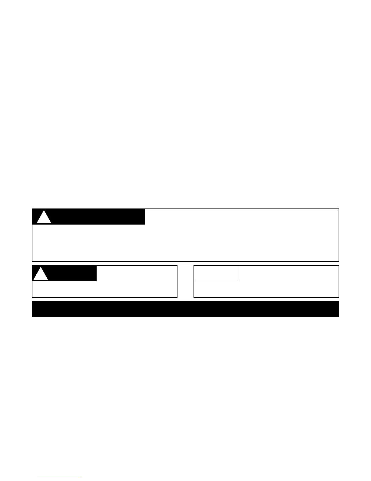
Failure to obey a safety
warning can result in
injury to yourself and others.
THE PURPOSE OF SAFETY WARNING AND NOTES IN THIS
MANUAL IS TO ATTRACT YOUR ATTENTION TO POSSIBLE
DANGERS AND THE EXPLANATIONS WITH THEM DESERVE YOUR CAREFUL ATTENTION AND
UNDERSTANDING. THE SAFETY WARNINGS IN THIS MANUAL AND ON THE EDGER DO NOT, BY
THEMSELVES, ELIMINATE ANY DANGER. THE INSTRUCTIONS OR WARNINGS THEY GIVE ARE NOT
SUBSTITUTES FOR PROPER ACCIDENT PREVENTION MEASURES.
INTRODUCTION
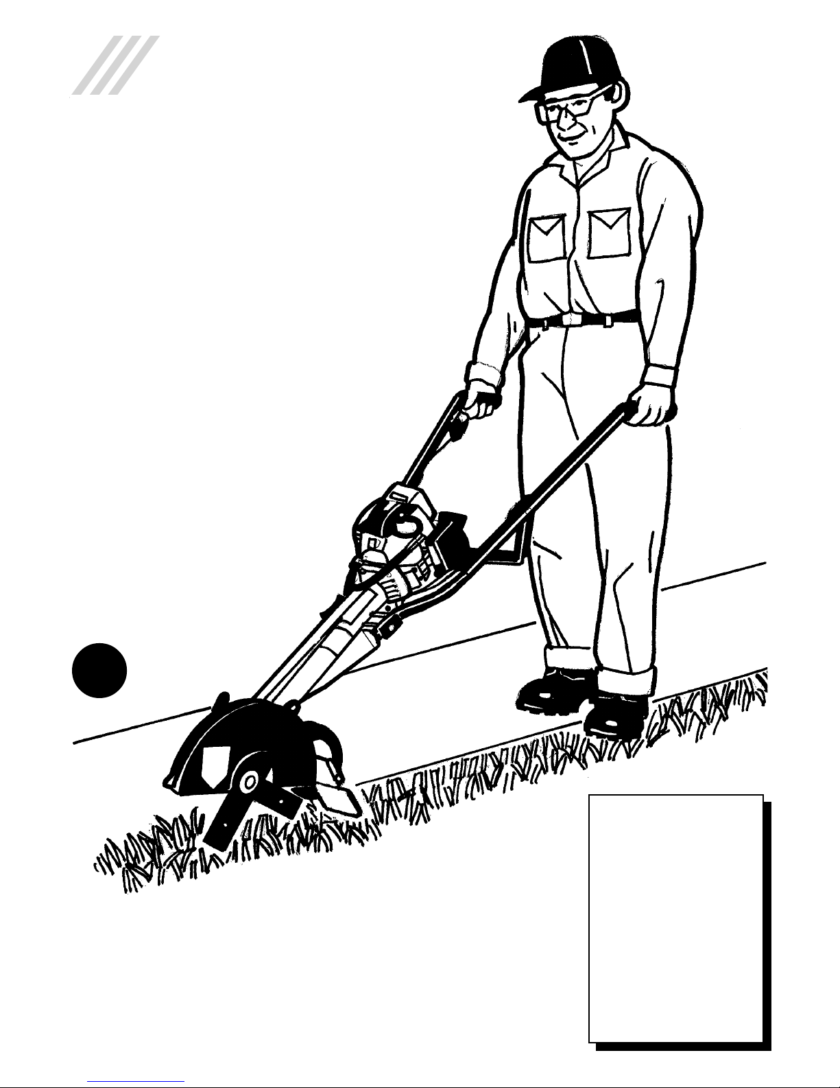
This Atom Gasoline Powered Lawn Edger is designed
to the highest standards to ensure you many hours of
uninterrupted service.
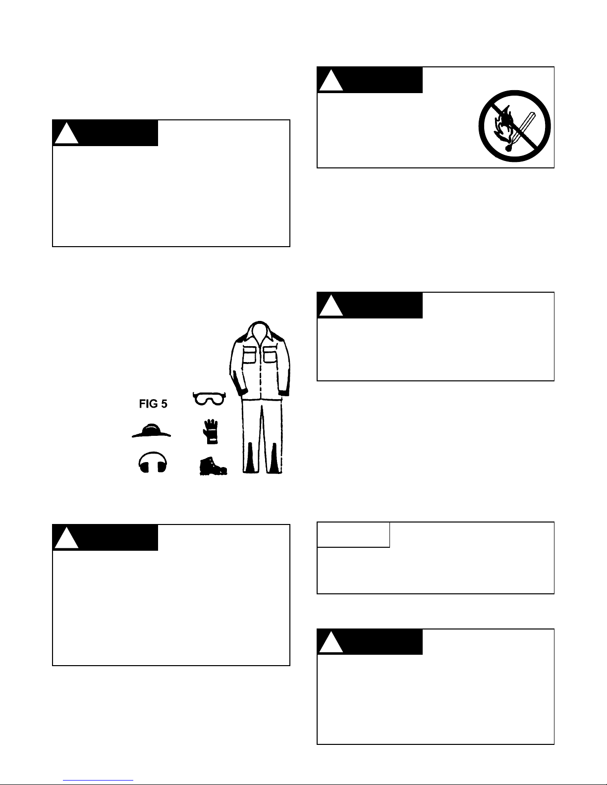
Pay special attention to the safety precautions outlined
on pages 2 to 5. Only persons who understand this
Manual are to operate the Lawn Edger.
Toreceive maximumperformanceandsatisfaction from
your Lawn Edger, it is important that you read and
understand the maintenance and safety precautions
before using the edger. Contact yourAtom dealer or the
Atom distributor in your area if you do not understand or
cannot carry out any of the operating instructions in this
Manual.
Atom’s philosophy is to continually improve all of its
products. As a result, engineering changes and
improvements are made from time to time. If the
operating characteristics or the appearance of your
Atom Edger differs from those described in this
manual, please contact your Atom dealer for
information and assistance. Call (02) 9810 0194
(withinAustralia) for your nearest servicing dealer.
NOTE: OUTSIDE AUSTRALIA REFER TO BACK
COVERPAGE.
CONTENTS
Parts and Controls ................................................2-3
Safety Precautions ................................................3-5
Assembling the Lawn Edger.....................................6
Fuel and Oil..............................................................6
Starting and Stopping Instructions .........................7-8
Edging Instructions...................................................8
Maintenance Instructions
Blade Replacement ........................................10
Lubrication of Gears........................................ 11
Spark Plug ...................................................... 11
Air Filter Maintenance...................................... 11
Removing Blade Cover ................................... 11
Carburettor Adjustment ...................................12
Trouble Shooting Tips......................................13
Parts List and Exploded View ............................14-15
Complete Workshop Manual .............................16-19
At the rear of this manual is a workshop manual for the
lawnedgerbody.ForfullHondaengine instructions and
maintenance, please refer to the separate “Honda
Owner’s Manual” supplied.All service and warranty on
your Honda engine can be done by your nearest
approved Honda dealer ....................................16-19
Warranty ................................................................20
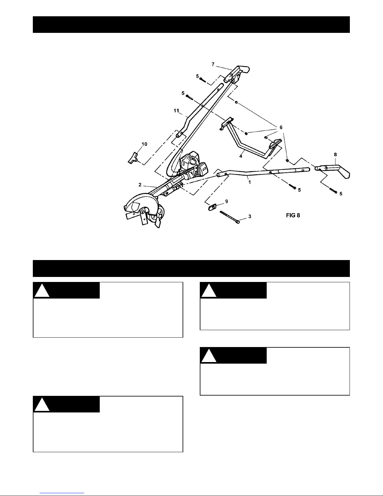
PARTS & CONTROLS
1,2 The handles of the Lawn Edger are held by both
hands.
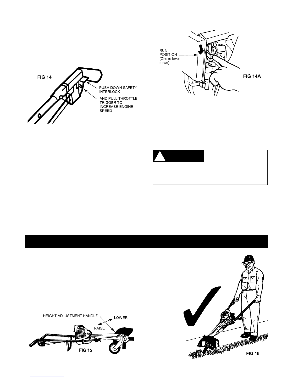
3 The throttle trigger which increases speed of
engine for automatic safety clutch to engage and
thus rotate blade.
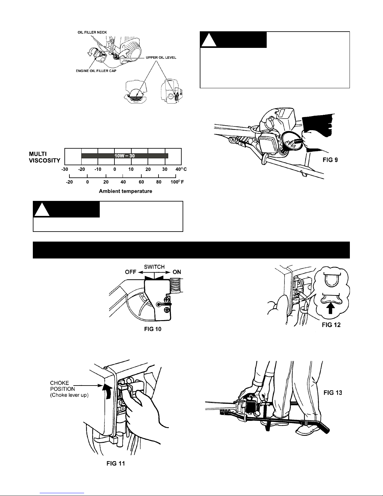
4ON/STOP switch.
5Starter grip the grip of the pull starter which is the
device to start the engine.
6Handle nut for holding handles onto housing.
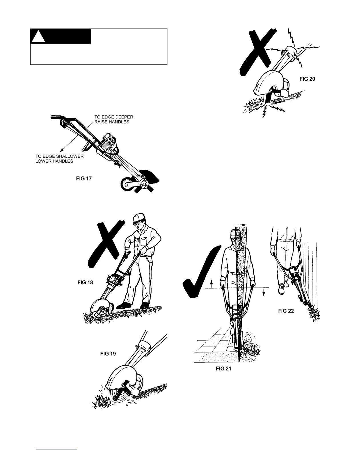
7Height adjustment for adjusting depth of cutting
blade.
8Blade cover reduces the risk of flying debris and
direct contact with the feet or hands.
9Sight guide for edging.
10 Cutter blades rotate when engine speed is
increased above idle.
11 Grass shield debris deflector reduces flyback of
stones and foreign material.
12 Wheel for moving and guiding edger.
13 Cross Brace, attaches downward on handle.
14 Left and right Handle Tubes.
15 Fuel cap, for sealing the fuel tank filler.
16 Fuel Tank.
17 Choke lever for cold engine starting.
18 Filter housing covers the air filter element.
19 Muffler reduces exhaust noises and diverts gases
away from operator.
20 Spark Plug terminal cap connects the spark plug
to the ignition wire.
21 Fuel pump primer under carburettor provides
additional fuel for starting.
22 Warning Label, on left handle.
23 Warning Label, on blade guard.
2
SAFETY WARNINGS
!
!WARNING !NOTE Advises you of information or
instructions vital to the
operation or maintenance of the equipment.