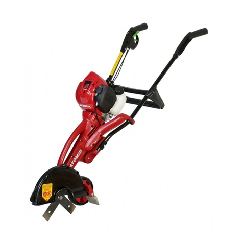
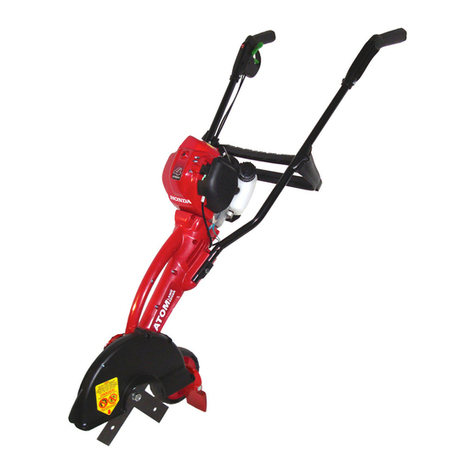
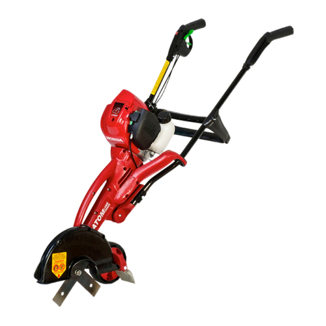
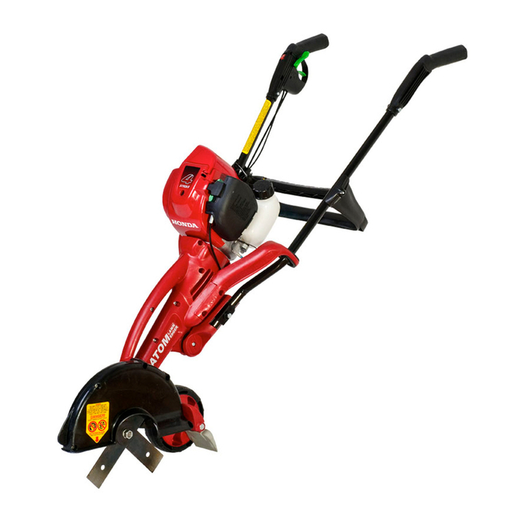
Atom 301 Installation instructions

ffiTOM'
PATENTED
WORLD€ BEST
AWN EDGERS
M.OFI
O-'
f3:lI
Electric
OPERATOR/OWNER
MANUAL
. Safety
Precautions
. Assembling
. Operating&
EdgingInstructions
o Maintenence
&
Workshop
Manual
gAcN oooss3e24
IMPORTANTMANUAL
- DONOTTHROW
AWAY
Manualalwaystobeavailable
forreference
orinstructing
newoperators.
Pleasefillin
detailsofpurchase
onbackcover
page.
ASWITH
ANY
POWER
TOOL
IMPROPER
USE
CANCAUSE
SERIOUS
INJURY
MAKESURE
THIS
MANUAL
ISREAD
ANDCAREFULLY
UNDERSTOOD
BEFORE
STARTING
OROPERATING
THISEQUIPMENT

INTRODUCTION
This
AtomElectric
Powered
Lawn
Edgerisdesigned
tothe
higheststandards
toensure
you
many
hoursof
uninterruoted
service.
Pay specialattention
to the safety precautions
outlined
onpages
2to 5. Only
persons
who
under-
stand
this
Manualareto operate
theLawn
Edger.
To receive
maximum
performance
and satisfaction
from
yourLawn
Edger,
it is importantthat
youread
and understand
the maintenance
and safety
precautions
before
using
the edger. Contact
your
Atom
dealer
orthe
Atom
distributor
in
your
area
if
you
do not understand
or cannot
carry
out anyof the
operating
instructions
in
this
Manual.
Atom's
philosophy
is
to continually
improveall
ofits
products. As a result,engineering
changes
and
improvements
aremade
fromtimeto time. lf the
operating
characteristics
ortheappearance
ofyour
Atom Edgerdiffers
from thosedescribed
in this
manual,
please
contactyour Atom dealer
for
information
and assistance.
Call(02)
9810 0194
(within
Australia)
for
your
nearestservicing
dealer.
NOTE:
OUTSIDE
AUSTRALIA
REFER
TO
BACK
COVER
PAGE
cowTE
rI'ls
PartsandControls ..2-3
SafetyPrecautions.... ...3-5
Assemblingthelawn
Edger. ......6
Starting
andStopping
lnst,'uctions
. . . . . .A
Edginglnstructions ..7-8
Maintenance
Instructions
BladeReplacement... ...... 3
Lubricationof
Gears .....3
Renror,,rngBladeCover ..,.....3
TroubleShooingtips.. . .....10
PartsList
andexpioded
View . . 18-19
lncluded
at the rea.of this manual
is a complete
workshop
manualwhar is information
for persons
withsuitable
seMcing
experience
should
thisunit
ever
require
workshop
repatr .. " 10
Warranty .. ' '.2O
70 SERVICEOR REPAIRUNIT
A, ToReplace
Driveshaft.
How
toremove
wheel
arm, ' . ' 'l
B. Motor
does
notswitch
on.
Howtoadjust
svvrtcn
cable
C. How
torepairswitch
trigger
assembly
. .. . ."''l
D. Howtoremove
and
replace
switch
cable.
r-'c:3'
clutch
and
fan ..
"'2
E. How
to remove
and
replace
mdncrown
gear
and
pinion
drive
shaft 'l
F. Replacing
clutch
drum
- Early
model.
....' .'5
Replacingclutchdrum-Latemodel
' ' '.. '5
G. Finalassembly
of
main
housing,
gear
drive
a'':
testing .ie-"7
THE
PURPOSE
OFSAFETY
WARNING
ANDNOTES
INTHIS
MANUAL
IS
TOATTMCT YOUR
ATTENTION
TO POSSIBLE
DANGERS
ANDTHE
EXPLANA'NONS
WITH
THEMDESERVE
YOUR
CAREFUL
ATTENTION
AND
UNDERSTANDING.
THESAFETY
WARNINGS
IN
THISMANUAL
AND
ON
THEEDGER
DO
NOT'
BY
THEMSELVES,
ELIMINATE
ANY
DANGER.
THEINSTRUCTIONS
OR
WARNINGS
THEYGIVE
ARE
NOT
SUBSTITUTES
FORPROPER
ACCIDENT
PREVENTION
MEASURES,
Failure
to obeya safety
warning
can
result
ininjury
toyourself
and
others.
! NOTE I Rdvises
you
of
information
or
I --- -- linstructionsvital
totheoperation
or maintenance
of theequiPment.
12
J
Thehandles
oftheLawn
Edgerare
heldby
both
hands.
The
throttle
trigger
whichstarts
electric
motor
forautomatic
motorclutch
toengage
and
thus
rotateblade.
Exterior
cordandanchor.
Warning
Labelonblade
guard.
Handle
nutfor
holding
handlesonto
housing.
Heightadjustment
for
adjusting
depth
of
cutting
blade.
Bladecoverreducesthedskofflying
debris
anddirect
contact
withthe
feet
orhands'
9 Sight
guide
foredging.
10 Cutter
blades
rotate
when
motor
is
switched
on.
11 Grass
shield
debris
deflector
reduces
flyback
ofstones
and
foreign
material,
12 Wheel
formoving
and
guiding
edger'
13 Cross
Brace,attaches
downward
onhandle'
14 Left
and
right
Handle
Tubes.
15 Motor
which
drives
theblades.
16 Cable
loop
holder.
4
o
7

PARTS
& CONTROIS(coNr//vuED)
jffi,ffffi:
DANGER!
KEEPHANDS
& FEETAWAY
--. --.
,S[N,KN
INTSJ'fN'
slJt \-r7
-7-
ROTATING
BLADE
DtRECnOilOFROTATION
WARNING.TO
PFEVET{T
SERIOUSINJURY
FOLLO{V
ALLSAFETYPRECAUT|OTS
N OPERATORIIAI{UAL
-II'PFOPEH
USECANCAUSE
SERIOUSORFATAL
ITJURY' OBJECTS
IIAYBETHROW}IORRICHOCHET
ITALLDIFECIIOI{s.
ALWAYSWEAREYE
PROTECTIO}I
. KEEPBYSTAT{DERS
ATLEASI E'FT O6II) AWAY' ALWAYSWEAREAR PFOTECTIO]I'WEAR SNUG FTTTII{G
CLOTHING
' IIIIIORIiSHOULO
NEVERBENPERilTITEOlt} USETHIS
EDGEF'WEAR STURDYSHOESWITH
I{OI+SLIPSOLESO .,O I{OTLEilO.
R€IITORSELLTHISEOGER
WTTHOUTTHEOPERATOR
TANUAL
Model No 301
Inslatbn lhEughout Double iNlat€d
Motor UnlvgEl h6ryy duty
ball bsi.E type Motor
Mouletuffi rdang:
I 350 wans
Voltao€ 23ol24 volE Ac
Air C@ling Fan torc€d
Cutting Depth Upto 75mm
Autmdiq ffitritugal
cldch Potets mior wiFn
blad€ ims q hits hatd
obi6ts whil6 €dging.
Rst{pag$5&7.
Aswithany
powertool,
theuseofanylawnedger
maybedangerous.lt isimportant
thatyou read,
fullyunderstand,and
observethefollowing
safety
precautions
andwarnings.Re-rcadthis
operatods
manual
andthesafety
instructions
periodically.
THEOPERATOR
PHYSICAL
CONDITION
Operator
mustbe
in
good
physical
condition
and
mentalhealth,and
notunder
theinfluenceof
any
substance
(drugs,
alcohol,
etc.)
whichmight
impair
vision,dexterityor
judgement
(Fig.
3). FIG3
SafeuseofanAtomLawn
Edgerinvolves:
1.The
Operator
2.TheAtomEdger
3.The
useoftheAtomEdger
Donotlend,rentorsell
thismachinewithoutthe
operator'smanual.Besure
thatanyoneusing
thisunit
underctandstheinformationcontained
inthismanual
beforcuse.
Aswithanypower
tool,
some
specialsafety
precautions
must
beobserved
to rcduce
therisk
ofpersonal
injury.Garelessorimproperusemay
causeseriousoreven
fatalinjury.
mustnotbe
opemtedby minors. Bystanders,
especially
childrenand
animals, '
shouldnotbeallowed
inthearea
whereamachine
isinuse
atleast
15
metres
(50
feet)away
(Fig.4).
Never
lettheunitrun
unattended.
Electrical
shock.
Replace
immediatelyany

SAFETYPRECAUTIONS
(co/vr//v
u
ED)
Donotoperate
theEdger
when
fatigued.Bealert
- if
youget tired
whileoperating
the machine,
takea
break, Tiredness
may resultin loss of control.
Working
withany
power
tool
can
bestrenuous.
lf
you
haveany condition
that might be aggravated
by
strenuous
work, check with your doctor before
operating
the
machine,
anything
thatcouldtrip
the
operator.
Wear overalls
or long pants to
protect
your legs. DONOT
wear
shorts.
Use
of
gloves
when
working
with the Lawn Edger is
recommended.
Good footing
is most
important.
Wear sturdy
shoes with
nonslip
soles.
DONOT
wear
sandals
oroperate
with
bare
feet, Inhotorsunny
conditions,
always
wearahatand
longsleeve
shirl
for
protection
against
skincancers,
Use
ofa
good
brand
of sunscreen
creamis also recommended
on
exoosed
skinsurfaces.
Replace
immediatelybroken
orcrackedblade
covers
and
grass
shielddebris
deflector.
A
Engine
noise
maydamage
your
hearing.
Wear
sound
barriers
(earplugs
or ear mufflers)
to protect
your
hearing.
Continual
andregular
users
should
have
their
hearing
checked
regularlY,
SAFESTARTING
Youshould
always
inspect
your
unit
before
starting
it'
Make sure the controlsand safety devicesare
working
properly.
Placethe machine
on firmground
or other
solid
surface
in
an
open
area,
Maintain
good
balance
and
secure
footing,
Failuretofollowthis
procedure
may
result
ininjury.
SAFE
WORKI
NG'A'STR
UCTIONS
ANDIMPORTANT
ADJUSTMENTS
Never
operate
your machine
if it is darnaged,
improperly
adjusted
or notcompletely
and
se:lrely
assembled.
SAFE
MAINTENANCE,
REPAIR
AND
s7oBrtG
Use only original
Atom replacement
parls for
maintenance
and
repair.Use
of parts
manufactured
byothers
willvoid
warranty
and/or
maycause
senous
orfatal
injury.
Follow the maintenance
instructions
in the
appropriate
section
of this manual. Any repairs
should
becarried
out
by
anauthorized
service
dealer
orperson
withsuitable
servicing
experience.
butallow
5). Avoid
pants,
or
Prolonged
useofany
hand-held
powered
machine
exposing
theoperator
to vibrations
may
produce
whitefinger
disease
(Raynaud's
phenomenon)
orcarpal
tunnel
syndrome.
These
conditions
reduce
thehand'sability
tofeeland
regulate
temperature,
produce
numbness
and
burning
sensations,
and
may
cause
nerveand
circulation
damage
and
tissue
necrosis.
PROPER
CLOTHING
Clothing
mustbe sturdy
and
snug-fitting,
complete
freedomof movement
(see
Ftg.
loose-fitting
jackets,flaredor cuffed
FIG5
J-
6]
Ixt
H
s
The
Atom
Edger
isaone-
person
machine.
To
reduce
theriskofeyeorother
injury
from
thrown
objects,
ensure
thatbystanders
are
at
least
15metres
(50
feet)
away
during
use.
Replace
immediatelyany
worn
orbroken
debris
deflector
shield
orblade
coven lfapproached,
release
throttle
trigger
to immediately
stop
themotor.
Proper
eye
protection
isa
must.
Theblade
cover
maynotprotect
theoperator
fromallfast
moving
foreignobjects,
even
though
the
discharge
isdirectedaway
from
theoperator,
asricochetsand
bouncebacks
mayoccur
during
lawnedging
operations.
Neveroperate
an
Atom
Edger
unless
wearing
goggles
orproperly
fitting
safety
glasses
withadequate
topandside
protection
whichcomply
with
ANSI287.1.
Always
stopthe motor,
makesure
that
theblade
is stopped,and disconnect
the plug before
adjusting
blade
height,
doing
anymaintenance
or rcpair
work,or cleaning
the unitor blade.
reUFFIG6

SAFETY PRECAUTIONS PONTINUED)
SAFEWORKINGCON
DITIO'VS
Whenworkingwith the Atom Edger,
always
wrap
andcontrol
the
law
n
edger. Do not
overreach. Keep
properfootinganl
balanceatalltimes
ELECTRICALSAFEW
1.This
doubleinsulatedelectric
edgermodel
no.
30'1
is
only
tobeusedon
240volt
power
supply.
2. Where
possible
useanapproved
Earth
Leakage
Circuit
Breaker
(Residual
Current
Device)safety
switch
atthe
powerpoint
orswitchboard,
3. Avoid
dangeroussituations.
Do not use in the
presence
of flammable
liquidsor gases
to avoid
creating
afire
orexplosionand/or
causedamageto
unit.
4. Do not attemptto repair
unit, lf thereis any
damage,do notuseuntildamage
isrepairedbyan
authorised
service
centre.
5.Damaged
supplycord
(on
lawnedger).
Thismust
be replacedby an authorisedservice
agent or
similarly
qualifiedperson
inorderto avoida hazard.
6.Never
carry
theunitbytheextensioncordoryank
theextension
cord
todisconnect
theunit.
your fingerstightlyaroundeach handle.
keep
your
hands
it JL:
5
.f -'"u
' t 1''r
/oL'r
youimachine
unde.
,t*l*!'Jo"t! l"**'-
NEVERattempt
t$.c,y-'
"1'',
rt. 4nb*,
Edger
withonehuno\r
lt ^-':') "i t
"*kl
majrresult
in seriovs
' Ll-'i "J*\ /
(Fig.
7). .I
Make
surethehar'd\.
ft itr r^t .^
good condition
6^*r
Frr
''!'
moisture,
Pitch,
oil
or q-"<r'-oe
Use both hands,
u1-a
uta
each
handle,to ope
r"f;c 7.To
reducethe
possibility
of
the
extension
corddisconnecting
from the unit during
operation, loop the
extensioncord to the
extension
cord anchoras
shown
(Fig.
B).
8. Donotusetheedger
ifthe
switch
does
notturn
theedgeron
and
off
properly,
Repairs
tothe
switch
mustbemade
by
qualified
electrical
service
personnel.
9. Keepthe extension
cord clear
of operator
and
obstacles
at all
times.
Donotexpose
thecords
to
heat,
oil,
water,orsharp
edges.
Donotedge
nextto
cord.or
wdkon
ordriveover
cord.
10.Whencleaning,
disconnect
electrical
cable
(Fig.
9) and do not use
water.Scraoedirt
away
withapiece
of
branch,
wood,screwdriver
etc.
lfaccidentally
wetted
by
water,alowto
dry
inthesun,
inspectand
ensure
it
isdrybefore
use.
1'1.Donotstore
unit
outside
butonly
indoors
ina
secure
dry
place
leaning
againsta wall
withhandles
uppermost.
INorE
I
H:?-:;'"S:T,ffi3;"?%",",.j:::y
appliances.
These
have
minimum
1mmdiameter
copper
wire.
InAustralia,
theseare
now
yellow
in
colour.
Donotuse
whitecoloured
orlight
guage
undersized
extension
cordsas
these
willcause
adrop
in
linevoltage
resulting
inloss
ofpower
and
overheating.
lf indoubt,use
thenext
heavier
guage.
Inspect
theextension
cord
before
each
useand
donotuseif
damaged
in
any
way.
Cutting
blade
cancut
extensioncord.
Keepthe
extension
cordaway
fromthecuttingblade
(Fig
00).Acutextensioncordisdangerousand
can
befatal
to youorothers.Replace
immediately
any
wornorbrokendebris,
deflectorshield
or
blade
cover.
FIG9
Donotuseinrain,
in
damp
orwetlocations,or
around
swimming
pools,
hot
tubs
etc.Donot
expose
to wate6
rain,
orsnow
to avoid
the
possibility
ofelectrical
shock.

A. Fitleft
handle
tube
#1to edger
body#2asshown,
Note:Left
handle
haswaming
labl (Fig.10).
B,Insert1SOmm
(6")
bolt
#3through
handlebolthex
headretainer
#9
then
through
left
handletube
#1
,
edger
body
#2 and
righthandletube
#11,
tVofe;Plasticretainer
#9tobepointing
forward.
C,
Screw
largewingnut#10onprotruding
bolt
#3andtighten.
D.Fitcross-brace
#4Io handles
#1and
#11withbrace
touching
ground.
Use
2 screws
#5and
2 lock
nuts
#6
provided
in
packet.
Use
straightbladed
screwdriver
(or
Tox25screwdriver)
E.Insert
triggerhandle
#7intoright
handletube#11usingone
screw
#5andone
nut
#6tohold
in
place.
Note:
Throttle
cable/switch
wirefromengine
must
befittedunder
handleandclipped
intoholdinglugsofcross-brace
#4.Donotloopthrottlecable/switch
wire
over
handle.
F,Insertlefthandle
#Binto
lefthandletube#1usingone
screw
#5andone
nut
#6
tohold
in
place.
5___-__\
'07-
t<' FIG
10
NOTE:
Donot loop throttle
cable/switch
wireoverhandle
\ o__________-
To
start
motorholdfirmlyleft
andrighthandle
grips
andensure
baldeisoutofground.
Withright
thumb
press
down safety
interlockand pull backtrigger.
Motorand blade
will instantlvstart
toturn.
To stop
release
trigger.
6
motor
throttle
Never
useunitonwet
grass,
inrainyconditions
il grass,ln ralnyCon0ltlOns
or wherethereis dew or moisture
around.Never
hoseunit
withwater
toclean.

1,The
edger
isvery
easyandsimpletouseandmost
operatorscan
immediately
adapttoits
unique
flexible
USE,
For some peopleit may take a few edgingsto
become
accustomed
to its
operation.
2.Thoroughlyinspecttheareawheretheedgeristo
beusedand
remove
allstones,sticks,wiresandall
other
foreignobjects.
3. Adjust
bladedepth:
Try
second
hole
closestto
operator
(Fig,
12)
! NOTE I Failure
to adjustbladeto correct
- | edging height will cause
overheatingof motor and clutch due to blade
rotationstopping.
! NOTE I When cutting efficiently,
motor
- | willturnbladesathighspeed.
4. Withbotharms
fully
extendeddownwards
(see
illustration
on front
cover)
holdboth handle
grips
firmly,
The
bladeshould
just
clear
the
ground.
The
blade
is
now
set
high
soitcan
only
cutif
you
lift
your
arms
slightly
(100mm)(Fig
13).
7, As cuttingactionbegins,
movethe lawn
edger
forward
sothatthe bladecancut theedge
asyou
moveforuuard
(Fig.
15).
8.Continue
atamoderate
pace
untilyouare familiar
with
the
controlsandthe
handling
of
theAtom
Edger,
9. lf
blade
jams
orstopsinthe
ground(Fig.
16),lower
handlesor pull
backunitandrecommence.
Motor
shouldbeatfullsoeedunder
load.
x
FIG14
RAISE
TO
EOGETEPER
FIG13
5.
Pull
throttletrigger
allowing
motor
tostart,You
can
practice
walking
fontrard
onanareaofyour
lawnor
garden
slightlylifting
your
arms,
holding
handlesfirmly
for
the
blade
tocutinto
the
ground.
This
will
giveyou
a"feel"
oftheoperating
technique.lfno.2 position
is
toohighthenset
atno.3
position.
6. Do not lift handlesby excessive
bendingof
elbows (Fig 14).Always keep arms straightas
shownon Front
Cover.
! NOTE I Allowingmotorto runexcessively
' l (1-2 minutes)
with bladesnot
rotatingwill
causeclutch
to burnout.
Only
operateunit
when
movingforward.
DONOT
operatewalkingbackwards,
as
youmay
trip,fafl
and
injure
yourself.
FIG15 FIG16

EDG
I
N
G ttYSfFUCT
IOltlSrcoru
rNu
ED)
1O.Edging
along Concrete
edge:Forposition
of
blade,
align
edge
guide
(at
frontofblade
cover)
with
edge of concrete.lf blade hits concrete,
lower
handles
and re-position
blade
at sideof concrete.
Even
withthe grass
growing
over
theconcrete
and
you
cannot
see
theedge,
youcanfeeltheedgeof
the concretewith the rotating blade by slightly
sideways
tilting the handlesof the edger away
fromthe concrete
so that the blade
tiltstowards
the concrete and touches or "kisses" the
concrete
edge
and
acts
as
aguide
(Fig
18).
Edger
blades
are
made
from
high
tensile
hardened
spring
steel
andwilllast
a longtime.
Once
the edge
is
established
the second
and subsequent
times
around
are
very
fast,
11.Edging
against
wallsor fences:
Tosideways
tilt,
lowerone
hand
and
liftother
hand
and
slowly
walkalong
wallor fencecutting
theground
just
below
ground
level
(Fig.
19).
12.Clutch:
The Atom Edger
is equipped
with a
centrifugal
clutch. DONOT
run edger at low
speeds
(or,
if blade
isjammed,
andmotor
isstill
switched
on.Stopmotorand pullbackunitand
recommence
edging.Reducecutting depth as
clutch shoes will prematurelywear and cause
damage
ifcuttingbiades
do notrotate.
! NOTE I xeen
inside
of
blade
guad
clean'
clogged
guard
can
slow
down
orstop
blade
rotation
andmaycause
damage
to automatic
safety
clutch.
Always
operate
blade
athigh
speed
when
edging.
13.
The
Lawnedger
can
betransported
by
pushing
it
onit's
wheel,
orcarrying
itwith motorswitched
otf
as
inFig,
17
FIG
18 FIG
19
TNJURY
NEVERCARRY
THE
EDGER
WHILE
THE
MOTOR
IS
RUNNING.
Never
hold
the
handlecross
brace
if
the
motor
isrunning
(Fig.20).
Stop
themotor
Prior
to
lifting
orcarrying.
FIG17
FIG
2OA

BLADE
REPLACEMENT
'1
, Blade
holdingnutcanbespun
off
with
an
impact
drive.
Alternatively,
stop motor. Clean
areaaround
dust
cover
#43770and
pry
out
withscrewdriver
(Fig.
21)
exposing
14mmhex
headforunscrewing
blade
nut.
FIG21
2. Throughdustcover
hole,
place
14mmsocket
and
place
17mmwrenchonblade
nut
(Fig.
22),
FIG22
3. Unscrew
nut counter
(anti)
clockwise
(normal
right
handthread)
(FiS.22).
4. Remove
onesmallwasher,
onelargewasherand
twoblades
(Fig24),later
modelsdonot
have
smallor
large
washers
(Fig.
23& 24).Before
installing,
clean
all
grit
and
grease.
Assemblethese
parts
cleanand
dry. Fitlargewasher
(only
on early
models),new
blades
withspiggotsof oneblade
interlocking
with
holeson opposite
blade,large
washer,
one small
washer,
andnut.Tighten
nut
to 15-20ft. lbs.
(20-
27Nm)
or handtight with 8" (200mm)
or longer
soanner. FIG23
Early
Model
FIT
BLADES
AT
RIGHTANGLES.
2 SPIGOTS
ONEACH
BLADEFITINTOHOLES
OFOTHER
BLADE
5. Clean
plastic
dustcapand
housing;
press
back
by
gently
tapping
into
place.
Clean
insidebladecover
ofany
builtupdirt,or
withimpactdriver,spin
nut
on.
TOREMOVE
BLADECOVER
LID
Forcleaning
(or
majorrepair).
1.Liftandtap
with
hammer in a
clockwise
direction
(Fis,
25
-A),
2.
To re-install, FIG
25
press
down lid in centre
and tap with
hammercounter
(anti)
clockwise
(B).
IOOSE BLADE
Followsteps
'1
and 2 of Blade
Replacement
and
tighten
nutclockwise.
LUBRICATION
OFGEARS
Only
required
if
gearbox
shows
leakage
orisnoisy.
There
is usually
sufficient
grease
to lastat least5
years
before
topping
it up.Thegrease
in the gear
caseshould
beadded
to according
to use.Use
a
light,free-flowing
lithium-based
grease
such as
Castrol
EPLI
or itsequivalent.
Thisis available
ina
handyto usesqueeze
packwith nozzle
(#43227).
Removetwoscrews
marked
FILL
andBLEED.
Inject
grease
intoFILLscrew
holeand
allow
grease
toeject
fromBLEED
holeindicating
gear
box
is3/4full
(Fig.
26). Refitand
tighten
BLEED
screw and
squeeze
in
3to
4 more
lotsof
grease. Refit
FILLscrew
and
tighten,
NOTE:Donot use
lightor heavy
gearoilas it might
leakout. lf gear case shows leakageuseheavier
grease
(e.g
Castrol
EPL2).
lf case
ioint is damaged,
cleanand dry and use a gasket sealant.
Replace
o-ring
ifdamaged.
Tightenallsrews.
Refillcasing.
USE
ONLY
ATOM
BLADES.
Otherblades
havelarger
size
holes
(112"1which
willcause
out-of-balance
vibrations
whichwilldamage
unit
andcause
injury.Other
blades
canalso
breakand
cause
major
injury.
! NOTE I Donotrun
motor
withoutblade
' I tightened
to blade
shaft
as
gear
damage
willoccur.
Alwaysusetwo blades
as
shownabove.
Neverusea single
blade.
Donot
useother
thicker
bladesasyouwill
damage
theunit.

Problem Ret.
'1. Cuttingbladedoesnot
turnwhenoperating Blade
cover
filledwithdirVgrass
Clutchslipping
Looseblade
nut
Blade
stoosunder
load
Clean
Cutlessdepthorclean
Tighten
blade
Cutless
depth
PageT&8
PageT&8
Page
9
PageT&8
2. Gearcase
Leaking Loose
screws
Broken
"O"ring
Leaking
aroundscrew
thread
Tighten
Replace
Re-fix
screw Page
9 & 16
3. Noisy
gears Nooilingear
case
Loosebladenutorgear
adjsutment
incorrect Refill
Re-assemble
parts correctly PageI & '16
4. Heawvibration Wrongbladefitted
Wornclutch
Wornclutchdrumordamaqeddriveinsulator
OnlyuseAtomBlade
(P/N
43782)
Taketo servicedealer
Taketo seryicedealer
5. Motorwillnotstart Notconnectedto power
Safetyswitch
- earth
leakage
circuit
breaker
(Residual
currentdevice)
not
on
faultylead
Motorswitch
ormotornot
activiatinq
Motordamaqed
Reconnect
Clickto 'ON".
lfit
continues
tocutout,check
cables,
house
powerpoint.
Orhouse
safety
switchcould
befaulty.
Taketo servicedealer
Take
to servicedealer Page
11
6. Motor
lacks
ooweror
bladestopsrotating Cutting
toodeep Raisecuttingdepth Page 7
7. Leakingoilatdust
COVET Overfilled
gearbox Cleandustcoverand
casing,cover
leaking
areawithsealantsuchassilicon
orgasket
cementand
refit.
B. Hot
extensioncord Using
light
dutyeKensioncord Usea heavier
gauge/heavy
duty
extensioncord Page7
! NOTE I Thisinformation.is.for
persons
withsuitableservicingexperience
should
this
unit
- I everrequireworkshoprepair.
A. TO REPLACEBLADESHAFT
1,
After
removing
blades
(Refer
Pg9,Figs21-24)
removeblade
drum#431
12,feltseal
#42112andspringbevel
washers#43115iffitted.
lnsoectthreadedendof
shaft
andfileoffanyrough
surfacessoshaft
isround
andsmooth.
2.Hold
unit
as
shown
in
Fig.27andtapshaft
throughusinga3/8boltor
similarsothat
boltreplaces
shaftandmaintains
alignment
and
contains
washers,
spacerand
gear
insidehousing
- DONOT
TURNHOUSING
OVER,
\f,.
70 SEFVICE OR REPAIRUNIT
A. ToReplaceDriveshaft.
Howtoremovewheel
arm. . ., 10
B. Motordoesnotswitchon.Howtoadiust
switch
cable .,,,.11
Howtorepair
switchtriggerassembly.. . .. . 11
Howto remove
andreplaceswitch
cable,
motor
clutch
andfan ...12
Howto remove
andreplace
main
crown
gear
and
pinion
driveshaft ...14
Replacingclutchdrum
- Early
model.
. . .. . .15
Replacingclutch
drum
- Latemodel... ., ..15
Finalassembly
ofmainhousing,
gear
driveand
testing .1617
D.
E.
I plug beforedoingany
or repairwork,or cleaningthe unit
10
FIG28

COMPLETE WORKSHOP
ilIANUAL poNnNUED)
3.Carefully
push
new
bladeshaft#43114
up
into
bearing
and
tapthrough
carefully
sowashers,
crown
gear
and
spacer
remain
in
position
and
the
3/8boltis
pushed
out
(Fig,
28).
4.Whenblade
shaft
comes
through,
turn
assemblyover.Tap
bladeshaftsohead
of
shaftisagainstbearing.
TOREMOVE
WHEELARM
1.Removeone
screw
and
washer
through
holeinbladecover
(Fig.
29A).
Pullwheel
arm
assemblyoutof
edger
body.
2.Remove
bladecover
lid
by
lifting
andtapping
in
aclockwise
direction
(Fig.
2e).
B. ADJUSTING
INNER
AND
OUTER
MOTOR
SWITCHCABLES
lfthemotor
does
notswitchon re-adiust
cableas
follows.
Loosen
2 screws.Pull
blackouter
cableoutwards.
retightenscrewsin
this
position.
Motor
shouldnow
switchon,When
you
switch
on
you
canheara"click"
in
the
motor
casing
(Fig,31),
stool for ease of
working
(Fig.
36).
FIG
31
C. TO REPAIR
SWITCH TRIGGER
ASSEMBLY
1, Remove2 screws
(A)
as shownin Fig
3'1and
remove
coverandall
parts.
Re-assemble
as
follows,
2. FiIswitchinter-lock
andcompression
spring
(Fig FtG
g6
32\.
3. lf fitted with
switch trigger
torsion spring,
place torsion
springover post
and hold back
with thumb (Fig.
33). Fit switch
trigger fully over
post and release
springsoitcatches
throttletrigger.
4. lt fitted with
switchtrigger
with
too hook #43288
and switchtrigger
compressionspring
#43198,fit trigger
then comoression
spring
(Fig.34).
5,Holdtriggerin
place with finger
until switch
cover#44069 is
fitted
(Fig
35).lt is
then ready for
screwingtight
(with
2 screws (A) as
shown
in Fig
31).
Ensure switch
cover rear lug
(arrowed
Fig. 35)
engages
underside
of
handlewall.
D.HOWTOREMOVE
ANDREPLACE
swtTcH oABLE,
POWERCABLE,
MOTOR CLUTCH AND FAN
Stand
unitagainstbenchor
wall
as
illustrated.
Use
a
FIG29A
FIG29B
FIG
33
FIG34

COMPLETE WORKSHOPMANUAL PoNTINUED)
UseTox No.25Screwdriver.
Do not use straight
blade
screwdriver
asit
will
strip
groove
inscrew
head.
remove
rear
cover
4 screws.
Remove
innercasing
4screws.
Disconnect
throttleswitch
control
leverby liftingout
withthrottle
cable.
Remove
2 wiresfrommotorby
carefully
pulling
off
motortags.
Remove
wiring
loom
assembly,
+ 4SCREWS
4 SCREWS
4SCREWS
TOREMOVE
MOTOR
TO REPLACESWITCHCABLE
1. Loosen2 switchtrigger
coverscrews
(A),
Pull
outer
cableforurardand
liftinnercableand
lug
out
of
slot
incover
(Figs
38&39).
2.
Toreplaceswitchcable,
reverseabove
procedure.
Outer
cablemustbepushed
fullyinbefore
screwing
down
coverscrews
(Fig.
40).lf
motordoesnotswitch
onsee
(B)
Fig,31,
P.11.
3. At motorend,liftcable
out of casing
procedure
toinstall
(See
Fig.40A).
zzzzzzz WHITE
EEEEET11 LIGHT
BLUE
tEEIAp BRowN
- !^-roru-
:xBf'"'
TO REPLACE
POWER
WIRE,CABLE,
SWITCH
ANDLEADS
1. Remove2wiresblue/white
from
motorby
carefully
pulling
upmotortags
"A"
(Fig.
aOA).Remove
wiring
loomassembly.
reverse
ZZZZZ wHtTE
EEEEEEI LIGHT
BLUE
4l BROWN
- DARKBLUE
FIG38
FIG39
FIG
40
tz
FIG4OB

COMPLETE WORKSHOPMANUAL poNrtNUED)
TOREMOVEAND RE.INSTALL
MOTOR
1.Remove
4 screws
holding
motorand liftmotor
assembly
out
(Fig.
43& 44).
CLUTCH
Theclutchis a 2 shoespringless
type.lt is self
adjusting
forwear.lfitisbadlyscored,
wornorburnt
due
tooperator
runningmotor
withoutbladeturning,
removeby knockingto spinoff.
Anti-clockwiseto
remove,Clockwise
to replace.
lt is selftightening,
Before
installingmotorandclutchto unit
place
very
thinpackaging
tape (eg.
cellotape)overshoes
as
illustratedso
it
canbe
installedeasilv
into
clutch
drum
(Fis.
45).
Removeclutch
to test
motor.Only
run
motorand
clutch
togetheronty
if installed
conectly
inedger
body.
FAN
lfblades
broken,cracked
orpieces
missing,
replace
byleveringoffcarefully
and
tapping
new
fanon.
MOTOR
lfmotorwas
working
previously,
re-installcarefully
by
placing
4 screws
in4 corners
of motor
mount
and
carefully
lowerintobody.
Tighten
screws
criss-cross
untiltight,
25 inch/lbs
(2.5NM).
Makesure
clutch
shoes
fitinsideclutchdrum.
! NOTE I lfmotor
hasbeenburnt
out,
eg.
' I commutater
orwiring,
itcan
be
replaced
withanewmotor.
! NOTE I Check
commutater
forweal
' I burnt,
roughor
missing
pieces
and
iffound
inthis
condition,
motorshould
be
replaced.
The
brushes
are
verylongand
willlast
along
timeifcommutater
in
good
condition.
1e
! NOTE I lfmotor
cannot
be
pulled
out
- I afterallscrews
areremoved
itis
possible
thedouble
insulation
protection
polymer
materialhasmeltedcausing
shoesand
clutchdrum to fusetogether.
Toremove,
proceed
to "Remove
Gear
and MainAssembly
Shaft"Page14.Removing
shaftfromcasingalso
allowsmotorto be extracted.
! NOTE I Later
clutch
assembly
hub
also
- | actsasaelectrical
insulatorand
asafetydevice
ifoperator
overloads
motor,
continuous
jamming
ofblade
andoverheatingof
motor.
Hubwillmeltand
protect
motorlikea
fuse.

COMPLETE WORKSHOP MANUAL poNnNUED)
E. HOWTOREMOVEAND REPLACE
MAIN CROWN
GEAR
ANDPINION
DRIVESHAFT
REMOVEWHEEL
ARM
1.Remove
blade
cover
lid
by
lifting
andtapping
in
a
clockwisedirection
(Fig
47).
FIG47
2. Remove
onescrewandwasher
through
hole
in
bladecover
(Fig
48).Pullwheelarm
assemblyoutof
edgerbody, t
! NOTE I Following
onlyapplies
toearly
- | modelswith
polymer
clutch
drum
if it isto bereplaced.
Referalsoto "Removing
and
Replacing
ClutchDrum"late model
(P.15).
REPLACING CLUTCH DRUM AND
REMOVING SHAFT
1.Removeblade
coverlidandwheel
armasshown
Fis.
a7).
2.Remove 7x screws holding main blade
cover/bearinghousing,
(Fig.
50).
3.Turn
edgeroverto removedustcover
(Refer
Pg
9,
Fig21),
4.Withasoft
punch,
taphexendof
bladeshaftas
in
Fig.49 untilcoverandgear
assembly
pops
outof
body
housing.
FIG
50
5. Remove
bearing
holding
screw
(A)(Fig.50).
6.Using
a screwdriver,lever
pinion
back,turn
screwdriveronedgeto force
back
further
(Fig.
51&
52).
7,Witha copperor brass
punch(a
7/16"
brassor
coppershaftabout10"long),holdhousingandtap
pinion
shaftout
(Fig.
53).
! NOTE I DONorusEASrEEL
DRIFr
- | asa punch
as
youwill
damage
thepinion
teeth.
w*

COMPLETE WORKSHOPMANUAL lcoNnNUED)
REMOVINGAND
REPLACING
CLUTCH
DRUM- EARLYMODELS
'1.
Removemain
drive
pinion
shaft
asabove.
2,Remove
3/16x1
"roll
pin(P/N
43184)
by
punching
out(Fig
47).
Slideoffclutchdrum,check
shaftand
straightenif neccesary.
Slideon new hub/drum,
carefully
line
uphole
and
re-fitwithnew
pin.
FIG
54
TOREMOVE PINION
l. Hold shaft in vice
betweentwo piecesof
aluminumso as not to
damage
shaft.
2.To
remove
pinion,
grip
shaft
just
behind
bearing
injaws
of vice
(Fig,
55)
and unscrew oinion
counter
(anti)
clockwise
(normal
thread)withvice
grips. lf tight,heat
to
break
loctite
seal,
3.Fitnew
pinion
withfreshloctite
on
thread,making
sureitis
tight
uptospacerwasher
#43229,
(Fig.
56)
andwasher
doesnotmove.
SEALANT
wAsHER PN 43177 I
! NOTE I Later
models
donothave
- I washer
(P/N
43177)
fitted.
REMOVINGANDREPLACING
CLUTCH
DRUM. LATEMODELS
1. Thereis no requirement
to removemaindrive
pinion
shaft,
2. After
removal
ofmotoruseanextensiondriveoran
impactwrenchfittedwith
a9/16"socket
(Fig
57),
! NOTE ITheclutchhubonlatermodels
- | isthe
electricalinsulator.
ltis
alsoasafetydevice,
ifoperatoroverloadsor
overheatsmotor
bycontinuous
jamming
of
the
bladeitwillmelt
and
protect
motor.
! NOTE I Toreplace
completeshaft
- | followinstructions,Page14.
! NOTE I Clutchdrum
hub
on
early
-J models is an electrical
insulator.lt isalsoa safetydevice,if operaotr
overloadsoroverheats
motor
bycontinuous
jamming
oftheblade
itwillmelt
and
protect
motor.Howto remove
(Fig.54).
! NOTE I Remove
clutchdrumand
- | replace.
Onlyhand
tighten
flange
clutch
nutorvery
lightly
withimpact
wrench.
Overtightening
withimpactwrench
cancausebearing
to moveforward
excessively.
FIG55
FG56M+
IA

COMPLETE WORKSHOPMANUAL GoNTINUED)
F. ASSEMBLINGOF MAIN HOUSING,
GEAR
DRIVEANDTESTING
1.
Clean
anddrypinion
bearing.
Placeoilresistant
gasket
sealant
(e.9,
Fullerprene
303)
aroundbearing
(Fis.
56).
2.Hold
pinion
shaft
assembly
verticallyandslide
into
casing
Aand
B(Fig,
59).
3. With
a softpunch
drive
shaft
to bottomofcasing
(Fis.
5e).
4.Fitbearing
screw
(Fig.
50).
5. Lever
pinion
backto holding/locating
screw
(Fig.
60).
6. Replacecrown
gear
ifteeth
are
worn,See
sequence
of assembly
(Fig.
61 - earlymodels,Fig. 62 - late
models).
7. Check
and
renew
'O'ring
#40906
ifnecessary
(no
'O'
ringftted to latemodels).
Fitassembly
into housing.
lf
bearing
isloose
inhousing,smear
loctitearound
bearing
before
assembling.
Carefully
drive
down (making
sure
gears
are
meshing)by
gently
tapping
around
bearing
area
(Fig.
63)andturning
clutch
drum.
Refit6 screws
around
shaft.
8. Fillor top up with gear lubricant.
See Page 9
..
LUBRICATION
OFGEARS'.
9. Fitblade
(see
page9) and bearing
cap and check
rotationthat gears are not binding. lt should turn
smoothly
from clutchend. Backlash
at end of blade
about2-4mm.
Refitblade
cover lid,engine,
handles
andtest.
T
I
NF
BLA
enl
W2 WASHERS
EARLYMODELS.
FIG61
LATEMODELS
FIG62
6mm
(.236")
lr
o
rd
e
L:
Bearing
Laatjng
Screw
! NOTE I Bearing
mustbe
forward
toallow
' I bearing
locatingscrew
to be
fitted,then pinionand bearing
forced backonto
screw.
lfthis isnotdone,
pinion
orcrown
gear
couldbetight.
Correct
distance
is6mm(.236')
Fig.60.
to
FIG60

COMPLETE WORKSHOPMANUAL lcoNrtNUED)
TOCOMPLETEASSEMBLY
Replace
motor
power
cableandswitch.
Replace
switchlever
andcable.
Replace
inner
casing.
Replaceouter
casing.
Reolacehandles
etc.
TESTINGOF UNIT
MotorandOn/OffSwitch
Afterfullyassembling
and connectingto a power
source
preferably
fittedwithanearthleakage
circuit
breaker,
switchunit
onandoffseveral
times.
lf
switch
does
notswitchon or off.checkthrottlecontrolto
makesureit isfree
andnot
jamming
andadjusted
correctly
(see
page
11 - Fig.
31).
lf notworking,
disconnect
power,
re-checkall wiring,including
oables,
earthleakage
circuit
breaks
etc.
resting
Clutch
vVhenedging,
jamblade
inearthand
motorwill
still
.un
at
low
speedwith
aburring
noise.
Only
dothisfor
afewseconds,
17

o
a
(l)
E
(U
o
E
o
I,I
tl
x
z
F
LL
t
LU
o
:l
i:i
ltr
;i.Y
lo
iI
l.im
! i :uJ
IILIJ:O
i OL!
. *d
-: HX
-rrt-t rn.#
g:g:8
r
=i= tr a1
-:ixX
LUIU-t,Ul ,LU
J:J]JiJ
^:aA^
ZlZlZtZ
<!<,< <
I;I]I:I
itii:O
. ' | (
::::
i,go
: i)< (Y
:rY: ^
" i=i:, X
:d:.-
6
-.l.i,
! Fi;i5
_,
=
O ^t= lzt< o-
=
U:SiX:8
F
Tnl:-
+
U:3i=:E
!
6 E,miS:+
Z
n: CcluJ:ri>
<
- F J:V:trtT
Hiii2i9iPr
ilil.frd.5E
X: txi l
j--.,iii
ifii ii
iQi :li
j=l il
iN: :t
i;i :i
:^:
i-: I i c!
,i r,cr =
:;i LiJ:
LLI
:" >.> =
.(5 u.]ul =
cI-:1
'l- ,,'?,
HitrPiPR
e
E.B
E.E:EJ
I l(/)l : i
llO: il
:7:x
i-l ;:
I l+i : :
tlFi i:
lloi ir
lrml I
Qt ,<i '
J:tti :
rn, t=t i,r
-L: :rL! lZ ^
-::,::Js
)>: :Fi ,a z-
i'e,k.>'5
ffi
?itilili+ O
u q'.:wr:t+:) J
CDIg:6:t-.::2 g
7t ,tr:I'LU r-
=i=iF.9iq0
^:v v:!.4 -
V.Zru.l
-'i
< >
Oio-ldrc->
d 6
jix
:l
F
,tr,
.h'1r<
t-tz
o,tri5
cri,>.r
*;d.P
;'>i;',
.d.!l.Z
Fi?i3
\/:tttL
9.=.=
=tZi!)
t,+i=
6'r.3
Xii:
il
:
-Jl
<:
Zl
=i i
lY: I
LIJ:
F:
;,,>
Z:m:
o.>.
trt LIJ
=.tn
=<
u :Cf
?i?i
00!O-
t+
F
t
sOir;N $
(o:(ot(oi(o
Si$:sf $
sis:s $
l.-
ic9r$itr):@.o
(O:
N: N i
F_:t_ F_
$l\ti$:\li\f:$
$i$!$:s:$:$
Ni@r$!F:N -
NIO):(O:(OrN f.-
NrO l'-!l'-:N r
m-m:dmm
.f llr)r*f i$t$r$
r.ot(otc9
S: f.- i f.-
N:r iF-
cDlcDicY)
si$t$
O)iC)iN
co:(oro
NiF f.-
$ist <'
tr)i(oiN:ot!s
(Olo)
iS iS lO)
@it-tN:f.-;N
cDlc):C9!cr)!ct)
+l+i+i$:$
t+
d
Yr.-
rO Lr)rtr)i(O F iN rC)
(o: (o i
co
i
:filf)i(o
(ot(o (o N@iO)iOi-:N
(O: (O i lr* i lr-: F- r.- $iLr)
t.- i lr* (o: f.- l @
f.-:f.-rl.- O)tOiriciticr)r
l.-icorco:co:co
i."i
iii
ilr
l-Ji i
i:$' rq
3,E'iE
t+:Lu i il.JJ
LU:F: I)
Fii.
t:g
e:= ia6
=ii.sig
;i=if;i=
F
E
trDi(.):o
dr$io
\ININ
<li$itf
N
rr)
f--
.if
s
tr)
N
$
(or@!oiN
Lr)ltr)i(o:(o
t* i
N: t-: F-
6i6:dim
$tsisis N
s
$
@
f.-
$
tr):N
@:@
N: l.-
cDi cf)
s itf
oJ
N
r$
F*
1.,-
I
N
t-
t-
$
N
f.-
s
O:r:stl@
Nl@i@t@
F-; N: l.- i f.-
cD!c.)icr)!c')
$:3iS:$ t.,-
s
-:N:@:O (O:tf)
o)
io):o)
i(o:o ie)
t-iNir.-:@iOiO
CD!c.).CDiCT)'$i$
S:S,$jS $iS
d
\( Noi-
cDi c') c\ $ tf)t(o:N
c)!cDicDtcr) Olr
rit:$ N
Iss
str)
s(o i|..-:@ i
o)
9:SiS:S Lr) -lNiCD:3irO
[o:tr)itr):ro]rr) tr)
i ixrx
iil
iii
iji
i i=,
Fi t>i
FiE{.
liE:r:
a:P3. ,
i,i'?,fr
=ia:: :J
ii2'?'E
t:iii
iX! i lXiX
iiiil
>l iii.
>: iri,
(Oi : ; i l
.: ! : !
I. i i !J,r.!
+,N: i,.,ii
I
ii;i i>:=
<
O):^'l
ul;;, !Otg S
a, xt=iF:+ +
*iur5i*iQQ
Ilgi5i6:B 3
LUJ
= ;I.II i I,J.J
:LU LLI
L:f !A:
l:S'(.(.{ {
JIU'JiJ:J J
O;c0:m:c0m c0
ii
Xi r
ii
,CC
I
i>ti
iOi
,OrrLl
!lrl,J
lr\:u
i3'tr
im
ir
> i
ni iil
>r6.6
ql{ <
r :/d:r11
tr:ZiZ
l1t2t,2
*
j$.S
iXiX iiiii
i:ii:
: . t t--'*
z':^;,)::,F
8.9
F:
E,E
I ri- an: v): J
tr:)<:^:V.tr:tr
= U:rj-:=.=
|H,J'2rY P,S-r
U;hai) 5:5
=:F:VJU:LLJ LLI
fri==itid,d
=i-r <iil o.o
FiE:iiHiffiiffi
+i+ +rih'HH
-:- !:v u:u
F
(r
sN i(O:N
|r)iO r
@ioj F
rf iS iS
NN:S:rOi(O tr)
N@ ic)
NrCr) c9
t@,o)
N: f._ i F_ It- @o:$l.S o) tf)
iO)1r
ri-lN
\T sCv)iC9tC)rC)
rf
!$lst$ c)
ss:\f :f :s:\' !t rf rf o:c)ic)
$l9r$ <- s v 6l61cd
$:tf, i$
h
Yc\l ic') slr) @F- N iC9 si'oi(o t..- -O) o:-
NiN N
Nc)
Ns
Nroi(olN
r@
NiNJN;AI
t-
co
-
rl
p
q
E
fr
C'
ff
=
q
rl
F
o
CD
d
o
o
E
s
-
-
r
s
q
18

o
o
lo.
v
(\t
l\h e
rt
p
tr
E
fr
('
ff
=
(t
rl
F
o
a
d
o
o
=
=
P
s
qc*\
*bft
t/=
@s
(a
ro
ffi
w__;l
ora
F r=q a
<t
RN 9,
Lk
\ ./,,4&
%*,
>-&
ut
--{t
/<
/'|r
( t,
'x'
F
p(o
ol
(o
$\/
,f
>'-
(o
c') \\
r =l(
i\,/)
/Yl
\=;
.')(
-t\ /
\'ro
\ \'o\
I
I
c/)
(9
o
ro
o
@
r.rr .-p.:
5Nt'
,,\
$q: FE
rW'i
'tr-tt t,R+
il6:@
iat=@ \
10

Table of contents
Other Atom Lawn Mower manuals

Atom
Atom 440 Installation instructions

Atom
Atom 103 Installation instructions

Atom
Atom 205AV Installation instructions

Atom
Atom 580 Installation instructions

Atom
Atom 560 Installation instructions

Atom
Atom 104 Operator's manual

Atom
Atom 601 User manual

Atom
Atom 550 Deluxe Installation instructions

Atom
Atom 505AV Installation instructions

Atom
Atom 202 Operator's manual