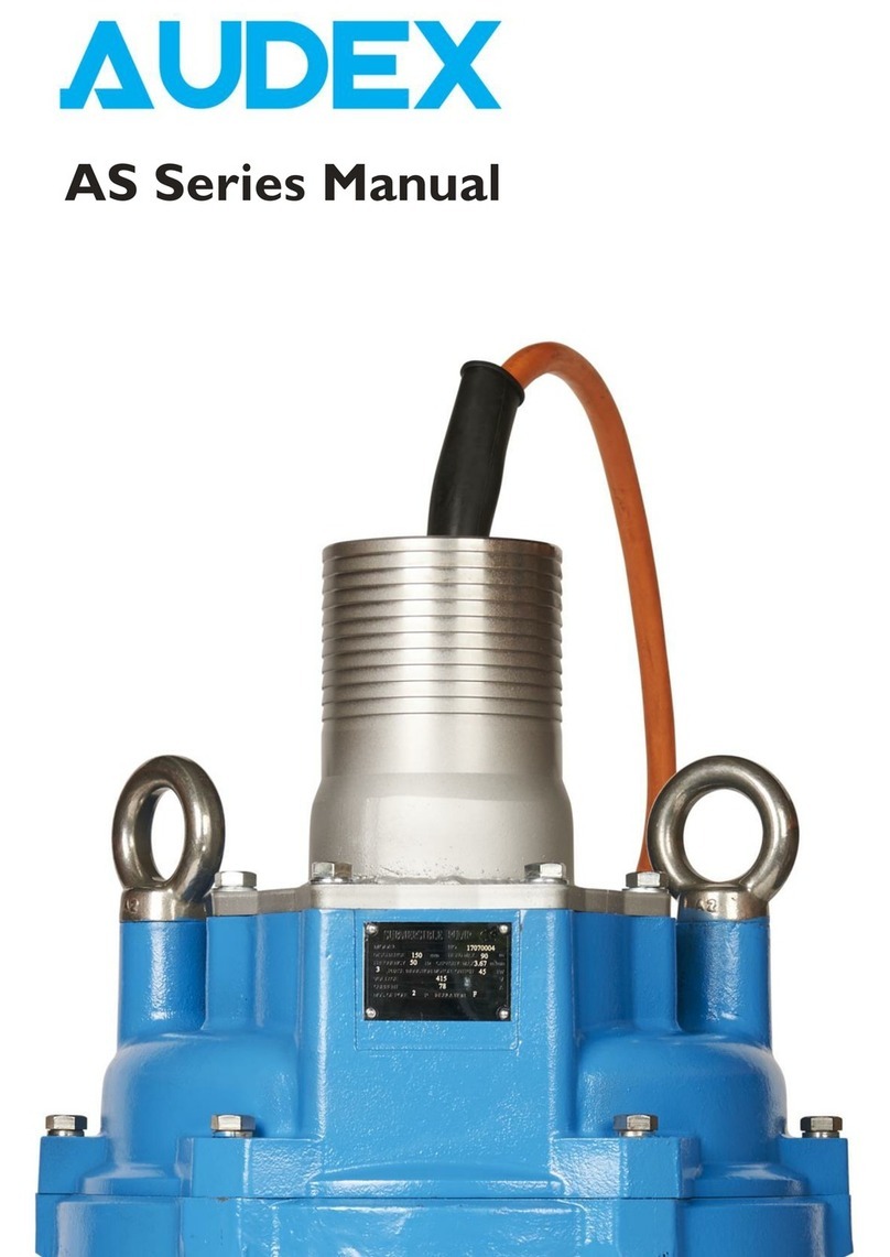
Audex AW Pro Series User manual

AW Pro Series Manual

2
Audex Manual
Contents
Warnings and Safety ……….…….……….……….………………….………….…..……………………
Prior to Use ……………………………………………………………………………………………...
Installation Considerations ……………………………………………………………………………….
Installation Preparation …………………………………………………………………………………...
Installation Electrical …………………………………………….………………………………………...
Installation Testing ………………………………………………………………………………………..
Running ………………………………………………………………………………………….………...
Maintenance Routine ……………………………………………………………………………………..
Maintenance Parts Diagrams ……………………………………………………………………………...
Maintenance Disassembly AW 1.5 - 3.7kW …………..………………………………………………….
Maintenance Assembly AW 1.5 - 3.7kW …………..……………………………………………………..
Storage ……………………………………………………………………………………………………
Running …………………………………………………………………………………………..………..
Data Tables ……………………………………………………………………………………………….
03
07
08
09
10
12
13
14
15
27
32
37
38
39

3
Warnings & Safety
Warnings & Safety
Read this manual carefully before installing and using your Audex AW Pro pump. Improper use of this
product can cause personal injury and damage to property and may void the warranty.
Please retain this manual for future reference and keep it readily available at the location of the unit.
It is extremely important that you read and understand the safety messages and regulations carefully
before handling the product.
They are published to help reduce the risk of the following hazards as far as reasonably practicable:
• Personal accidents and health problems, now and in the future
• Damage to the product
• Product malfunction
The operator must be aware of all appropriate safety precautions to prevent physical injury.
Operating, installing, or maintaining the unit in any way that is not covered in this manual could cause
death, serious personal injury, or damage to the equipment. This includes any modification to the
equipment or use of parts not provided. If there is a question regarding the intended use of the
equipment, please contact a representative before proceeding.
This manual clearly identifies accepted methods for disassembling units. These methods must be adhered
to.
Trapped liquid can rapidly expand and result in explosion and injury. Never apply heat to impellers or
their retaining devices to aid in their removal.
Do not change the service application without the approval of an authorized representative.
Always keep the work area for installation, operation and maintenance, clean and tidy.
Pay attention to the risks presented by gas and vapours in the work area.
Avoid all electrical dangers. Pay attention to the risks of electric shock or arc flash hazards.
Always bear in mind the risk of drowning, electrical accidents, and burn injuries.
Never operate a pump unit unless appropriate safety devices are installed.
Electrical connections must be made by certified electricians in compliance with all international, national,
state, and local regulations. For more information about requirements, see sections dealing specifically
with electrical connections, in conjunction with regulations applicable at the location where the
connections are taking place.
Follow all regulations regarding oils and greases used in the operation, storage, and maintenance of your
Audex pump.

4
Warnings & Safety
Installation
For electrical installation recycling requirements, consult your local electricity authority and conform to all
local and national regulations.
Disconnect and lock out electrical power before installing, servicing, or maintaining the unit.
Make sure that the unit is mechanically secure, and that it cannot roll or fall over and injure people or
damage property.
Rinse the unit thoroughly with clean water before working on it.
Rinse the components in water after dismantling.
Check the explosion risk before you weld or use electrical hand tools.
Allow all system and pump components to cool before you handle them.
Make sure that the product and its components have been thoroughly cleaned.
Do not open any vent or drain valves or remove any plugs while the system is pressurised. Make sure that
the pump is isolated from the system and that pressure is relieved before you disassemble the pump,
remove plugs, or disconnect piping.
Worn impeller and/or pump housing can have very sharp edges. Wear protective gloves.
Always perform a trial operation when starting the pump after a reassembly. If the pump was assembled
improperly, it may lead to abnormal operation, electrical error or water damage.
Use the pump dimensional drawing in order to ensure proper installation.
Provide a suitable barrier around the work area, for example, a guard rail.
The supply voltage variation
• Continuous running: max ±5% of the rated voltage.
• Intermittent running: max ±10% of the rated voltage.
To use the pump, the water temperature should be between 0°C and 40°C.
The pump should be used only for pumping water or water-based fluids. The pump should not be used to
pump fluids such as oil or organic solvents.
The pump must never be used to pump explosive liquids and should not be operated in an area where
explosive elements may be present.
The pump must not be used in a partially disassembled state.
Do not use the pump in an area where the water pressure exceeds the values given below, as it may
damage the pump, or cause a short or electrical shock.
If an excessive amount of sediment is drawn into the pump, it may cause the pump to wear, which can
lead to current leakage or electrical error.

5
Warnings & Safety
Make sure that all unused conductors are insulated.
You must ground all electrical equipment. This applies to the pump, all starting and running control
panel/s, and any monitoring equipment. Test the ground lead to verify that it is connected correctly.
If the motor cable is jerked loose by mistake, the ground conductor should be the last conductor to come
loose from its terminal. Make sure that the ground conductor is longer than the phase conductors. This
applies to both ends of the motor cable.
Risk of electrical shock or burn. You must connect an additional ground fault protection device to the
grounded connectors if persons may come into physical contact with the pump or pumped liquids.
As the pump is equipped with automatic level control and internal contactor, there is a risk of sudden
restart.
Do not insert your finger or any object into the pump’s inlet. Doing so may cause injury, and physical
damage.
Do not operate the pump below Continuous running Water Level (C.W.L) as doing so will damage the
pump, causing current leakage and electrical shock.
Personal injury hazard. Troubleshooting a live control panel exposes personnel to hazardous voltages.
Electrical troubleshooting must be done by a qualified electrician. Failure to follow these instructions will
result in serious personal injury, death, and/or property damage.
Always disconnect and lock out power before servicing to prevent unexpected start-up. Failure to do so
could result in death or serious injury.
Warranty
The Audex comprehensive global warranty is included in your sale price.
Applies to Audex pumps purchased from Atlantic Pumps UK or All Pumps Argentina, or an authorized
Intrax distributor.
To keep your Warranty valid, please note:
• This pump has been registered on the Intrax Pump Register
• All wear parts, and normal wear & tear, are excluded from the Warranty
• Inadequate maintenance, or faulty repair by a non-Intrax company invalidates the warranty
• Please use genuine OEM parts manufactured or supplied by an Intrax company
• Please observe the installation and operating instructions
• Specified regular service schedules must be adhered to, and all services logged on the Intrax Pump
Register
• Any changes to the pump location or application to be recorded on the Intrax Pump Register
• The warranty starts from the day of despatch from our premises and lasts for 1 year
• This warranty is always subject to our terms and conditions, available on our website at
www.atlanticpumps.co.uk
• When purchasing pump parts, please provide the product code shown on the nameplate.

6
Warnings & Safety
Environmental
Always keep the operation, storage, and maintenance areas clean to avoid and/or discover oil and other
contaminant leakages etc.
Dispose appropriately of all waste, particularly if any non-biodegradable oils used.
Handle and dispose of the processed liquid in compliance with all applicable environmental regulations.
Clean up all spills in accordance with all applicable safety and environmental procedures.
Report all environmental emissions and leakages to the appropriate authorities.
Recycling Guidelines
Please recycle every worn and/or disused part and/or pump where possible. Local and national guidelines
must be followed. If local recycling facilities are not readily available, please contact your distributor to
obtain guidance.

7
Prior to Use
Prior to Use
1. Inspect the product
a. Ensure that all items on the delivery note or packing list are present, and that no items are
damaged.
b. Unpack the goods and visually ensure that all parts are undamaged. Check that bolts and screws
have not come loose during transit.
c. If any issues are identified do not proceed further and immediately contact your Intrax dealer
from whom you purchased the product, or the nearest representative office. The delivery should
not be accepted or signed for prior to completion of all of the above checks.
2. Check the specification
a. Find the nameplate on the pump and verify that it is the one you have ordered.
b. Ensure that the voltage and frequency specifications match the original specification.
c. If any issues are identified do not proceed further and immediately contact your Intrax dealer
from whom you purchased the product, or the nearest representative office. The delivery should
not be accepted or signed for prior to completion of all of the above checks.
3. Method of starting
a. Ensure that the selected starting method is capable of driving your pump. Please note that
electrical motors are largely inductive, so the current may significantly spike on start-up.
Your pump is DOL (Direct On Line) start so can create a current spike up to approximately 6
times the rated current.
b. Soft starts and inverters cannot be used with AW Pro pumps.

8
Installation Considerations
Installation Considerations
1. Considerations
a. Mounting
i. Audex pumps should be either suspended from provided lifting points or rings, or
suspended by purpose designed clamps around the pump.
ii. Audex pumps should never be stood on the base of a tank where silt or sand could build
up.
iii. Ensure that the cable has no sharp bends, is not pinched, and cannot be drawn into the
pump inlet.
iv. Ensure that the hose or pipework is firmly attached to the pump outlet.
v. The pump should never be suspended by the cable or pipework.
b. Suction requirements
i. All Audex pumps require submersion up to the rated continuous working level as a
minimum. This information is in the data tables later in this manual.
ii. All Audex pumps have a maximum submersion pressure, this information is in the data
tables later in this manual.
iii. The pump strainer / inlet should never be blocked.
iv. The fluid should not contain particles with any dimensions larger than the rated pump
solids passage.
c. Ensure that the pump noise level is below the site / location permittable level.

9
Installation Preparation
Installation Preparation
1. Pre-installation
a. Recommended required install tools
i. AC voltmeter
ii. AC ammeter (non-contact CT type)
iii. Insulation resistance tester
iv. Spanners / wrenches
v. Screwdrivers
vi. Cable preparation tools as appropriate
vii. Electrical panel key

10
Installation Electrical
Installation Electrical
1. Electrical connection
a. Preparation
i. Ensure that the voltage and frequency of the supply match the requirements on the data
plate.
ii. Ensure that all circuit breakers and similar equipment are rated correctly, and set to the
appropriate level where applicable.
iii. Ensure that all cables and wires are of a sufficient specification for the required current
and voltage, and comply with all relevant regulations.
iv. Ensure that the pump cable sheath is completely undamaged. Any cuts or holes which
penetrate the outer sheath or further are not permitted, and the pump should not be used if
any such fault is present. Water can travel down the inside of the outer sheath and into the
motor.
v. If the pump will be running intermittently, ensure that the max start/stops of the pump are
complied with through the appropriate means.
vi. The cable gland on the pump is resin-filled to ensure weathertightness. If the cable is
strained in any direction this may be compromised and therefore the pump should be
returned to the dealer / manufacturer for the cable to be re-set in resin.
b. Connection
i. Ensure that control panel entry holes are suitably protected to prevent cable damage and
isolate accidental cable strain to outside the panel. In most cases this will be an IP rated cable
gland.
ii. Use cable crimps or ferrules where possible to ensure that all strands of each core are
used, remain undamaged, and are protected.
iii. Earth should always be connected to the earth terminal in the panel.
iv. With three phase pumps the three live connections are usually numbered 1 to 3, and most
commonly connected as follows for the correct phase rotation:
1. Normally Brown / Red
2. Normally Black
3. Normally Grey / Gray / Blue

11
Installation Electrical
v. Ensure that all terminals are tightened sufficiently to ensure arcing is not possible due to
loose connections.
vi. All cable bends should not be sharp. The cables have a minimum bending radius which is
available from Audex or your local distributor if in doubt.
vii. The voltage drop in long cables must be taken into account. The pump rated voltage is as
at the pump, not the supply end of the cable. With 20m or less cables, this voltage drop is
usually negligible but if in doubt or if longer cables are used this should be verified. Voltage
tolerance is available from Audex or your local distributor.

12
Installation Testing
Installation Testing
1. Operation –This is a general guide and location specific considerations must be taken into account to
ensure safety.
i. Attach the hose / pipework
ii. Put the pump into the fluid in its final location
iii. Turn the pump on to ensure everything works correctly. Please note that if the pump is turning
in the wrong direction, it will still pump in the same direction but the flow will be reduced
(normally around 60%), and the pump life will be very dramatically shortened.

13
Installation Testing
Running
Your pump will not start unless the float switch / level sensor is submerged.
After turning the pump on it will not start for 60 seconds, which prevents the pump rapidly cutting on and
off when the float switch / level sensor is splashed with water.
If the pump is connected up to run the wrong way, it will not start at all. If the pump has not started after
2 minutes, please swap two of the live connections around in the panel, e.g. L1 –L2 and L2 –L1
If the pump still does not start after a further two minutes, please check that all three phases have power
present, as a missing one will prevent the pump running for five minutes, after which it will check the
presence of each phase again.
If all phases are present, please check the voltage between each phase to ensure it is with normal levels. If
the voltage is too low or high, the pump will not start for five minutes, after which it will check the
incoming voltage again.
If the voltage is also correct, please disconnect the power, and ensure that the pump impeller can turn
freely. If the impeller is jammed, the pump will turn off for five minutes, after which it will try to start
again.
Please note that the cable is connected to a contactor inside the pump, so it is not possible to check the
winding resistance without disassembling the pump.
If the pump still will not start, please contact the dealer from whom you purchased the pump.

14
Maintenance Routine
Maintenance Routine
1. Routine maintenance
a. Oil checks
i. Remove the oil plug and take out a small amount of oil. The oil can be extracted easily by
tilting the pump so that the oil plug faces downward. If the oil appears discoloured or mixed
with water, a likely cause is a defective or worn mechanical seal which means that a full
refurbishment is necessary before the pump next runs.
b. Oil changes
i. Remove the oil plug and drain the oil completely. Pour the specified oil volume (quantity
available in the data tables on page 32) into the oil filter inlet.
ii. Dispose of the drained oil in compliance with the rules and laws of the location where the
maintenance is taking place.
iii. Replace the o-ring which seals the filter plug, and screw the filter plug back into the pump.
c. Power usage
i. Check the power drawn from each phase with the use of a CT type ammeter (clips around
the cable). If this has changed significantly since the pump was installed, or if one phase
has a notably higher or lower current than any of the other phases, stop the pump and speak
to the distributor / manufacturer about the issue.

15
Maintenance Parts Diagrams
Maintenance Parts Diagrams
AW Pro 2-150 TA

16
Maintenance Parts Diagrams I AW Pro 2-150 TA

17
Maintenance Parts Diagrams I AW Pro 2-150 TA
Index Part Q'ty Material
1 Hose Coupling 1 Cast Iron
2 Handle 1 Rubber & Steel
5 Upper Cover 1 Cast Iron
6 Upper Support 1 Cast Iron
7 Bearing House 1 Cast Iron
11 Motor Body 1 Cast Iron
13 Pump Body 1 Cast Iron
14a Impeller 1 High Chrome Alloy
14b Agitator 1 High Chrome Alloy
16 Inlet Plate 1 Ductile Iron
21a Protecting Plate 1 PA66
21b Protecting Cap 1 PA66
22 Seat Assembly 1 PC
25 Strainer 1 Steel
27 Stator 1
28 Rotor 1 Shaft:AISI420SS
31a Bearing 1
31b Bearing 1
34 Mechanical Seal 1 Sic-Sic/Sic-Sic
35 Oil Seal 1
36a O'ring 2 NBR
36b O'ring 2 NBR
36c O'ring 1 NBR
36d O'ring 1 NBR
37a Gasket 1 NBR
37b Gasket 3 NBR
37c Gasket 1 PVC
38 Shaft Sleeve 1 AISI420SS
41a Cable Clampling Band 1 AISI420SS
41b Mechanical Seal Fixing Plate 1
41c Shim 1 AISI304SS
41d Shim 1 ABS
41e Shim 1 ABS
42a Bolt 4 AISI304SS
42b Bolt 4 AISI304SS
42c Screw 2 AISI304SS
42d Bolt 2 AISI304SS
42e Bolt 2 AISI304SS
42f Bolt 4 AISI304SS
42g Screw 1
42h Screw 2
42i Bolt 4 AISI304SS
42J Screw 4
42K Screw 4
42L Screw 3 AISI420SS
42m Screw 2
42n Screw 3
42o Screw 1 AISI304SS
42p Screw 2 AISI304SS
43a Nut 2 AISI304SS
43b Nut 3 AISI304SS
44a Spring Washer 6 AISI304SS
Index Part Q'ty Material
44b Spring Washer 8 AISI304SS
44c Bearing Washer 1
44d Washer 1 AISI304SS
44e Washer 4 AISI304SS
44f Wave Pad 1 65Mn
44g Spring Washer 4
44h Profiled Pad 1 AISI420SS
44i Impeller Washer 1 AISI304SS
44J Spring Washer 1 AISI304SS
44k Washer 6 AISI304SS
44L Washer 1 AISI304SS
45 Key 1 AISI304SS
46a Circlips for Holes 1
46b Circlips for Shaft 1
47 Cable 1
47※Cable Assembly 1
48a Rubber Sleeve 1 NBR
48b Cable Beads 1 NBR
57 Rod 1 AISI304SS
61 Chain 1
62a Connecting Terminal 5
62b Connecting Terminal 5
86 AC Contactor 1
86a Water Level Sensor 1
88 Controller Block 1

18
Maintenance Parts Diagrams I AW Pro 2-220 TA
AW Pro 2-220 TA

19
Maintenance Parts Diagrams I AW Pro 2-220 TA

20
Maintenance Parts Diagrams I AW Pro 2-220 TA
Index Part Q'ty Material
1 Hose Coupling 1 Cast Iron
2 Handle 1 Rubber & Steel
5 Upper Cover 1 Cast Iron
6 Upper Support 1 Cast Iron
7 Bearing House 1 Cast Iron
11 Motor Body 1 Cast Iron
13 Pump Body 1 Cast Iron
14a Impeller 1 High Chrome Alloy
14b Agitator 1 High Chrome Alloy
16 Inlet Plate 1 Ductile Iron
21a Protecting Plate 1 PA66
21b Protecting Cap 1 PA66
22 Seat Assembly 1 PC
25 Strainer 1 Steel
27 Stator 1
28 Rotor 1 Shaft:AISI420SS
31a Bearing 1
31b Bearing 1
34 Mechanical Seal 1 Sic-Sic/Sic-Sic
35 Oil Seal 1
36a O'ring 2 NBR
36b O'ring 2 NBR
36c O'ring 1 NBR
36d O'ring 1 NBR
37a Gasket 1 NBR
37b Gasket 3 NBR
37c Gasket 1 PVC
38 Shaft Sleeve 1 AISI420SS
41a Cable Clampling Band 1 AISI420SS
41b Mechanical Seal Fixing Plate 1
41c Shim 1 AISI304SS
41d Shim 1 ABS
41e Shim 1 ABS
42a Bolt 4 AISI304SS
42b Bolt 4 AISI304SS
42c Screw 2 AISI304SS
42d Bolt 2 AISI304SS
42e Bolt 2 AISI304SS
42f Bolt 4 AISI304SS
42g Screw 1
42h Screw 2
42i Bolt 4 AISI304SS
42J Screw 4
42K Screw 4
42L Screw 3 AISI420SS
42m Screw 2
42n Screw 3
42o Screw 1 AISI304SS
42p Screw 2 AISI304SS
43a Nut 2 AISI304SS
43b Nut 3 AISI304SS
44a Spring Washer 6 AISI304SS
Index Part Q'ty Material
44b Spring Washer 8 AISI304SS
44c Bearing Washer 1
44d Washer 1 AISI304SS
44e Washer 4 AISI304SS
44f Wave Pad 1 65Mn
44g Spring Washer 4
44h Profiled Pad 1 AISI420SS
44i Impeller Washer 1 AISI304SS
44J Spring Washer 1 AISI304SS
44k Washer 6 AISI304SS
44L Washer 1 AISI304SS
45 Key 1 AISI304SS
46a Circlips for Holes 1
46b Circlips for Shaft 1
47 Cable 1
47※Cable Assembly 1
48a Rubber Sleeve 1 NBR
48b Cable Beads 1 NBR
57 Rod 1 AISI304SS
61 Chain 1
62a Connecting Terminal 5
62b Connecting Terminal 5
86 AC Contactor 1
86a Water Level Sensor 1
88 Controller Block 1
This manual suits for next models
4
Table of contents
Other Audex Water Pump manuals
Popular Water Pump manuals by other brands

Forester
Forester FVP-250 instruction manual

DAB
DAB KDN Series Instruction for installation and maintenance

Wilo
Wilo Wilo-E 15/1-5 Installation and operating instructions
PRO STORMER
PRO STORMER BDUP2601 instruction manual

NES
NES NBE Series Operation & maintenance manual

Calpeda
Calpeda MXV-B Series Original operating instructions
