Audi-Cord Corporation TDS Series User manual


www.SteamPoweredRadio.Com
I
I
I
I
I
I
I
I
I
I
I
I
I
I
I
I
I
I
I
Table
of
Contents
TWIN
DECK
"ms"
SERIES
REPRODUCERS
1,0
GENERAL
DESCRIPTION
1.1
Un-Packing
1.2
Models
and
Accessories
2,0
SPECIFICATIONS
3,0
OPERATION
3.1
Getting
the
Most
From
the
Cartridge
System
3.2
Selecting
and
Using
the
Customer
Operating
3.3
Constructing
Output
Pads
3.4
Controls
and
Indicators
3.5
Audio
Connections
3.6
Remote
Control
Connections
3.7
Operator
Periodic
Maintenance
4,0
CIRCUIT
DESCRIPTIONS
Options
4.1
Power
Supply
and
Power
Switching
Circuits
Card
4.2
Twin
Deck
Logic
Circuits
Card
4.3
Program
Amplifier(s)
and
Cue
Circuits
Card
4.4
Output
Circuits
Card
5,0
TRANSPORT
DESCRIPTIONS
5.1
The
Tape
Drive
Systems
5.2
Head
Mountings
and
Tape
Guides
5.3
Cartridge
Sensors
5.4
Cartridge
Guides
and
Hold
Downs
6,0
TRANSPORT
DIAGNOSIS
AND
MAINTENANCE
6.1
Transport
Failure
or
Cartridge
and
Tape
Failure?
6.2
Adjustment
of
Cross-Shaft
Mechanism
6.3
Solenoid
Adjustment
6.4
Motor
Adjustment,
Top
Deck
6.5
Lower
Deck
Stop
Adjustment
6.6
Tape
Guide
and
Head
Height
Adjustment
6.7
Head
Penetration,
Angle
and
Cartridge
Tape
Wrap
7,0
ELECTRICAL
MAINTENANCE
7.1
Adjustment
of
Lower
Deck
Azimuth
and
Pha
se
7.2
Head
Azimuth
and
Phase,
Routine
7.3
Frequency
Response
and
Equalization
7.4
Program
Output
Level(s)
7.5
Cue
Detectors
Gain
(a)
PAGE
1
1
2
3
6
6
7
9
10
11
12
12
14
14
14
16
18
19
19
19
19
20
21
21
22
23
23
23
24
25
26
26
26
28
28
29

www.SteamPoweredRadio.Com
8,0
TROUBLESHOOTING
8.1
Mechanical
Failures
in
the
Tape
Drive
System
8.2
Logic
and
Control
Circuits
8.3
Program
Amplifier
and
Cue
Circuits
8.4
Parts
Identification
and
Ordering
Parts
8.5
Symptoms
and
Possible
Cause
Chart
9,0
CIRCUIT
CARD
SCHEMATICS
AND
PICTORIALS
10,0
INTERCONNECTIONS
(tvOTHER
BOARD)
SCHEMATIC
11,0
WARRANTY
(b)
30
30
31
32
32
33
I
I
I
I
I
I
I
I
I
I
I
I
I
I
I
I
I
I
I

www.SteamPoweredRadio.Com
I
I
I
I
1.0
I
I
I
I
I
I
I
I
I
1.1
I
I
I
I
I
I
AUDI-CORD
CORPORATION
''TDS"
SERIES
TWIN
DECK
REPRODUCERS
GENERAL
DESCRIPTION
The
Audi-Cord
Corporation
TDS
Series
Twin
Deck
Reproducers
represent
a
practical
design
in
multi-deck
tape
cartridge
reproducers
that
are
cost-value
engineered
for
long
and
reliable
service.
We
hope
you
will
be
pleased
in
your
selection
of
these
machines
and
the
service
they
will
provide.
Please
take
a
few
minutes
to
read
and
understand
this
instruction
book
before
placing
the
unit
in
service.
To
do
so
will
undoubtedly
provide
y
ou
with
important
information
from
which
to
realize
the
most
from
your
investment.
The
TDS
Series
contains
the
latest
in
solid
state
components
and
modern
hardware,
designed
into
a
readily
accessable
unit
with
a
minimum
of
discreet
wiring.
The
only
moving
parts
are
the
solenoid
and
the
associated
tape
engaging
mechanism.
The
operator
controls
are
on
the
front
panel
along
with
the
important
annuciator
light
s
arranged
for
ease
of
operation
and
understanding.
The
TDS
Series
is
designed
in
harmony
with
the
1976
NAB
Cartridge
Standards
and
it's
intent;
however
certain
level
and
response
parameter
s
are
s
upplied
to
be
more
consistent
with
the
needs
of
the
U.S.
domestic
market
use.
Th
e s e
parameters
are
readily
alt
e
red
by
the
user
to
the
197
6
NAB
Standard
when
desired,
following
the
instructions
i n
Section
7.0,
Electrical
Maintenance
and
Section
3.3,
Constructing
Output
Pads.
Un-Packing
Please
un-pack
carefully
and
retain
the
shipping
materials
until
a
full
inspection
is
completed.
Before
plugging
the
"TDS"
Series
into
the
proper
power
source
examine
the
equipment
for
shipping
damage
both
exterior
and
interior.
Audi-Cord
Corporation
makes
every
possible
attempt
to
design
the
equipment
and
the
packing
such
that
they
will
arrive
in
safe
condition;
however,
rough
handling
by
the
carrier
can
not
always
be
avoided.
1.
www.SteamPoweredRadio.Com
Examine
each
circuit
card
to
insure
it
has
not
worked
loose
from
its
socket
and
inspect
heavy
members
such
as
the
transformers
to
insure
they
have
not
been
broken
loose
or
shifted
on
their
mountings.
If
damage
has
occurred,
please
notify
Audi-Cord
first
for
advise
on
claims
so
that
we
may
avoid
un-necessary
delay
to
the
repair
and
your
use
of
the
equipment.
1.2
MODELS
AND
ACCESSORIES
The
TDS
Series
Twin
Deck
Reproducer
is
available
in
two
standard
models.
MODEL
TDS-1
-
Monophonic
with
3
NAB
Cue
Tones
MODEL
TDS-6
-
Stereophonic
with
3
NAB
Cue
Tones
other
models
are
available
only
on
special
quantity
orders
and
factory
quotation.
An
accessory
rack
mounting
shelf,
part
no.
502-0046
is
available
for
mounting
up
to
two
(2)
units
side
by
side
in
a
rack
conforming
to
RMA
standards.
2.
I
I
I
I
I
I
I
I
I
I
I
I
I
I
I
I
I
I
I
www.SteamPoweredRadio.Com
I
I
I
I
I
I
I
I
I
I
I
I
I
I
I
I
I
I
I
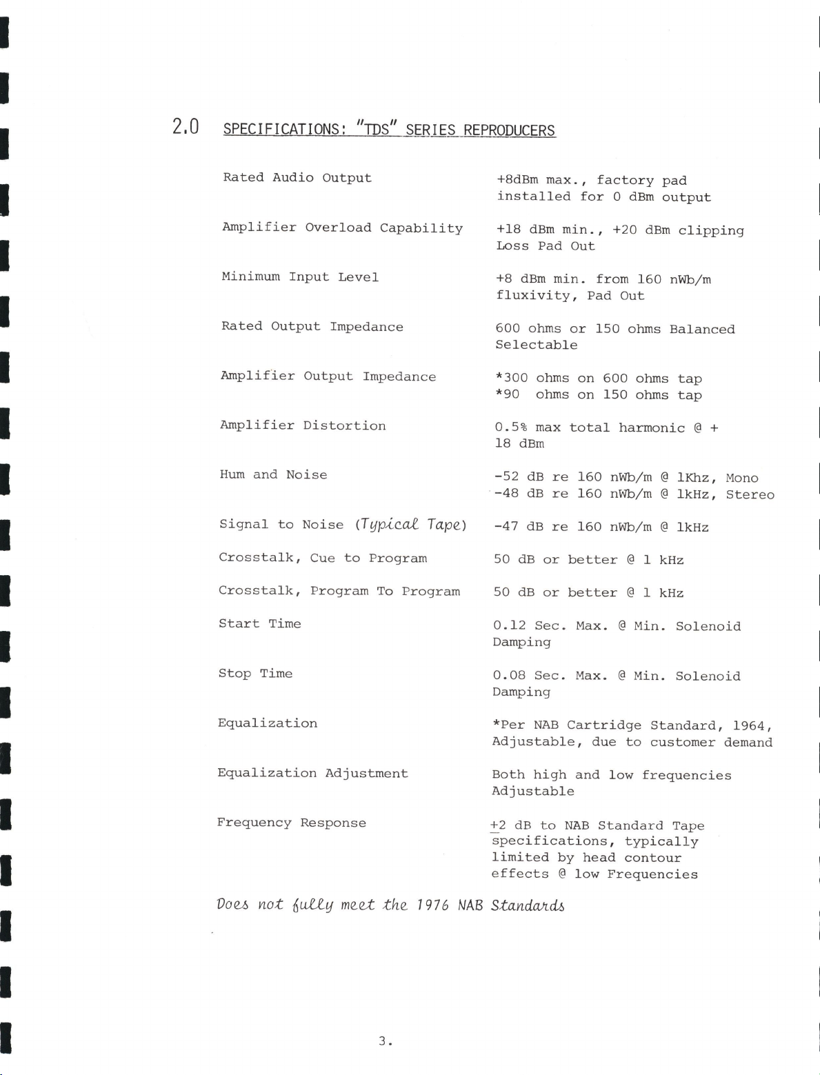
2.0
SPECIFICATIONS:
"ms"
SERIES
REPRODUCERS
Rated
Audio
Output
Amplifier
Overload
Capability
Minimum
Input
Level
Rated
Output
Impedance
Amplifier
Output
Impedance
Amplifier
Distortion
Hum
and
Noise
Signal
to
Noise
(Typi~al.
Tape)
Crosstalk,
Cue
to
Program
Crosstalk,
Program
To
Program
Start
Time
Stop
Time
Equalization
Equalization
Adjustment
Frequency
Response
+8dBm
max.
,
factory
pad
installed
for
O
dBm
ou
t
pu
t
+18
dBm
min.,
+20
dBm
c l
ipping
Loss
Pad
Out
+8
dBm
min.
fr
om
160
nWb/m
fluxivity
,
Pad
Out
600
ohms
or
150
ohms
Balanced
Selectable
*
300
ohms
on
600
ohms
tap
*90
ohms
on
150
ohms
tap
0.5%
max
total
harmonic@+
18
dBm
-52
dB
re
160
nWb/m @
lKhz,
Mono
-48
dB
re
160
nWb/m @
lkHz,
Stereo
-47
dB
re
160
nWb/m @
lkHz
50
dB
or
better
@ 1 kHz
50
dB
or
better
@ 1 kHz
0.12
Sec.
Max.
@
Min.
Solenoid
Damping
0.08
Sec.
Max.
@
Min.
Solenoid
Damping
*Per
NAB
Cartridge
Standard,
1964,
Adjustable,
due
to
customer
demand
Both
high
and
low
frequencies
Adjustable
+2 dB
to
NAB
Standard
Tape
specificat
i
ons
,
typically
limite
d
by
head
contour
effects@
low
Frequencies
Voe.-o
not
6uLe.y
meet
the
19
76
NAB S
tandCVtd..6
3 .
www.SteamPoweredRadio.Com
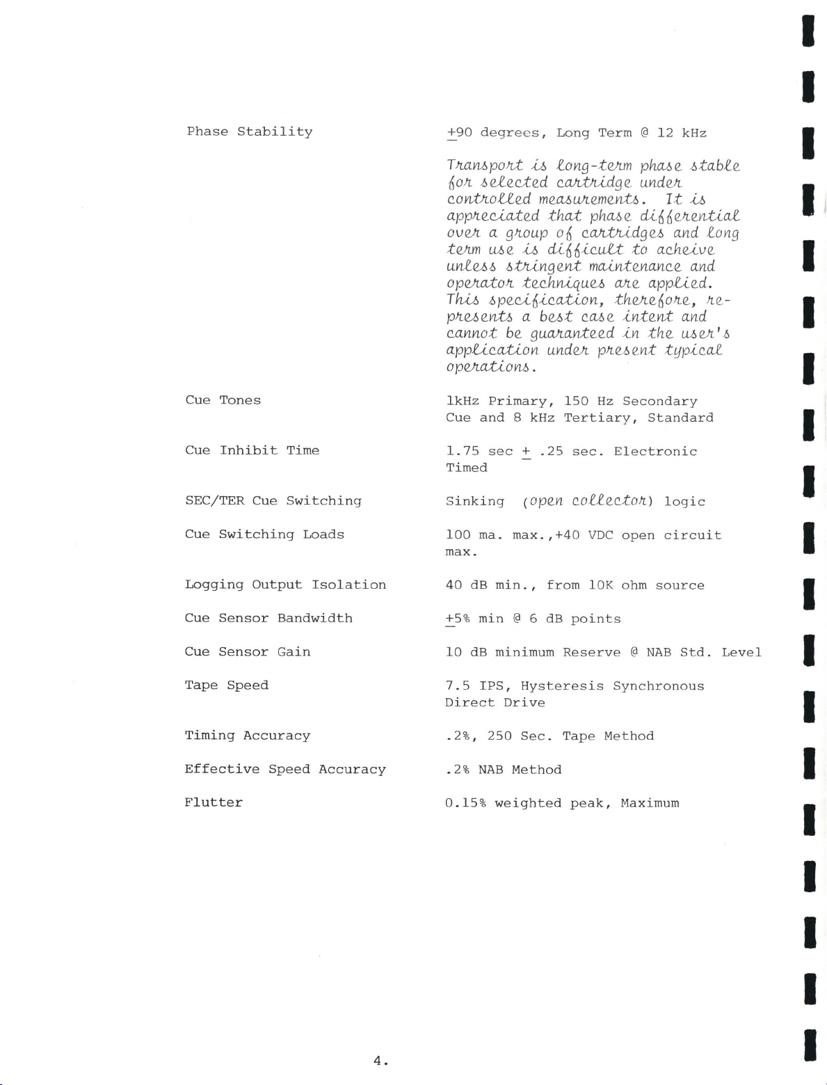
Phase
Stability
Cue
Tones
Cue
Inhibit
Time
SEC/TER
Cue
Switching
Cue
Switching
Loads
Logging
Output
Isolation
Cue
Sensor
Bandwidth
Cue
Sensor
Gain
Tape
Speed
Timing
Accuracy
Effective
Speed
Accuracy
Flutter
4.
~90
de
gr
ee
s,
Long
Term
@
12
kHz
TJtaMpold
,i,.f.,
fong-teAm ph.Me
.6tabf
e
6otr..
.6efec.ted
c.M.;tJu,dg
e. undeJt
c.ontltoUed
meMUJtemen;t/2.
It
,i,.f.,
applteuated
th.at
phMe
cUnneAentiaf
oveA
a
g1toup
06
cM.;tJu,dge
.6
and
long
teAm
Me
,i,.f.,
di66,i.,c.uU
to
ac.h.uve
unfu.6
.6:tlungent
maint
enanc.e and
opeAatoJt
tec.h.Mquu
Me
applied.
Th.,i,.f.,
.6peu6ication,
th.eAe6otr..e,
1t
e.-
p1tuent.6 a
but
cM
e
intent
and
c.annot be
guManteed
in
th.e
MeA
'.6
appuc.ation
undVi. plte.M.
nt
typical
o
peAatio
M •
lkHz
Primary,
150
Hz
Secondary
Cue
and
8 kHz
Tertiary,
Standard
1.75
sec+
.25
sec.
Electronic
Timed
Sinking
(Open
cofiec.toJt)
logic
100
ma.
max.,+40
VDC
open
circuit
max.
40
dB
min.,
from
l0K
ohm
source
+5
%
min@
6 dB
points
10
dB
minimum
Reserve@
NAB
Std.
Level
7.5
IPS,
Hysteresis
Synchronous
Direct
Drive
.2%,
250
Sec.
Tape
Method
.2%
NAB
Method
0.15%
weighted
peak,
Maximum
I
I
I
I
I
I
I
I
I
I
I
I
I
I
I
I
I
I
I

www.SteamPoweredRadio.Com
I
I
I
I
I
I
I
I
I
I
I
I
I
I
I
I
I
I
I
Remote
Control
(a.1.1_
inpUM
aJte.
g1r.ound
-6igna.1.1_e,d)
Cartridge
Capability
Max.
Temp.
Rise
Recommended
Max.
Ambient
Power
Requirements
Dimensions
Weight
5.
15
Pins,
permanently
wired
for:
Start
Stop
Run Lamp
Ready
Lamp
Secondary
Cut
Out
Tertiary
Cue
Out
Gnd
(ChaMi-6)
+24
DC
Logging
Cue
Output
NAB
AA
and
BB
sizes
20
C.
Max.
above
25
C
ambient
40
C
max.
117
volts,
60
Hz,
60
VA
max.
(117
vo-lto,
50
Hz,
on
-6pe.ual
01r.de.1r.>
8!:;"W
x
7!:;"H
x
13~"L
26
lbs.
www.SteamPoweredRadio.Com
I
I
I
I
I
I
I
I
I
I
I
I
I
I
I
I
I
I
I
3,0
OPERATION
3.1
GETTING
THE
MOST
FROM
THE
CARTRIDGE
SYSTEM
It
is
Audi-Cord's
desire
that
every
owner
of
the
"TDS"
Series
Reproducer
obtain
long
and
satisfactory
service
from
the
equipment;
however,
since
the
"TDS"
Series
is
manufactured
to
accommodate
a
wide
variety
of
cartridges
from
several
manufacturers',
it
is
often
true
that
optimum
performance
is
the
result
of
the
users
knowledge
of
the
differences
in
these
cartridges
and
their
best
applications.
If
these
factors
are
well
known,
the
mechanical
fit
of
the
machine
and
the
cartridge
can
often
be
optimized
by
the
skilled
technician
for
best
performance.
Characteristics
which
most
often
influence
performance
of
a
given
cartridge
in
any
machine
are
as
follows:
1.
The
mechanical
fit
of
the
cartridge
to
the
heads
and
the
keyhole
opening.
2.
The
pressure
pad
design
adequacy
and
fit
to
the
heads
as
well
as
interference
to
the
tape
guides.
In
erase/record
applications
for
instance
only
a
few
types
will
adequately
wrap
these
off
center
head
designs.
3.
The
friction
loss
of
the
cartridge
and
tape
and
its'
pulling
tension.
Unlimited
tension
cannot
be
handled
by
the
transport
since
the
capstan
and
roller
surface
engagement
area
is
limited
in
the
inherent
design.
Tension
typically
increases
significantly
with
longer
time
loads
and
in
wear
life.
4.
Contamination
of
the
head
surfaces
if
poor
tape
and
lubricant
is
encountered.
5.
The
internal
quality
contro
l
and
maintenance
routines.
The
above
ch
aracteri
stics
are
all
important
if
failure
of
the
system
is
to
be
avoided.
It
is
unfortunately
true
that
all
cartridges
are
not
the
same
in
design
and,
it
is
virtually
impossible
to
produce
a
cartridge
transport
that
performs
perfec
tly
with
all
the
types;
therefore,
the
user
must
se
lect
the
cartridge
and
tape
best
suited
to
his
needs
and
then
make
such
minor
adjustments
to
the
transport
as
necessary
to
obtain
optimum
performance.
6.

www.SteamPoweredRadio.Com
3.2
Our
Service
Department
will
provide
assistance
when
needed
and
excellent
general
information
is
to
be
found
in
our
Users'
manual
and
the
occasional
updates
that
have
been
issued.
SELECTING
AND
USING
THE
CUSTOMER
OPERATING OPTIONS
The
"TDS"
Series
reproducers
are
equipped
with
a
Replay
Reminder
and
Lockout
System
for
each
deck
and
an
automatic
Motor
Shut
Down
feature
when
both
decks
have
played.
The
customer
selects
how
he
uses
these
features
to
suit
the
needs
of
his
own
operation.
REPLAY
REMINDER
and
LOCKOUT
SYSTEMS-
This
feature
is
valuable
in
line
operations
to
prevent
double
airing
of
carts
that
have
been
previously
played.
The
feature
is
selected
by
switch
Sl,
located
on
the
top
of
the
Twin
Play
Control
Logic
Card
151-68.
Select
this
feature
to
turn
on
the
"Played"
lamp
and
remove
the
"Ready"
status
and
it's
lamp
by
setting
Sections
A
and
B
of
switch
Sl
to
the
"on"
position
for
the
lower
deck
and
sections
C
and
D
of
switch
Sl
to
the
"On"
position
for
the
upper
deck.
If
it
is
desired
to
turn
on
the
"Played"
lamp
only
and
not
remove
the
"Ready"
state,
turn
on
section
A
of
switch
Sl
for
the
lower
deck
and
section
C
for
the
upper
deck,
leaving
sections
Band
Din
the
"off"
position.
The
TDS
reproducer
is
factory
wired
to
allow
reset
of
the
Replay
Reminder
by
either
removing
the
appropriate
cartridge
or
by
pushing
the
"Stop"
pushbutton
of
the
associated
deck.
If
it
is
desired
to
exclude
the
"reset"
by
STOP
pushbutton
feature,
clip
the
buss
link
at
the
top
of
the
card
for
either
or
both
decks.
This
link
is
located
on
the
R.H.
side
(parts
facing)
for
the
top
deck
and
on
the
L.H.
side
for
the
bottom
deck.
MOTOR
SHUTDOWN
FEATURE-
This
feature
is
electrically
designed
to
follow
the
use
of
the
"READY"
status
of
either
deck
with
the
Replay
Lock-out.
If
both
decks
have
been
played
and
therefore
may
be
idle
for
some
period,
the
motor
is
turned
off
to
conserve
energy
and
heat
in
the
machine.
7.
I
I
I
I
I
I
I
I
I
I
I
I
I
I
I
I
I
I
I
www.SteamPoweredRadio.Com
I
I
I
I
I
I
I
I
I
I
I
I
I
I
I
I
I
I
I
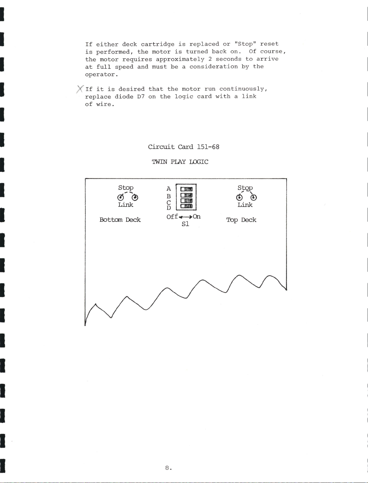
If
either
deck
cartridge
is
replaced
or
"Stop"
reset
is
performed,
the
motor
is
turned
back
on.
Of
course,
the
motor
requires
approximately
2
seconds
to
arrive
at
full
speed
and
must
be
a
consideration
by
the
operator.
If
it
is
desired
that
the
motor
run
continuously,
replace
diode
D7
on
the
logic
card
with
a
link
of
wire.
Stop
~--<?)
Link
Bottom Deck
Circuit
card
151-68
'IWIN
PIAY
ux;rc
B
CHilll
Al
C
DIDII
D
ODDI
Off..-+On
Sl
8.
StQP
, '
@ ©
Link
Top Deck
www.SteamPoweredRadio.Com
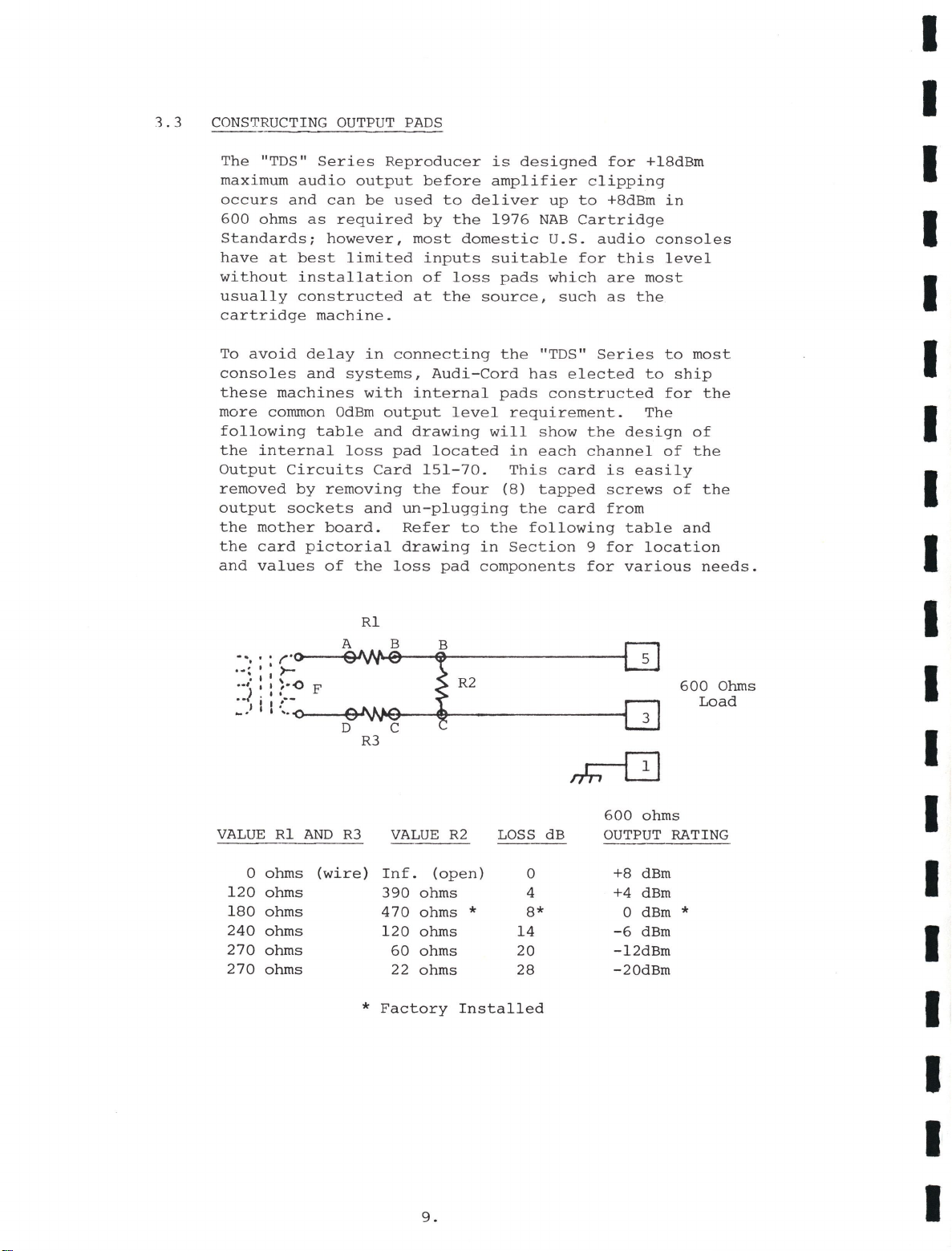
1.3
CONSTRUCTING
OUTPUT
PADS
The
"TDS"
Series
Reproducer
is
designed
for
+18dBm
maximum
audio
output
before
amplifier
clipping
occurs
and
can
be
used
to
deliver
up
to
+8dBm
in
600
ohms
as
required
by
the
1976
NAB
Cartridge
Standards;
however,
most
domestic
U.S.
audio
consoles
have
at
best
limited
inputs
suitable
for
this
level
without
installation
of
loss
pads
which
are
most
usually
constructed
at
the
source,
such
as
the
cartridge
machine.
To
avoid
delay
in
connecting
the
"TDS"
Series
to
most
consoles
and
systems,
Audi-Cord
has
elected
to
ship
these
machines
with
internal
pads
constructed
for
the
more
common
OdBm
output
level
requirement.
The
following
table
and
drawing
will
show
the
design
of
the
internal
loss
pad
located
in
each
channel
of
the
Output
Circuits
Card
151-70.
This
card
is
easily
removed
by
removing
the
four
(8)
tapped
screws
of
the
output
sockets
and
un-plugging
the
card
from
the
mother
board.
Refer
to
the
following
table
and
the
card
pictorial
drawing
in
Section
9
for
location
and
values
of
the
loss
pad
components
for
various
needs.
Rl
VALUE
Rl
AND
R3
VALUE
R2
LOSS dB
0
ohms
(wire)
Inf.
(open)
0
120
ohms
390
ohms
4
180
ohms
470
ohms*
8*
240
ohms
120
ohms
14
270
ohms
60
ohms
20
270
ohms
22
ohms
28
*
Factory
Installed
9.
600
Ohms
Load
600
ohms
OUTPUT
RATING
+8
dBm
+4
dBm
0
dBm*
-6
dBm
-12dBm
-20dBm
I
I
I
I
I
I
I
I
I
I
I
I
I
I
I
I
I
I
I

www.SteamPoweredRadio.Com
I
I
I
I
I
I
I
I
I
I
I
I
I
I
I
I
I
I
I
3.4
CONTROLS
AND
INDICATORS
The
operator
controls
and
indicators
for
the
TDS
Series
reproducers
consist
of
two
sets,
conveniently
grouped
for
operator
identification
of
the
deck
with
which
they
are
associated.
Each
group
contains
an
arrow
symbol
painting
to
the
deck
which
they
operate
with.
The
.
function
of
each
control
or
indicator
without
reference
to
the
deck
used
are
as
follows:
POWER
LIGHT
READY
LIGHT
STOP
PUSHBUTTON
Indicates
that
the
machine
is
on
and
that
the
+24
DC
power
is
present.
Indicates
that
a
cartridge
has
been
properly
installed
and
is
ready
to
play.
(this
lamp
is
part
of
the
STOP
pushbutton.)
Stops
the
transport
and/or
resets
the
REPLAY
reminder
when
this
option
is
selected.
(Remember
that
manual
stop
of
a
cartridge
leaves
it
in
an
un-cued
state
and,
the
cart
should
be
advanced
to
cue
befor
E:_
removalJ
RUN
LIGHT
Indicates
that
the
transport
is
in
the
run
mode
and
playing.
START
PUSHBUTTON
Places
the
transport
in
the
run
mode.
PLAYED
LITE
Indicates
that
the
cartridge
in
place
has
received
the
Primary
Cue
Tone
and
has
been
played.
TER
LITE
SEC
LITE
Indicates
when
the
TER
cue
tone
is
being
received.
Indicates
when
the
SEC
cue
tone
is
being
received.
10.
www.SteamPoweredRadio.Com
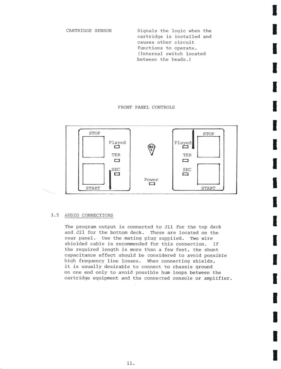
CARTRIDGE SENSOR
Signals
the
logic
when
the
cartridge
is
installed
and
causes
other
circuit
functions
to
operate.
(Internal
switch
located
between
the
heads.)
FRONT
PANEL
CONTROLS
STOP STOP
□
Played
fl
CJ
TER
Played
□
c:J
TER
□
Cl
□
SEC
START
ICJ
Power
CJ
SEC
□
CJ
START
3.5
AUDIO
CONNECTIONS
The
program
output
is
connected
to
Jll
for
the
top
deck
and
J21
for
the
bottom
deck.
These
are
located
on
the
rear
panel.
Use
the
mating
plug
supplied.
Two
wire
shielded
cable
is
recommended
for
this
connection.
If
the
required
length
is
more
than
a
few
feet,
the
shunt
capacitance
effect
should
be
considered
to
avoid
possible
high
frequency
line
losses.
When
connecting
shields,
it
is
usually
desirable
to
connect
to
chassis
ground
on
one
end
only
to
avoid
possible
hum
loops
between
the
cartridge
equipment
and
the
connected
console
or
amplifier.
11.
I
I
I
I
I
I
I
I
I
I
I
I
I
I
I
I
I
I
I

www.SteamPoweredRadio.Com
I
I
I
I
I
I
I
I
I
I
I
I
I
I
I
I
I
I
I
3.6
3.7
The
Connecting
diagram
is
as
follows:
(
+)
GJ
GJ
(
+)
L.
Channel
(-)
G G
(-)
(Mono)
(G)
G
Q]
(G)
REMOTE
CONTROL
CONNECTIONS
R.
Channel
(Stereo)
The
12
pin
remote
control
connectors~2
fort~
top
_
deck
and
J22
for
the
bottom
deck
are
factory
connected
for
the
lb
normally
required
outputs.
The
typical
remote
control
connections
are
as
indicated
in
the
pin
diagram
below.
TER
LOAD
(Sources)
OPERATOR
PERIODIC
MAINTENANCE
LOAD
I
I
L:i:•NG
OUT
The
operator
is
often
charged
with,
or
may
find
it
necessary
to
perform
periodic
cleaning
maintenance
and
other
inspection
to
insure
proper
operation
of
tape
cartridge
machines.
These
maintenance
routines
may
be
daily
or
weekly
depending
upon
the
amount
of
use.
12.
www.SteamPoweredRadio.Com
These
typical
maintenance
functions
are
as
follows:
CLEAN
HEADS, PRESSURE ROLLER
and
CAPSTAN SURFACES-
These
cleaning
functions
are
quality
is
to
be
achieved.
frequency
losses
in
replay
very
important
if
good
Dirt
on
heads
can
cause
or
recording
due
to
tape
air
high
spacing
from
the
head
gaps
and,
under
worst
cases
cause
total
loss
of
audio
or
the
cue
functions.
Lubricant
build
up
on
the
pressure
roller
surface
or
the
capstan
surface
seriously
degrades
pulling
capability
due
to
loss
of
contact
friction
on
these
driving
surfaces
and
under
worst
cases
will
cause
serious
"wow"
or
slip
of
the
tape.
Clean
these
surfaces
with
denatured
alcohol
or
isopropol
alcohol
solvents,
readily
available
at
most
hardware
stores,
by
saturating
and
wringing
dry
a
soft
cloth
or
swab
to
avoid
dripping
of
solvent
into
the
motor
bearing,
etc.
Do
not
use
solvents
such
a
Xyolene
or
Kerosene
since
these
seriously
degrade
rubber
parts.
INSPECT CARTRIDGE
and
TAPE FOR PROPER
OPERATION-These
inspections,
especially
before
re-recording
can
save
the
failure
later
on.
Do
not
attempt
to
record
tape
which
is
slick
on
either
the
oxide
or
the
lubricant
(rear)
surface.
Slick
oxide
surface
usually
means
that
much
of
the
oxid
e
is
missing
and
proper
recorded
levels
cannot
be
achieved
without
serious
distortion
and
loss
of
high
frequency
material.
The
cue
tones
especially
will
usually
be
weak
and
may
not
function
properly.
Loss
of
lubricant
means
that
pulling
tension
has
seriously
increased
and
will
soon
cause
"slip"
in
the
playing
sound.
It
is
almost
certain
that
short
life
will
be
experienced
before
breakage
of
the
tape
occurs.
Proper
operation
of
cartridges
are
normally
detected
during
daily
use.
The
careful
operator
may
observe
potential
recurring
failures
and
avoid
their
occurance.
Periodic
audio
drop-out
for
instance
may
relate
to
a
badly
deformed
pressure
pad
or
increasing
tension
which
may
overcome
the
pressure
pad
conformity.
Erroneous
cues
can
indicate
"pops"
on
the
cue
channel
which
cause
false
tripping
or
stop
of
the
drive
system.
Failures
of
these
types
should
result
in
setting
aside
the
cartridge
for
further
off
air
testing
to
determine
if
they
should
be
used
or,
if
machine
maintenance
is
required.
13.
I
I
I
I
I
I
I
I
I
I
I
I
I
I
I
I
I
I
I

www.SteamPoweredRadio.Com
I
I
I
I
I
I
I
I
I
I
I
I
I
I
I
I
I
I
I
4,0
CIRCUIT
DESCRIPTIONS
4.1
POWER
SUPPLY
AND
SWITCHING CIRCUITS
CARD
4.2
The
D.C.
pow
er
supplies,
solenoid
switching
circuits
and
the
motor
switching
circuit
are
located
on
the
plug-in
circuit
card
151-69.
Refer
to
the
schematic
in
Section
9.
Diodes
Dl
and
D2
provide
rectified
DC
from
the
center
tapped
winding
of
the
power
transformer
to
capacitor
Cl
for
smoothing.
This
approximately
33
volts
DC
is
fed
to
edge
connection
pin
18
and,
to
the
input
of
the
24
volt
regulator
Ul
for
further
filtering
and
use
in
the
machine
control
circuits.
It
is
also
fed
thru
diodes
D3
and
D4
and
resistors
Rl
and
R2
to
the
solenoid
switching
circuits
explained
later.
Diodes
D6
and
D7
in
a
similar
manner
supply
approximately
18
volts
DC
to
the
input
of
the
12
volt
regulator
U2.
This
regulated
and
filtered
12
volts
DC
is
used
for
the
audio
and
logic
control
circuits.
Transistor
Ql
is
a
power
switch
for
the
solenoid
of
the
upper
deck.
Capacitor
CS
is
charged
to
the
33
volts
DC
supply
when
the
machine
is
idle
and
serves
as
a
"boost"
voltage
source
to
accelerate
the
solenoid
when
Ql
is
first
turned
on
by
the
logic
driver.
Diodes
Dl3
and
Dl5
serve
as
transient
suppressors
for
the
solenoid
inductance
and
diode
Dl4
acts
as
an
isolation
diode
for
the
Run
Lamps.
The
circuits
for
the
lower
deck
is
identical
and
are
provided
by
transistor
Q2
and
the
associated
parts.
Integrated
circuit
U3
(light
activated
SCR)
along
with
diodes
D9
thru
Dl2
serve
as
an
isolated
AC
switch
to
turn
the
capstan
motor
on
or
off
from
the
logic
signal
"MOTOR=0".
Diodes
DS
and
D8
protect
their
respective
voltage
regulators
from
accidental
reverse
voltage
failure.
TWIN
DECK
LOGIC
CIRCUITS
CARD
The
logic
to
control
playing
functions
of
both
decks
are
located
on
the
plug
in
circuit
card
151-68.
Refer
to
the
schematic
in
Section
9.
14
.

www.SteamPoweredRadio.Com
The
schematic
is
formatted
such
that
most
input
signals
are
shown
on
the
left
side
with
output
decision
signals
exiting
on
the
right
side.
Internal
word
statements
define
some
of
the
major
signal
paths
for
assistance
in
understanding.
The
logic
1
state
is
at
or
near
+12DC
volts
and
logic
0
state
is
at
or
near
chassis
ground
potential.
Two
identical
sections
of
logic
are
contained
on
this
card
for
the
most
common
functions,
while
one
output,
Motor=0
is
derived
in
OR
format.
This
purpose
will
be
described
later.
Integrated
circuits
Ul,
U2
and
U3
are
exclusive
to
Deck
#1
(the
upper
deck),
while
U6,
U7
and
UB
are
their
counterparts
exclusive
to
Deck
#2.
One
half
of
US
and
U9
as
well
as
sections
of
U4
are
common
to
both
decks.
The
following
description
will
be
of
Deck
#1
circuits
only
and
is
the
same
functionally
except
for
part
numbers
in
the
case
of
Deck
2
circuits.
Integrated
circuit
U2
is
a
two
section
SET-RESET
latch.
Section
2
is
the
START-STOP
latch,
while
section
1
is
the
Replay
Reminder
latch.
Section
3
of
Ul
is
the
steering
section
for
the
START
signal.
When
Ready=0
and
Start=0
are
present,
pin
10
is
at
logic
1,
setting
the
RUN
latch
to
ON.
Pin
13
of
Ul
produces
a
RUN=
J.
logic
for
use
in
the
cue
and
program
control
circuits,
while
pin
12
thru
section
4
of
Ul
and
transistor
Ql
produces
the
RUN
DRIVE
signal
used
in
the
solenoid
switching
circuit.
U3
integrates
the
three
signals
STOP
(P.B.),
CUE=l
and
CART.
SW
(in=l)
for
decision
of
the
rest
of
the
circuits.
When
the
CART
SW.
is
at
logic
1
and
INHIBIT=l
(not
inhibited),
either
CUE=l
or
STOP
P.B.=0
causes
U3
pin
6
to
produce
a
stop=l
signal
to
reset
U2.
When
CUE=l,
pin
9
of
U3
causes
the
REPLAY
REMINDER
latch,
pin
6
to
turn
on,
creating
the
PLAYED=l
signal
and
turning
on
the
PLAYED
light
via
transistor
Q2.
In
the
lower
deck
(#2)
the
PLAYED
light
is
via
section
1
of
Ul0.
15.
I
I
I
I
I
I
I
I
I
I
I
I
I
I
I
I
I
I
I
www.SteamPoweredRadio.Com
I
I
I
I
I
I
I
I
I
I
I
I
I
I
I
I
I
I
I
The
PLAYED=l
signal
is
coupled
via
switch
1
section
D
to
pin
1
of
Ul.
This
signal
produces
an
output
logic
1
at
pin
3,
removing
the
READY=O
signal.
In
a
similar
manner,
if
a
cartridge
is
not
in
place
(CART
SW=O),
pin
8
of
U4
turns
off
the
READY=O
via
pin
2
of
Ul.
The
REPLAY
REMINDER
latch,
U2
pin
4
is
reset
each
time
the
cartridge
is
removed
or,
if
the
link
between
pin
5
and
pins
11
and
12
of
U3
is
in
place,
this
reset
occurs
by
the
STOP
pushbutton.
Pin
10
of
Section
2,
US
sees
the
RUN=l
signal
each
time
the
machine
is
started.
This
action
triggers
the
output
at
pin
12
of
US
to
INHIBIT=O.
The
duration
of
this
inhibit
is
determined
by
C9
and
R21
and
is
factory
set
at
approximately
1.75
seconds.
Integrated
circuit
U9
pin
1
and
pin
2
are
connected
to
the
logic
of
each
deck.
These
signals
are
identified
as
MOTOR
l=l
and
MOTOR
2=1.
If
either
deck
remains
in
the
READY
state
the
output
of
U9
pin
3
is
at
MOTOR=O,
turning
the
motor
on.
If
both
READY
states
are
missing
such
as
the
cartridges
out
or
both
decks
are
PLAYED,
the
motor
is
turned
off
to
conserve
power
and
heat.
If
it
is
required
that
the
motor
run
continuously,
replace
diode
D7
with
a
link
of
wire.
4.3
PROGRAM
AMPLIFIER(S)
and
CUE
CIRCUITS
CARD
The
program
and
cue
circuits
are
both
contained
on
a
single
circuit
card
151-67.
There
are
two
identical
cards,
one
for
each
associated
deck.
The
card
located
on
the
extreme
L.
side
is
for
the
top
deck
(Deck
#1)
while
the
second
card
from
the
L.
side
is
for
the
lower
deck
(Deck
#2).
Refer
to
the
schematic
in
Section
9.
PROGRAM
AMPLIFIER(S)
SECTION-
The
play
head(s)
are
connected
via
cables
and
3
pin
connectors
on
the
rear
of
the
card
nearest
the
deck
plate.
Stereo
models
have
2
connectors
in
this
location.
The
top
connector
is
L.
channel
and
the
bottom
is
R.
channel.
Observe
the
identification
dots
on
the
cable
when
plugging
in
these
cables
to
avoid
interchange
of
the
channels.
I.C.
Ul
is
a
low
noise
packaged
pre-amplifier
with
approximately
40dB
of
mid
range
gain.
Two
frequency
equalizers
are
provided
in
the
gain
loops.
For
L.
Channel
of
stereo
or
mono
models,
R8
is
the
adjustable
low
frequency
equalizer
of
limited
range
in
th
e
inverting
feedback
section.
CS
sets
the
crossover
frequency
for
16.
www.SteamPoweredRadio.Com
RB,
which
is
adjusted
typically
at
S0Hz
to
improve
the
low
frequency
loss
and
contour
effect
of
the
head
used.
The
base
gain
is
established
by
RS
and
C4
while
the
equalized
portion
is
set
by
R7.
Capacitor
C6
bypasses
the
mid
to
high
frequencies.
R2
is
the
adjustable
portion
of
the
high
frequency
shunt
equalizer,
while
C2
and
R3
establishes
the
crossover
frequency
of
the
equalizer.
Resistor
R4
establishes
the
DC
feedback
bia
s
in
conjunction
with
R6.
Level
control
R9
allows
for
output
level
adjustment.
I.C.
U2
is
a 4
section
FET
analog
control
switch
to
control
turn
off
of
the
audio
during
non-running
periods.
Resistor
R36,
R37
and
R3B
and
Capacitor
Cl6
provide
a
ramp-up
and
ramp-down
time
to
avoid
audio
pops
.
Transistor
Ql
is
a
split
phase
pre-driver
for
the
complimentary
output
amplifier
Q2
and
Q3.
The
output
is
coupled
thru
Cl9
to
the
primary
of
the
line
transformer
located
on
the
Output
Circuit
card.
The
R.
Channel
of
stereo
models
is
identical
to
the
description
of
the
L.
Channel
above
except
for
the
change
in
part
number
designations.
CUE
AMPLIFIER
AND
DETECTORS
The
cue
head
is
connected
via
a 3
pin
connecting
cable
located
on
the
rear
of
the
circuit
card.
Intergrated
circuit
U3
is
configured
in
a
two
stage
equalized
pre-amplifier
with
output
essentially
constant
for
the
3
NAB
cue
tone
flux
levels.
This
output
is
connected
thru
R49
and
C2B
to
section
2
of
I.C.
U4
which
acts
as
the
isolation
amplifier
for
logging
signal
outputs,
used
frequently
in
automation
and
accessory
controllers.
This
output
is
routed
to
pin
10
of
the
remote
sockets
and
is
often
valuable
for
cue
track
monitoring
and
test
functions.
Section
1
of
I.C.
U4
is
configured
as
a
bridged
T
passive
amplifier
tuned
to
the
1
kHz
center
frequency.
This
circuit
is
stable
and
will
require
no
further
tuning.
The
output
is
connected
via
C33
to
transistor
Q7.
This
is
a
zero
bias
A.C.
detector
coupled
thru
R61
to
C34.
These
components
along
with
R60
form
a
time
constant
to
delay
turn
on
of
QB
for
approximately
20
milli-seconds
to
immunize
the
circuit
from
short
transients
and
remove
"clatter".
QB
derives
the
logic
signal
CUE=l
for
automatic
stop
control.
17.
I
I
I
I
I
I
I
I
I
I
I
I
I
I
I
I
I
I
This manual suits for next models
2
Table of contents


