Audia Flight FLS 10 User manual

Owner’s manual
FLS 10
Balanced Stereo Integrated
Amplifier


3
Dear Customer,
Audia Flight congratulates you and thanks you for choosing one of its products to set up your sound
system.
The FLS 10 balanced stereo integrated amplifier has been patiently designed with the intention of be-
ing one of the best equipment available and capable of driving any loudspeaker system on the market
today. This goal has been achived using all the know-how of the brand, the application of the most
powerful techniques and the use of the best components. Its production does not suffer any compro-
mise and it has been made with extreme attention and care.
The FLS 10 is an unrivalled integrated power amplifier on its category where speed, driving capability
and control ability are elements close to perfection and capable of powering any speaker available
on the market. You can be assured of having a device that will serve you and give you many years of
musical enjoyment.
The FLS 10 balanced stereo integrated amplifier is very flexible too; it is possible to install optional
boards including MM/MC phono stage, DAC, analog inputs and more. Please visit our website to see
the latest news about your product.
This manual is intended to advise you and help you to get from your amp the best possible.
Safety instructions
Before you start using your FLS 10 balanced stereo integrated amplifier, please read the operating
instructions and safety precautions outlined below.
1. Always make sure the unit is unplugged before connecting or disconnecting any other device
of the audio system in case of intervention on these devices.
2. Your device comes with a three-wire power cord (AC voltage of 100 - 115 V or 230 - 245V). To
prevent electrical shock, all three wires must be used. If your outlet does not accept the plug type
fitted to the cord, you need an adapter and, if so, make sure it meets the required safety standards
and, above all, establishes a connection to earth. If in doubt about the integrity of your electrical
system call in the assistance of a qualified professional.
3. The use of an extension cord is not recommended for this product. If an extension is required,
ensure its compliance with safety rules and its ability to withstand the intensity of current required
to power your device.
4. Never use flammable or combustible chemicals for cleaning.
5. Do not attempt to open the device, in under no circumstances use it without removing all the
packing materials or elements covering the unit.
6. Do not spill nor spray any liquids directly on the device.
7. Never push objects through openings in the unit.
8. Never remove a fuse.
9. Never replace a fuse with one of size or type than those specified.
10. Never attempt to repair the unit yourself. In case of problems, contact your dealer.
11. Never expose your device to temperatures too high or too low.
12. Do not leave electrical appliances within the reach of children.
13. Do not insert any object into the ventilation slots.

4
Transport and unpacking
Because of the significant weight of the unit, the assistance of one or two other people, for moving and
placing it, is highly recommended. Do not turn the package upside down. Before opening the package,
place it near the planned installing location.
To open wooden package, remove all the 16 screws.
The package contains the FLS 10 balanced stereo integrated amplifier, a detailed instruction manual,
a power cord and a remote control with screwdriver.
We recommend you to keep packaging for future shipping. If unit will be packed again, be sure to
locate again all internal packing components. Audia Flight will be not considered responsible for any
accident or damage to things or persons, resulting from future poor packaging.
Location
Choose a location that can support the heavy weight of your device. In order to dissipate heat, let
free a space of at least 10 cm around the amplifier, so that ventilation could happen naturally. Move
it away from sources of heat or vibration, do not expose it to direct sunlight. Do not locate the unit
close to electroluminescent light sources because they can cause troubles with the remote control
working. Make sure it is close to the source components so that the length of connecting cables is
as short as possible. In the case sources are not close to the FLS 10, it is preferable to use balanced
interconnection cables.
Output connections
Connect each speaker by appropriate cables to output terminals, at the rear of FLS 10 balanced
stereo integrated amplifier, ensuring that the polarities are the same on both channels. Terminals are
colored to assist in polarity identification.
The insulated terminals accept all the endings: banana plugs, bare wires or forks.
The use of speaker cables of the highest quality is strongly recommended.
Warning: as the amplifier is fully balanced, never connect the negative output binding post
(black) to the ground. Also never connect together the left negative output binding post with
the right negative output binding post.
Preamplifier section has two outputs: one balanced XLR pair, and one unbalanced RCA pair. Outputs
can be used simultaneously.
The use of interconnect cables of the highest quality is strongly recommended.
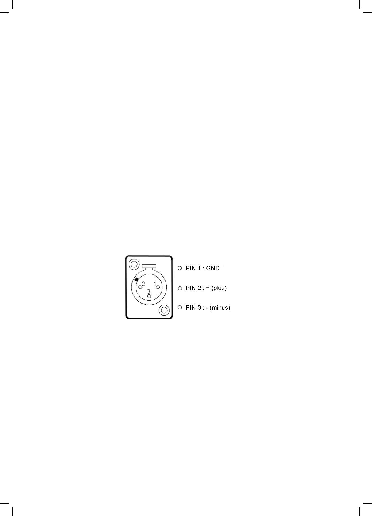
The polarity of the XLR connector output pins is shown on the diagram below:
Input connections
Before connecting any device, make sure that are all turned off.
FLS 10 balanced stereo integrated amplifier has 5 stereo inputs, high-level and variable gain:
• 3 inputs (INPUT 1, INPUT 2 and INPUT 3) are unbalanced RCA format.• 2 inputs (INPUT 4 and INPUT 5) are balanced XLR format.Highest quality cables are recommended for these connections.
The polarity of the pin XLR input is shown on the diagram below:
Moreover, it is available also a pair of RCA output labeled “REC”. It is a fixed level output, so the signal
of the selected input, can be connected to a recording device.
Do not short-circuit the REC output, as the pre outputs, balanced and unbalanced. Never connect the
left and right outputs together, it can damage the circuitry of the Class A output stage.
It is also possible to connect dynamic headphones to the connector located on the front panel. To
listen to music on the headphones only, push the “SPK” button. The close blue led, after pushing
button, will be lighter.
Do not short-circuit the output of the headphones, never connect the left and right outputs together,
it can damage the circuitry of the output stage.
Communications between Audia Flight and other brands
On the rear of FLS 10 balanced stereo integrated amplifier you find a pair (output/input) of 3.5 mm
jack plug for trigger use.
This connection allows devices from different manufacturers have adopted this mode of communica-
tion to control on/off or standby function simultaneously.
5

6
On/Off Input
select
Stand by/
On led
Set
menu
Mute Phase
Dispaly Speakers
disable
Volume/
Navigation
knob
6
RCA Inputs
1 2 3
Removable covers for
optional input cards
AC power main
and switch on
Output Right
loudspeakers
In-Out
trigger
Outputs
XLR RCA Rec
Leftchannel
Headphones
output
Rightchannel
Output Left
loudspeakers
XLR Inputs
4 5
XLR Inputs
5 4
RCA Inputs
3 2 1
Outputs
Rec RCA XLR

7
AC mains connection
Make sure that mains voltage of your unit is suit-
able to mains voltage of your home. You can
find this value on the rear of the unit. Plug the
power cord supplied on the rear socket of FLS
10 and then switch on in “I” position. The led in
center of front panel now lights in amber col-
or, indicating the standby state. The device is
ready for operating after pressing the “ON” key
(located on front panel or on remote control).
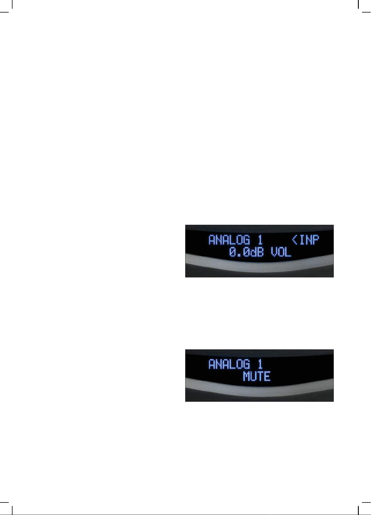
First line on display shows selected input (# 1
by default), second line shows volume level in
dB of output signal (- 90 dB, by default, the low-
est possible).
Light in center of front panel lights in blue color,
indicating operating state.
Protections
For your and amplifier safety, FLS 10 balanced stereo integrated amplifier is provided with electronic
protection systems that may be involved in following circumstances:
• excessive temperature of output stage• excessive output current (in case of short circuit or load impedance too low)• detection of a DC voltage on the output• detection of power supplies faultProtection intervention has a protective effect of stopping amplifier and its nature is indicated on dis-
play.
In any case, turn power off by rear switch, wait few minutes and switch on unit again. If problem per-
sists, contact your dealer or distributor.
For proper functioning and safety of persons and things, it is essential that your system to be
fitted with an effective earth connection, whose absence may cause malfunction.
8
Functions and controls
The display shows on the first line selected input and on the second line output level. Knob on the
front panel adjusts the volume by 0.5 dB steps for each action on a range from - 90 dB (minimum lev-
el) to + 10 dB (maximum). It is also used to navigate through menus that can be accessed by different
modes of front buttons.
• On / OffBy pressing “ON” button, FLS 10 changes sta-
tus, from ON to OFF (stand-by) or vice versa.
Led on front panel is amber when stand-by sta-
tus, blue when active status.
To turn unit off completely it is necessary to
commutate the rear switch in “O” position.
• Input selectorBy pressing “IN” button on front panel, input
selection is activated. By turning volume knob,
input changes and it is displayed.
After few seconds, state goes back to main.
Key and function are available on the remote.
• MuteBy pressing “MUTE” button, volume gradually
decreases to - 90 dB or -30 dB (please see SET > MUTE) and is shown on the display. Pressing
again the button, volume gradually returns to
previous value.
Key and function are available on the remote.

9
• PhaseBy pressing “PHASE” button, overall phase will
be changed. Selected entry is displayed. For
each input selected phase will be saved.
Function is NOT available on the remote.
• SPKBy pressing “SPK” button, output will be acti-
vated or deactivated. If output is deactivated
the blue led, close with the “SPK” button, will be
lighter.
This function is NOT available on the remote.
• Brightness of the displayBy pressing « DIM» on remote control, display
shows 1. By using « -» display shows 0 and
screen brightness is off. Any action will activate
screen for few seconds.
• Balance controlBy pressing “BAL” button on remote control,
display shows, in percentage, output level for
each channel.
By using « +», left channel level and corre-
sponding percentage decreases.
By using « -», right channel level and corre-
sponding percentage decreases.
Settings are saved.
The case of balance level is more on right chan-
nel, it is showed here.
The case of balance level is more on left chan-
nel, it is showed here.
10
• SetThis button provides access to several modes of use of amplifier. First action of this key gives access
to first mode SET GAIN INPUT, other choices are accessible by rotating the volume knob or pushing
« +» or « -» button on remote.
Here is a chart of the various modes and their meanings summary:
Keys actionsDisplay on screen Function
SET SET GAIN INPUTSetting input gain
1 x (+) SET NAME INPUTRenaming input
2 x (+) SET ACTIVE INPUTEnabling/disabling input
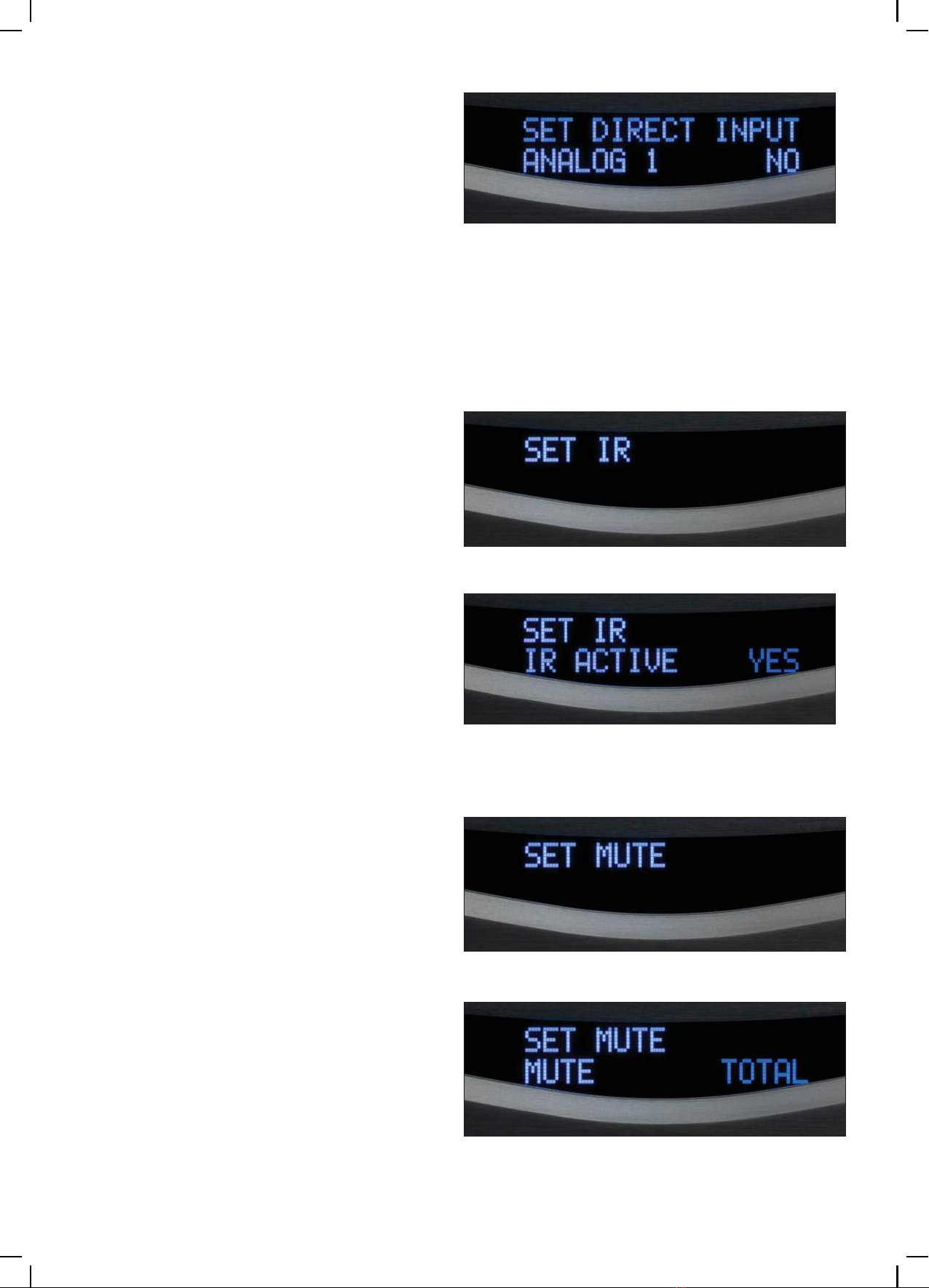
3 x (+) SET DIRECT INPUTSetting direct connection to source
4 x (+) SET IR Enabling/disabling IR receiver
5 x (+) SET MUTESetting mute level
6 x (+) SET LOAD DEFAULTResetting configuration
7 x (+) SOFTWARE RELEASE Software version management
Entry into a mode is done by pressing « SET» button, navigation button or volume keys « +» or « –»
on the remote. Confirmation of choice is made by a new action on SET.
Validation of choices is effective after few moments when display returns to first mode and then to
normal screen.
All settings are stored.
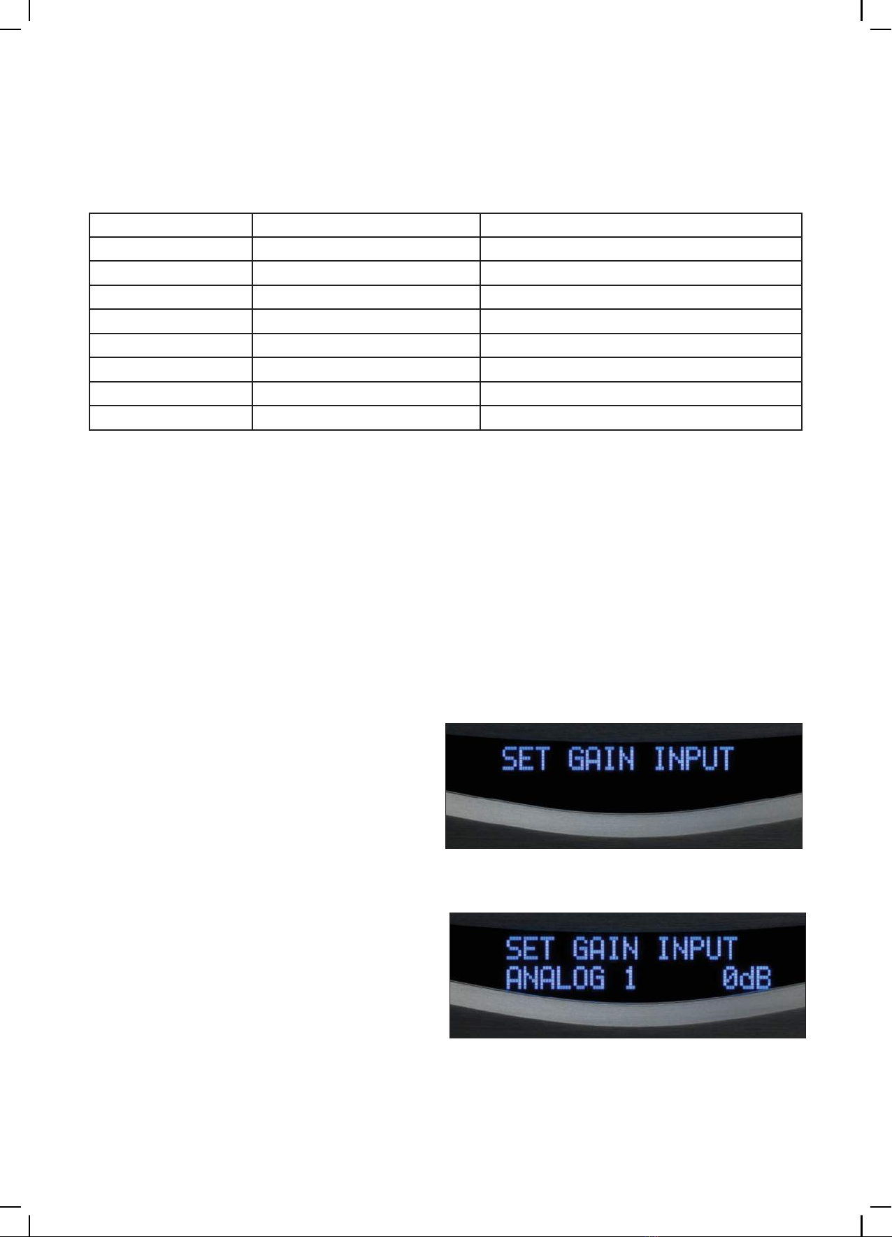
• Mode SET GAIN INPUTBy this function you can change gain of each
input between +/-6 dB.
By pressing « SET» mode, access SET GAIN INPUTis given. On second raw is shown the
selected input. By turning volume knob, input
changes and it is displayed.
Further confirming SET, gain of selected input
flashes and it can be increased or decreased,
by 1 dB steps, up to 6 dB maximum, in order to
equalize levels.
Waiting for few seconds, menu is back in previ-
ous status (input selection for gain input). Wait-
ing for more seconds, menu is back to initial
SET menu. Waiting more time, configurations
are stored and exit from SET menu.
11
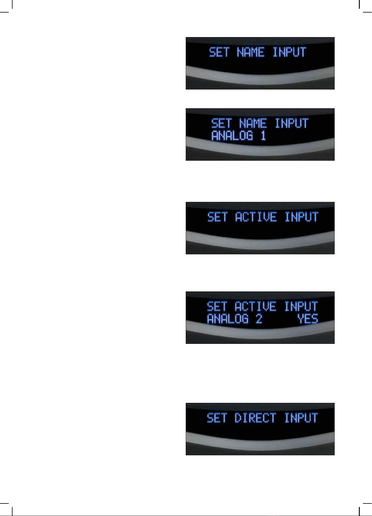
• Mode SET NAME INPUTBy this function you can rename each input us-
ing up to 8 alphanumeric characters.
By pressing « SET» mode, access SET NAME INPUTis given. On second raw is shown the
selected input. By turning volume knob, input
changes and it is displayed.
Further confirming SET, first character flashes,.
Acting on volume button « +» or « –», char-
acters scroll until the choice is validated by the
SETaction. This action makes next character
flashing. Validation of this selection is as previ-
ous one.
Once all 8 characters (or spaces) have been se-
lected and validated, display returns to choice
of entry. In absence of any instruction, configu-
ration is back to normal.
• Mode SET ACTIVE INPUTBy this function you can activate or deactivate
each input except the one selected before to
come in set menu.
By pressing « SET» mode, access SET ACTIVE INPUTis given. On second raw is shown the
selected input. By turning volume knob, input
changes and it is displayed.
Further confirming SET, YES (active status) is
shown flashing. Status can be changed as inac-
tive (NO) by rotating knob.
Waiting for few seconds, menu is back in pre-
vious status (input selection for active input).
Waiting for more seconds, menu is back to ini-
tial SET menu. Waiting more time, configura-
tions are stored and exit from SET menu.
We suggest you to deactivate all not connected
inputs.
• Mode SET DIRECT INPUTBy this function you can configure one or more
input in direct connection to power amp.
CAUTION: the signal level of this input is no
longer attenuated by the preamplifier; level
could be excessive to speakers or listener!
12
By pressing « SET» mode, access SET DIRECT INPUTis given. On second raw is shown the
selected input. By turning volume knob, input
changes and it is displayed.
Further confirming SET, NO (direct status inac-
tive) is shown flashing. Status can be changed
as active (YES) by rotating knob.
Waiting for few seconds, menu is back in pre-
vious status (input selection for direct input).
Waiting for more seconds, menu is back to ini-
tial SET menu. Waiting more time, configura-
tions are stored and exit from SET menu.
• Mode SET IRBy this function you can activate or deactivate
IR receiver.
CAUTION: if IR is deactivated, remote control will not work, you can use the front panel com-
mand only.
By pressing « SET» mode, access SET IRis giv-
en. On second raw is shown flashing the active
IR status (YES). By turning volume knob, IR sta-
tus changes and it is displayed (NO).
Waiting for few seconds, menu is back to initial
SET menu. Waiting more time, configurations
are stored and exit from SET menu.
• Mode SET MUTEBy this function you can configure if mute func-
tion decreases to a minimum of - 90 dB or re-
duces volume of 30 dB.
By pressing « SET» mode, access SET MUTE is
given. On second raw TOTAL is shown flashing
(-90 dB). By turning volume knob, MUTE status changes and it is displayed (-30 dB).
Waiting for few seconds, menu is back to initial
SET menu. Waiting more time, configurations
are stored and exit from SET menu.
13
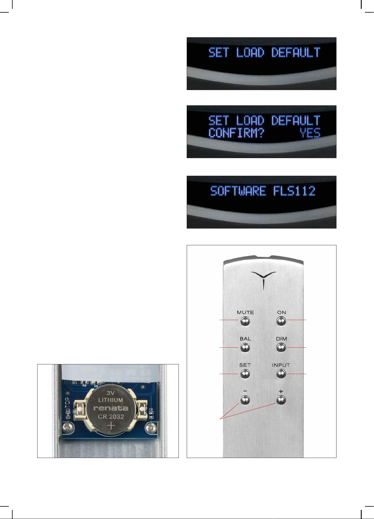
• Mode SET LOAD DEFAULTThis mode allows you to undo any configura-
tion selected by the SETmenu and so to reset
device back in its original state from factory.
By pressing « SET» mode, access SET LOAD DEFAULTis given. On second raw is shown
flashing NO. By turning volume knob, status
changes and it is displayed YES.
In this case, waiting for few seconds, COPY..., is
shown and all parameters are now in its original
state from factory.
• Mode SOFTWARE RELEASEThe last mode in SETmenu is about software
version management.
Remote controlYou will find on remote control the most import-
ant functions present on front panel of amplifier.
Menu navigation is done with « +» button, cor-
responding to rotate volume knob clockwise,
or « –» button corresponding to volume knob
counterclockwise rotation. A reduction in the
efficiency of remote is a sign of low battery. To
replace it (1 x 3V, CR2032), open remote con-
trol bottom by loosening screws, using the tool
provided. Check correct polarity for the new
battery and insert it in compartment: + pole up-
side.
Mute On/Off
Balance Dimming
Set
menu
Volume/
navigation
Input
select
14
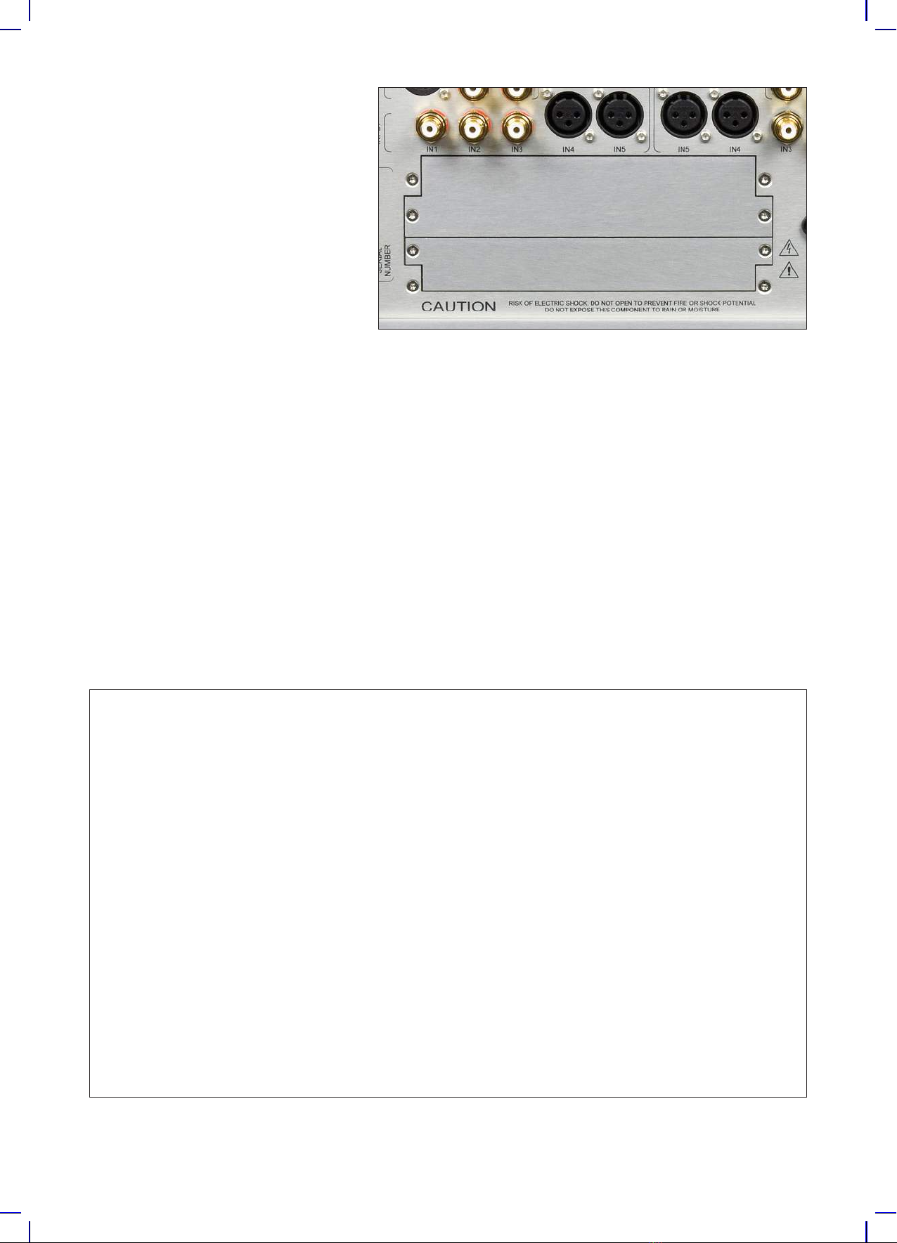
Optional boards
The FLS 10 balanced stereo amplifier
has two small removable panels on
the back where it is possible to insert
several optional boards including
phono MM/MC, DAC, analog input
and more. Please visit our website to
see latest news and optional cards
for your product.
Listening tips
Even if the device has already been run for fifty hours, during which operations and tests have been
successfully passed, we advise you to continue for two hundred hours, provided that the running
occurs in the presence of a signal.
During a long period of disuse, the complete powering off by the switch on the rear panel is recom-
mended. The FLS10 balanced stereo integrated amplifier is able to reveal nuances and extremely
subtle details present in the recordings, we recommend to combine it judiciously and in synergy with
other elements of your system, including connections.
Care and maintenance
To remove dust on the box, use a feather duster. Do not attempt to clean the surfaces brushed with
alcohol or any other similar solvent, using a simple wet microfiber cloth possibly to remove stains.
Do not install the amplifier in a place subject to direct sunlight or close to electroluminescent light
sources because they can cause troubles with the remote control working.
Technical data
Output power per channel: 200/380/700 Wrms (8/4/2 Ohm)
Inputs: 3 unbalanced RCA + 2 balanced XLR
Outputs: 1 balanced XLR + 1 unbalanced RCA
Gain range: from -90 dB to +10 dB, step 0,5 dB
Frequency response: 1 Hz ÷ 0,7 MHz (1 Wrms, –3 dB)
Slew-rate: > 100 V/us (on 8 Ohm)
THD: < 0,05 %
S/N ratio: 98 dB
Input impedance: balanced or unbalanced 47 kOhm
Damping factor: > 650 (on 8 Ohm)
Main voltage: AC 100, 110/115, 220/230, 240 V , 50/60 Hz
Stand-by power consumption: less than 1 W
Nominal power consumption (no signal): 170 W
Power consumption: 840 W (200W RMS @ 8 Ohm both channels)
Dimensions and weigth: 450 x 177 x 440 mm (W x H x D) - 36 kg
Shipping dimensions and weigth: 575 x 300 x 545 mm (W x H x D) - 44 kg


Via Alfio Flores, 7
00053 Civitavecchia
(RM) - Italy
www.audia.it
Made in Italy
UK rel. 2.0
Other Audia Flight Amplifier manuals


