Audio Control D-4.800 User manual
5
~°"'1-~Wchn.
........
+
AudioContl'OI
Makine
Good
Sound
Grcilt•
D-4.BDD
Two/Thttt/
Four
Channd
Hip
Power
Ampl
,
fler
osr
Matrix P,ocu~ns,
kul
Time
Anaty:w. Sttnat
Dtlay,
Aclt,t
S9c:aktf
lewl
lnpuu.
S11NI
Summ,ne,
lJnc
lM
Outputs.
A«ulA!S•
hu
At..sto,ation
MllC"'Soum:
Op
DttKllOl'I,
cro-S.cnal
Sa!M:
2
◄
cll
/Octr,t
l.ltlk'llflu-Mq
Ctos5CMJ'1.
lqu.Wution.
AsUCNbl<t
lwnott
Lna
Mid
c.,
Prud
Control
Oes1cned
in
th<
hof.c
Nonhwtst
USA
www
.iudiocontrol com
AudioContPOI
®
Making Good Sound
Great™
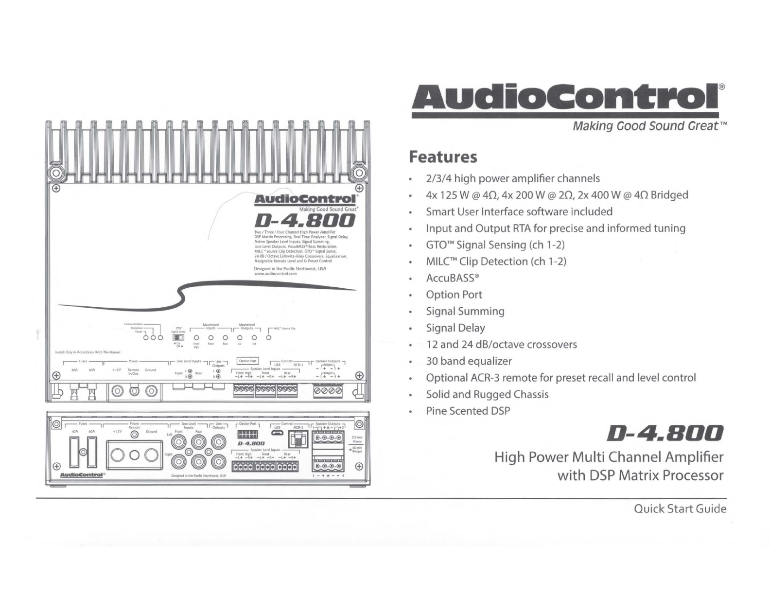
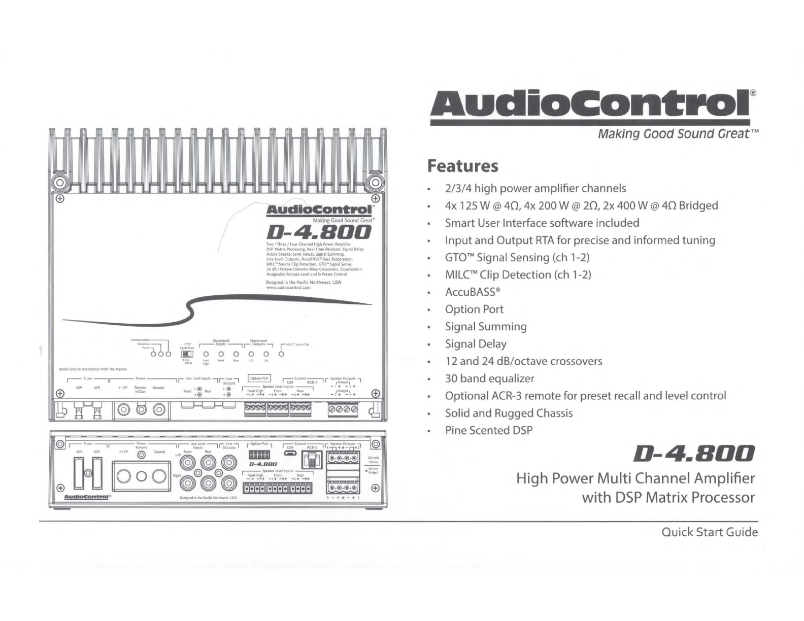
Features
•
2/3/4
high
power
amplifier
channels
•
4x
125 W @
40,
4x 200W @
20,
2x 400W @
40
Bridged
• Smart User Interface software included
Input
and
Output
RTA
for
precise and
informed
tuning
•
GTO
™Signal Sensing (ch 1-2)
MILC™Clip Detection (ch 1-
2)
• AccuBASS®
•
Option
Port
• Signal Summing
• Signal Delay
12and
24
dB/octave crossovers
• 30 band equalizer
• Optional
ACR
-3 remote
for
preset recall and level control
• Solid and Rugged Chassis
Pine Scented
DSP
D-4.BOO
High Power
Multi
Channel Amplifier
with
DSP
Matrix Processor
Quick StartGuide

Important
Safety Instructions
1.
Read
these instructions.
2.
Keep
these instructions.
3. Heed all warnings.
4. Followall instructions.
5. Do
not
use
this apparatus nearwater.
6. Clean only
with
a
dry
cloth.
7. Do
not
blockany ventilation openings.Install in accordance
with
the
manufacturer'sinstructions.
8. Do
not
install near any heat sources such
as
mufflers,silencers, exhaust
pipes,
or
other
apparatus (including amplifiers)
that
produce heat.
9. WARNING: Improperinstallation may lead
to
permanent injury
or
death.
Installation
of
the apparatus must
be
done
with
greatcare
by
qualified
personnel,
to
preventdamage
to
fuel lines, power, and otherelectrical
wiring, hydraulic brake lines, and othersystems,
that
might
compromise
vehicle safety.
10.
Provide +12V and Ground insulated wiring
of
between 8 and 3
AWG
to
ensure adequate current
to
the
amplifier.
11
.
Use
rubber grommets
to
protectwiring wheneverpassing wires
through
metal openings
or
bulkheads.
12.
Only
use
attachments/accessories specified
by
the manufacturer.
13.
Refer all servicing
to
qualified service personnel. Servicing
is
required
when the apparatus
has
been damaged in any way, such
as
the powerin-
put
terminals are damaged, liquid
has
been spilled orobjects have fallen
into
the apparatus, the apparatus
has
been exposed
to
rain
or
moisture,
does
not
operate normally,
or
has
been dropped.
2
D-4.BOO
14. This apparatus shall
not
beexposed
to
dripping
or
splashing, and no
object
filled
with
liquids, shall be placed
on
the
apparatus.
15.
Fuses
shall be replaced only
with
the
correct typeand fuse value, and
only
when
the
apparatus
is
powered off.
16. Exposure
to
high sound pressure levels may lead
to
permanent hearing
loss
.
Take
every precaution
to
protectyour hearing.
£.
The lightningflash
with
arrowhead symbol
within
an
equilateral
ill
triangle
is
intended
to
alert
the
user
to
the presence
of
uninsulated
"dangerous voltage"
within
the
product
'senclosure,
that
maybe
of
sufficient magnitude
to
constitute a risk
of
electric shock
to
persons.
The exclamation
point
within
an
equilateral triangle
is
intended
to
alertthe user
of
the
presence
of
important
operating and mainte-
nance (servicing) instructions in
the
literatureaccompanying the
appliance.
Caution:
to
reduce
the
risk
of
electric shock,
do
fr...
le
~
It\
not
disassemble
the
apparatus, otherthan
to
ill
Uli,r,;~i-
ffi
remove
the
top
panel
to
access
the
controls.
wARN1NG
:sHocKHAZARo-00NoroPEN
There are no user-serviceable parts inside. Refer
AneNr10N
:R1sauE0Ec
H
oc.NEP
AsouvR1R.
servicing
to
qualified personnel.
Recycling notice:
If
the
time
comes and this apparatus
has
fulfilled
its destiny,
do
not
throw
it
out
into
the
trash.
It
has
to
becarefully
recycled for
the
good
of
mankind,
by
afacility specially equipped
for
the
safe
recycling
of
electronic apparatii.
Please
contact your
local orstate recycling leaders forassistance in locating a suitable
nearbyrecycling facility.
Or,
contact
us
and we
might
be able
to
repair
it
foryou.
QuickStartGuide
Features
1 2
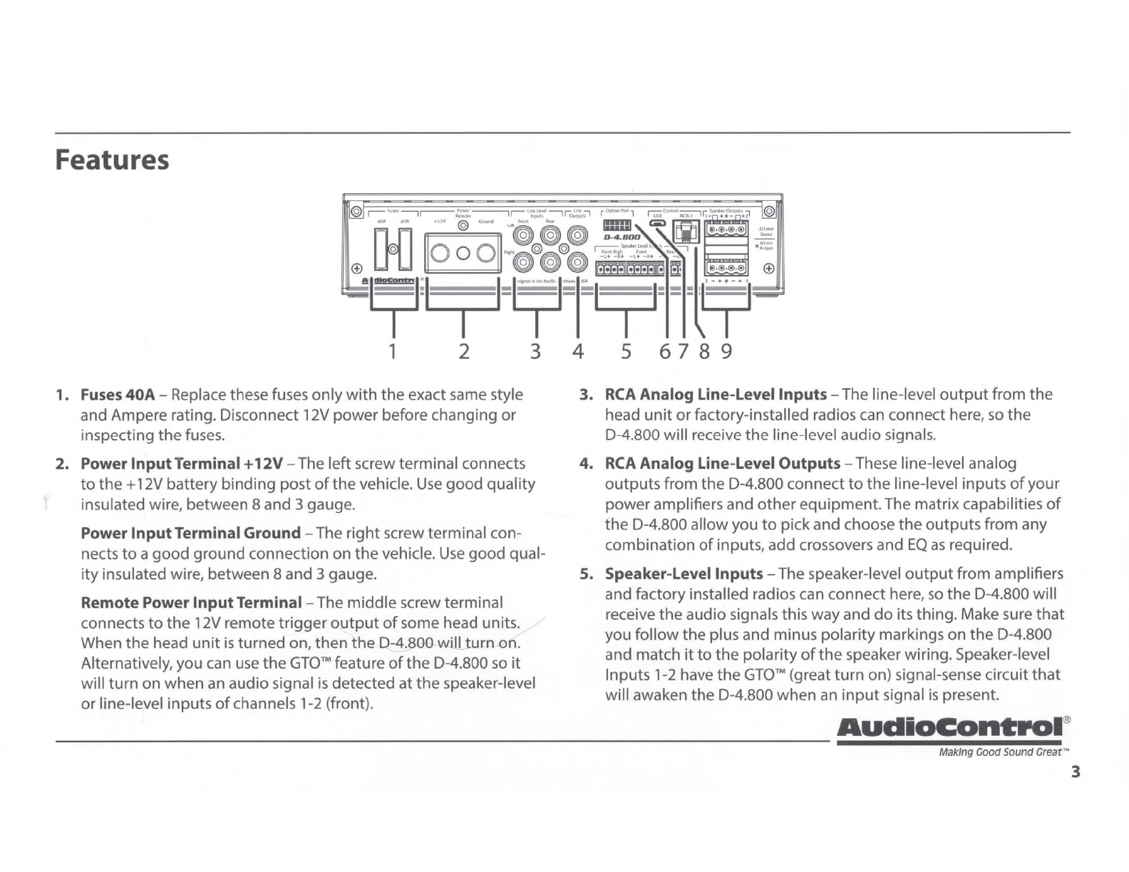
1.
Fuses
40A-
Replace these fuses
only
with
the
exact same style
and Ampere rating. Disconnect 12V
power
before changing or
inspecting
the
fuses.
3
2. Power InputTerminal+
12V
-The
left
screw terminal connects
to
the+
12V battery
binding
post
of
the vehicle.
Use
good
quality
insulated wire, between 8 and 3 gauge.
Power InputTerminal Ground -The
right
screwterminal con-
nects
to
a
good
ground connection on
the
vehicle.
Use
good
qual-
ity
insulated wire, between 8 and 3 gauge.
Remote Power InputTerminal -The
middle
screwterminal
connects
to
the 12V remote
trigger
output
of
some head units.
When
the
head
unit
is
turned on,
then
the
D-4.800
will
turn
on
.
Alternatively, you can
use
the
GTO™
feature
of
the
D-4.800 so
it
will
turn
on when
an
audio signal is detected at
the
speaker-level
or
line-level inputs
of
channels 1-2 (front).
4 5 6 7 8 9
3.
RCA
Analog Line-Level Inputs-The line-level
output
from
the
head
unit
or
factory-installed radios can connect here,
so
the
D-4.800 will receive
the
line-level audio signals.
4.
RCA
Analog Line-Level Outputs -These line-level analog
outputs
from
the
D-4.800 connect
to
the
line-level inputs
of
your
power amplifiers and
other
equipment.The matrixcapabilities
of
the
D-4.800 allow you
to
pickand choose
the
outputs
from
any
combination
of
inputs, add crossovers and
EQ
as
required.
5. Speaker-Level Inputs -The speaker-level
output
from amplifiers
and factory installed radios can connect here,
so
the D-4.800 will
receive
the
audio signals this wayand
do
its
thing
.Make sure
that
you
follow
the plus and minus polar
ity
markings
on
the
D-4.800
and match
it
to
the
polarity
of
the
speaker wiring. Speaker-level
Inputs 1-2 have
the
GTO
™(great turn on) signal-sense circuit
that
will awaken
the
D-4.800
when
an
input
signal
is
present.
AudioContPOI
®
M
ak
ing
Go
od S
ou
nd
Great ·· 3

Features continued
6. Option Port -This
port
allows you
to
connect
our
optional
Bluetooth adapter,
so
you
can
stream audio
into
channels 7 and 8
from your Bluetooth-enabled devices. Or setup and control your
D-6.1200
with
the DM Smart app. Furtherdetails will be available
when this accessory and others become available.
7.
USB
Micro
Connector-
This connects
to
your computer's
USB
A
port
to
configure the D-4.800
with
the
control software.
8. Remote Control
Connector-
This connects
to
the optional
ACR-
3 remote level control using astandard telephone cord.
9. Speaker-Level OutputTerminals -These screw terminals
connect
with
speaker wire
to
your
loudspeakers. Make sure
that
the average combined speaker impedance does
not
dip
below2
Ohms, or4 Ohms in Bridged
mode
.Outputs 1and 2 can be com-
bined in Bridge mode
to
powerasingle speaker.
Use
the 1+ and
2-terminals only. Outputs3 and 4
can
also becombined in bridge
mode,
use
the
3+ and 4-terminals only.
1
O.
Power
LED
-
If
you have connected your batterypower, vehicle
ground, and turn-on lead (or
GTO™
signal sensing) correctly, then
this
light
should be
GREEN
to
indicate
the
power
is
ON.
An inter-
nal blue
glow
will also emanatefrom
the
heatsink
area
to
indicate
that
the power
is
ON.
There are times when this blue
glow
will
flash, such
as
during power-up, and when
the
protection circuits
have detected a problem.
See
the
table below.
11.Protection
LED
-The D-6.1200 amplifier has
built
in diagnostic
codes
to
tell you exactly
what
is
going wrong should
the
amplifier
detecta problem. Below
is
a list
of
diagnosticcodes
to
help you.
4
D-4.BOO
If
the
protection
LED
should come on, read
the
red codes quickly
before turning
off
the
system and investigating. Note
that
the
blue powercodes mentioned in the table are
for
the
internal blue
glow
from behind the heatsink area, and
not
the
power
LED
which
is
green.
If
there
is
problem
with
the
unit,
the
sensing circuit will
shut
down
the
unit
to
protect itself, and this protection
LED
will
come on. For example, this
might
happen
if
the temperature
with-
in
the
unit
is
too
high. Check there
is
good ventilation around
the
unit, and
that
the
speaker wires are
not
short circuiting, and check
that
you are
not
running
too
low
of
a speaker impedance.
Power
(Blue)
Codes
(These are
the
blue
LEDs
inside
the
unit)
Power
Up
0000000000000000
Reset
Boot
0000000000000000
Protection
Activated
0000000000000000
Protection (Red)
Codes
(This
is
the
red Protection
LED
on
the
unit)
1
Short
0000000000000000
2 Repeated Short
0000000000000000
3
Under
Voltage
0000000000000000
4 OverVoltage
0000000000000000
5
DC
Offset
0000000000000000
6 Thermal Heatsink
0000000000000000
7 ThermalTransformer
0000000000000000
QuickStartGuide

Features continued
"""=:
:;=il
--000
10
11
12 13 14
12.
Communications LED -This
LED
turns on
when
there
is
USB
acti
vity
between
the
D-4.800 and your
computer
during
set
up
.
13.
GTO™Signal Sense -
In
the
ON
position,
the
D-4.800 amplifier
will
turn
on
gracefully
when
it
detects an
incoming
audio signal
on
inputs 1and
2,
and
it
will
turn
off
aftera period
of
time
when
the
audio signal fades away
to
silence. In some situations, factory
installed audio systems may
turn
on
or"wake
up
"
due
to
conve-
niencefeatures like
door
chimes, alarms, and cell
phone
signals
that
trigger
the
source
unit
in
the
vehicle
to
comeon.
To
prevent
these
from
turning
your
audio system
on
unexpectedly,you can
bypass
the
GTO
™circuit
by
moving
the
GTO
™switch
to
the
OFF
position and use a switched 12-
volt
signal connected
to
the
Re
-
mote
In
terminal instead.
14.Maximized
Input
LEDs
-These
LEDs
illuminate when amaxi-
mum
audio signal
is
present
on
any
of
the
analog audio inputs.
During
power
-
up
, these
LEDs
and
the
output
LEDs
will
turn
on
momentarily, one after
the
other.Turn
down
the
levels
if
these
LEDs
are
on
a lot.
15 16
15.
Maximized
Output
LEDs
-These
LEDs
illuminate
when
there
is
maximum
signal present
on
any
of
the
analog audio
outputs
.Turn
down
the
output
levels
if
these
LEDs
are
on
a lot.
16.
MILC-Source Clip LED -The
MILC
™(Maximum
Input
Level
Control) patent-pending level-setting circuit (on inputs 1-2
only
)
prevents clipping and damaging distortion.
It
calculates
when
the
waveform
of
an
incoming
audiosignal is clipping, and
if
it
is,
this
LED
will
fulfill its destiny and shine
forth
.
With this advanced feature, you are able
to
optimize
the
level
of
the
incoming
audio signal until
the
Source Clip
LED
is
just
about
to
come
on
.
If
the
LED
comes on
during
normal operation, you
should adjust
the
level
of
the
audio signals before
they
reach
the
D-4.800.
Afteran inter
view
with
the
lead engineer included
the
words
"differential calculus;'and some hieroglyphics
on
a chalk board,
the
technical writer's eyes glazed overand he had
to
be
brought
round
with
a nice
cup
of
tea and
two
donuts
with
sprinkles.
AudioContPO
I®
Making Good
sound
Gr
eat~ s
System Examples
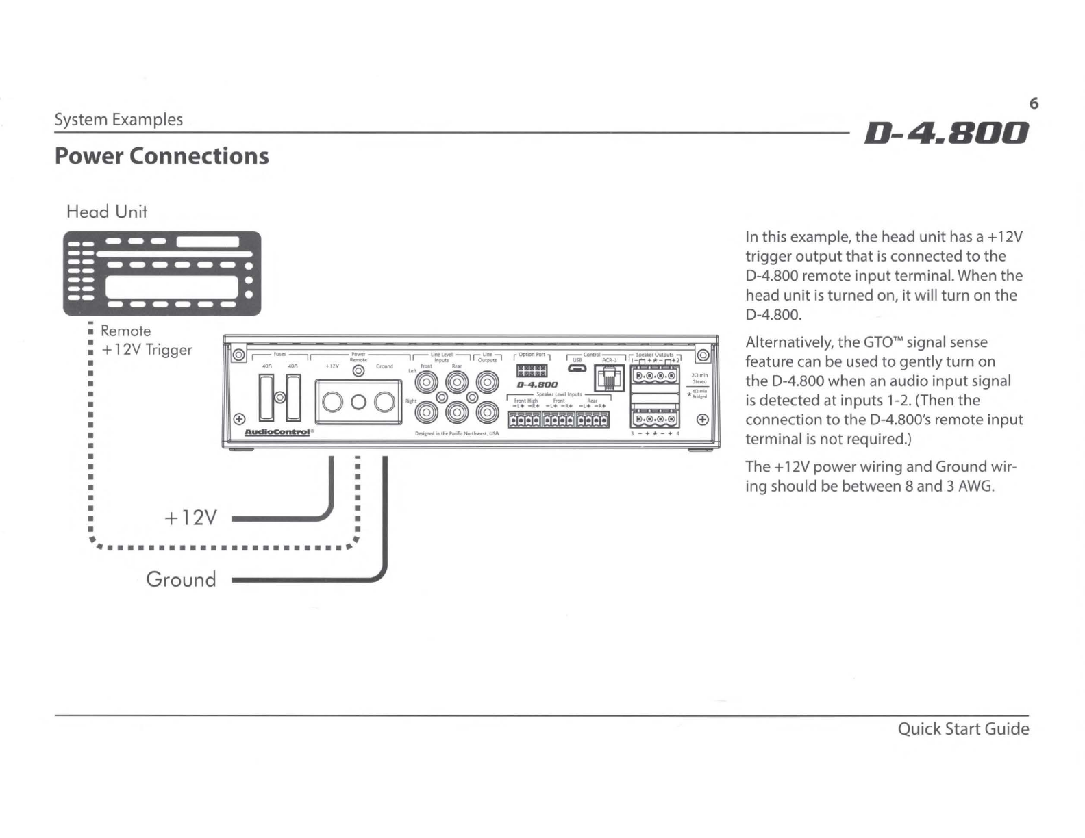
Power Connections
Head Unit
; Remote
: +12V Trigger
•
•
•
•
•
•
•
•
•
AydlOCp
•t•ul"
I
+12V
_J
I
• •
• •
•••••••••••••••••••••••••
Ground
•-n
+•-___LJ+
~-®·®·®
I
L~•®•®•®
Du.cntd1nthotflK1'c~lM
6
D-4.BDD
In this example,
the
head
unit
has
a+
12V
trigger
output
that
is
connected
to
the
D-4.800 remote
input
terminal.When
the
head
unit
is
turned on,
it
will
turn
on
the
D-4.800.
Alternatively,
the
GTO™
signal sense
feature can be used
to
gently
turn on
the D-4.800 when an audio
input
signal
is
detected
at
inputs 1-2.(Then
the
connection
to
the
D-4.800's remote
input
terminal
is
not
required.)
The+
12V powerwiring and Ground wir-
ing should be between 8 and 3
AWG.
QuickStart Guide
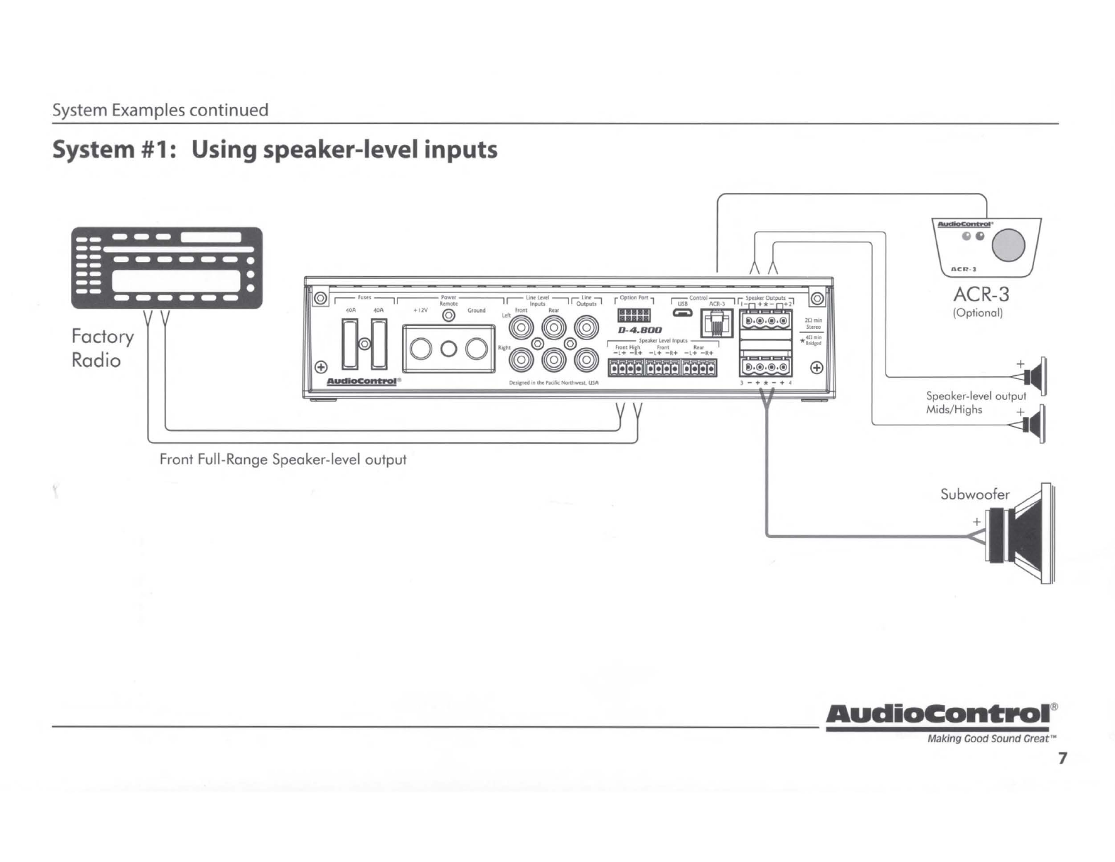
System Examples
continued
System #1: Using speaker-level inputs
Factory
Radio AUdloCpnt•OI
Front Full-Range Speaker-level
output
I
1-
n
+*-n+2
~.@,@,@
~.@,@,@
-------------------------------------
ACR-3
(Optional)
AudiOContPOI
®
Making Good Sound
Great'"
7
System Examples
continued
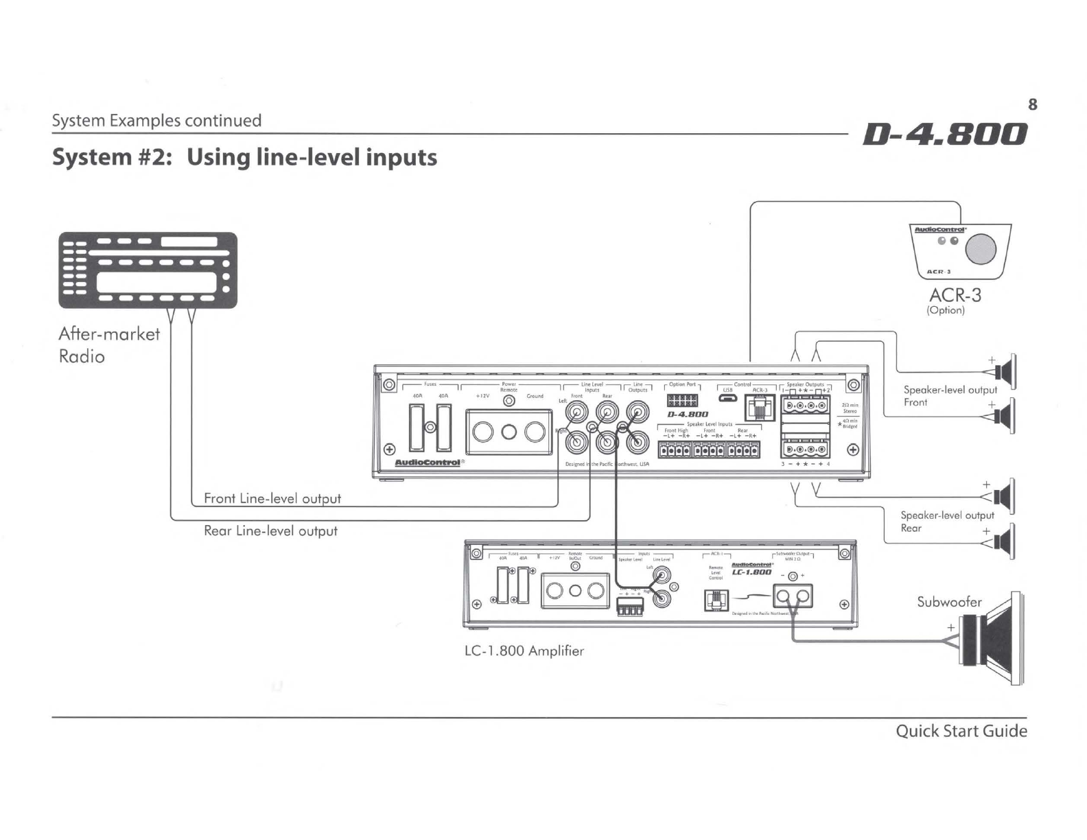
System #2: Using line-level inputs
After-market
Radio
Front Line-level
out
ut
Rear Line-level
output
Auc11oCa11tw"01
~
LC-1.
800
Amplifier
J
r AClt
'7
r~··•::a/:
''""
7
-- ·
c::'!.
LC
~
t.BDD
_ @ +
8
D-4.BOO
ACR-3
(Option)
lS
peo
k,c
le
,e
l ool
~~
Front +
~
Sp
eaker
-level
outp:
t•~
0
Rear +
I~
Quick StartGuide

System Examples continued
System #3: Using an external subwoofer amplifier
Factory
Radio
Front Speaker-level output
Rear Speaker-level output
•udlacant101
•
LC-
1.800
Amplifier
r
ACa·
11 r
~/~'
1""'1 0
--
~ ·
c!:!.
LC
- I..
B00
_ @ •
llCR
- J
ACR-3
(
Op
tion)
1
-------
-
~Jl
Speoker-level output ,
Front +
~
Audi0Cont1POI
®
------------------------------------------
Making Good
sound
Great'" 9

Installation
Installation
We
recommend
mounting
the
D-4.800 in
the
trunk/boot
or
cargo
area
of
the
vehicle.An alternative location
would
be under
the
front
seat
of
yourvehicle
if
there
is
enough room
to
install and also
to
reach
the
controls.When choosing a location, please keep these things in
mind
:
1.
Before you start, disconnect
the+
12V positive and negative
cables from
the
battery in
the
vehicle
to
preventany damage
to
the
vehicle
or
the
amplifierduring
the
installation process.
2.
Pick a
mounting
location
that
will provide
access
to
the
controls
and connections, provide adequate ventilation, and also protect
the
unit
from heat, moisture, and dirt.
3.
The D-4.800 needs
to
be securely
mounted
using
the
four
mounting
holes located in each corner.
4.
~
Before drilling any holes, take every precaution
to
prevent
• damage
to
fuel lines, powerand
other
electrical wiring,
hydraulic brake lines, and
other
systems,
that
might
compromise
vehicle safety.
5. Always
mount
the
unit
as
farfrom
the
antenna in
the
vehicle
as
possible,and awayfrom
the
radio
or
any
other
RF
sensitive
electronics in
the
vehicle.
6.
Use
between 8 and 3 gauge insulated powercable
to
connect
the+
12Vterminal
of
the
D-4.800
to
the
positiveterminal
of
the
vehicle battery.
D-4.BOO
7.
Use
between 8 and 3 gauge insulated cable
to
connect
the
ground terminal
of
the
D-4.800
to
the
negative terminal
of
the
vehicle battery.
8.
The D-4.800
has
speaker-level inputs
that
are designed
to
ac-
cept amplified, speaker-level signals from a factory source
unit
or amplifier.
You
may need
to
refer
to
afactory service manual
or
wiring
-harness schematic
to
determinewhich wires are the
speaker wires
for
yoursystem.
If
you are unsure which are
the
speaker wires, we recommend you lookat
the
color
of
the
speak-
erwires connected
to
the
speakers and
follow
them
back
to
the
source. Connect
the
speaker wires
to
the
D-4.800 speaker-level
input
plugs using
the
correct polarity.
9.
Line-level audio signals will generallycome
from
your after-
market radio,
or
if
you are really
getting
the
most
out
of
your
car audiosystem
they
may be coming from a really awesome
product
like
the
AudioControl
LC6i
(shameless plug).There are
generally
only
two
things
to
consider when using
the
line-level
RCA
inputs:
1.
Use
good
shielded
or
twisted
pair
RCA
cables.
2.
Run
your
RCA
cables
at
least 18"awayfrom powerand speaker
cables
to
avoid picking
up
radiated noise in
your
system.
Quick Start Guide
10

Installation continued
ACR-3 Dash Control
Option
The optional AudioControl
ACR-3
dash
control
is
adual-function remote for your
D-4.800.
It
may be mounted underthedash
using its
own
bracket,
or
through a custom
hole in the dash.The endless knob should
be
within
reach
of
the
driver, and in aspot
wherethe
two
LEDs
are plainlyvisible.
Disconnectthe vehicle
battery+
12V and
Ground connections before installation.
1.
When the left
(BLUE)
LED
is
on, turn the remote knob clockwise
to
turn
the
level up, and counterclockwise
to
turn
it
down.
2.
To
recall a memorypreset
with
the
ACR-3,
press
the
knob in
to
switch from blue mode (volume control)
to
RED
mode (preset
recall).
If,
within
two
seconds, you turn the knob clockwise one
click,
it
will recall one preset higherthan you are currentlyoperat-
ing.
If,
within
two
seconds, you
turn
the knobcounter-clockwise,
it
will recall one preset lowerthan you are currentlyoperating (for
example,
to
change from Memory2
to
Memory 1
).
Top Lid Removal
The
top
lid must
be
removed
to
gain
access
to
thecontrols, and then
put
back on again
to
protect
the
controlsfrom dust bunnies.
Removal Procedure
1. Locate
the
two
screws
that
hold
the
straight edge
of
the lid onto
the connector side
of
the
amplifier.
2.
Use
the supplied hex key
to
loosen
both
screws
just
enough
until this edge
of
the lid can
lift
freely
up
just
a little. (There
is
no
need
to
remove the screws all theway, in
case
you lose them.)
3.
Slide
the
lid toward the heatsinkfins
just
atad, beforefurther
lifting
the
straight edge
of
the
lid about2': then disengage the
remaining
two
points
of
contact (under thewavy edge
).
4.
Place
the lid in a
safe
and handy place, ready
for
thetime when
you have finished adjusting the controls
to
your immense satis-
faction, and
just
before Chivers brings tea and sandwiches.
AudioContPOI
®
---------------------------------------
Making
Good
Sound Great'"
11

Quick Start
QuickStart
Before you start, please take a
moment
to
visit
our
knowledge
base
:
www.audiocontrol.com/knowledge-base.
It
will helpyou with a
plethora
of
sound advice,and help set
the
mood
for
the
installation.
1. The following details give a briefoverview
of
the
steps required
to
install
the
0-4.800 in your system. The steps beloware ex-
plained in more detail
throughout
the
on-line manual.
2.
,/4\.
Undo
the+
12Vand Ground connections
to
the
car battery
~
before making any connections
to
the
0-4
.800.
3.
When making connections, designate red
RCA
plugs
as
right,
and designate white, black,
or
grey plugs
as
left.
4.
Use
qualityinterconnectcables.
We
know from experience
that
really cheap cables can cause a
multitude
of
problems.
5.
Connect
the+
12V
input
terminal
of
the
unit
to
the+
12Vtermi-
nal
of
the
vehicle battery.
6.
Connect
the
Ground terminal
of
the
unit
to
the
negative termi-
nal
of
the
vehicle battery.
7.
Connect
the
remote powerterminal
of
the
unit
to
the
remote
turn-on switch
of
yoursource unit. Alternatively, you can skip
this connection and use
the
GTO
™Signal sensing on inputs 1-2.
8. Connectyour audio inputs
to
the
unit
-eitherspeaker-level
or
line-level
RCA.
9.
Run
the
optional
ACR
-3 remote
to
the
front
of
the
vehicle
to
adjust
the
level on
the
fly.
D-4.BOO
10.
Note
that
the
following initial setting
up
is
carefully done
with
no
speakers connected,
to
help prevent tweeterdamage (for
example) during
the
0-4.800 setup.
11.
When you are satisfied
that
all
is
looking
good
and correct,
reconnect
the
vehicle battery. Make sure
that
any external am-
plifiers are
off
.
12
. Install
the
control application
onto
your computer,
but
make
sure
that
the
computer
is
not
connected
to
the
unit
during
the
installation.
13
. Connect
the
computer
to
the
unit
using
the
USB
micro connec-
tion, and run
the
application.The
unit
will be recognized and
you can enteran initial password (1234)
that
you
can
customize
later.
14.
Use
the
application
to
adjustevery aspect
of
the
0-4.800 oper-
ation until you have
the
system
just
right. Set
up
the
optional
remote control
to
adjust
the
levels you want.
15. With
the
computer removed,
the
0-4.800 will
now
operate
just
as
you have
it
set
up
.
16. Turn
off
the
power, and connect yourloudspeakers
to
the
0-4.800
or
yourexternal amplifiers.
17. Turn on
the
system and play
the
source
at
minimum
volume
to
begin with,then bring
up
the
levels slowly.
18.
Enjoy
the
drive!
QuickStart Guide
12

Software Application
The Display
The display
has
three
ma
in sections:
Input
View,
Output
View, and Dashboard View, in
addition
to
the
top
menu
bar
(File, Tools,
Help) and
the
Memory
(1
,
2,
3,
4)
section.
For more details
of
the
software application,
please take a
look
at
the
on-line
owner
's
manual.
Input
View
This displayallows you
to
set
the
input
gains, polarities and delays.The goal
of
the
Input
View display is
to
get
all
of
the
signals
arriving
to
the
D-4.800 evenly balanced in
level, and
time
-aligned so
that
they
can be
summed
as
desired later.The integrated
Real
Time Analyzer
(RTA)
is
helpful in achieving
this objective.
1.
Select an
input
pair
from
this row, then
the
parameters shown
will
be
for
this
input
pair.
I
[It
I : I
Front
RP,H
f
rant
H,
Input
View
lli1i!
Aud10Control X
File
Tool~
H~p
AudioControl
®
Making
Good
sound Great··
13
Software Application continued
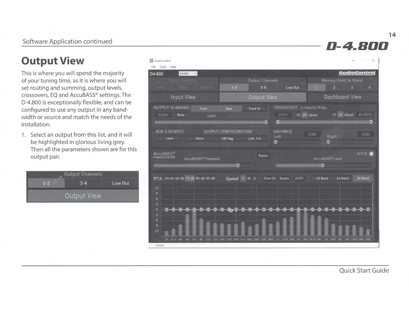
OutputView
This
is
whereyou
will
spend
the
majority
of
your
tuning
time,
as
it
is
where you will
set routing and summing,
output
levels,
crossovers,
EQ
and
AccuBASS
®settings.The
D-4.800
is
exceptionallyflexible, and can be
configured
to
use any
output
in any band-
width
or
source and match
the
needs
of
the
installation.
1.
Select an
output
from this list, and
it
will
be
highlighted
in glorious living grey.
Then all
the
parameters shown are forthis
output
pair.
14
D-4.BDD
Im
Aud10Control X
QuickStart Guide

Software Application continued
DashboardView
This displayallows you
to
conveniently
see
the
settings
of
any one
input
and anyone
output
simultaneously.All
of
the
controls
work
the same
as
the
Input
View and
Out-
put
View.
AudiOControl
®
Making Good
sound
Great··
15
+
AudiOCOntPOI
Mak.me
Good
Sound
Grut•
_______
5
D-4.BDD
1\tto
/Thr«
I
rour
Channel
Hicf,
PowaAmpl,fllf
OSP M1tnx Proctssm1.
Rt:11
Time
An1lyu,
.
S1cnal
DtlaJ'
-
AttN.
SpuUf
LM
Inputs. S1p1I
Summ,n&,
lJM
l-'
Outputs.Acal!ASSt
Sus
Restomion.
MILC'"'Sourct
O,p
Ott«tion.
CTO"'
S.,nt!Sense,
l4
di,~
llnkwiU•Rwy
CIOSSOYelJ,
lqu1huhon.
AsMpWblc
Remote
LcYd
ind
6
Pruct
Control
Dtstar,td
1n
tht
haflC
Northwtst
.
USA
www
authoconltot.
com
~::;-i I
.-":...
.-~--,r~,
r
---·-°'
000
[IJl 0 0 0 0 0 0
'"
CM
- -
...
11
1H
..
.
...
o...,-1
lfllM,_.Nort'-.
lM
Audi0Cont1POI
®
Making Good Sound Great™
Features
2/3/4
high
power
amplifier
channels
4x
125W @
40,
4x200W @
20
, 2x 400W @
40
Bridged
Smart User Interface software
included
Input
and
Output
RTA
for
precise and informed
tun
ing
GTO
™Signal Sensing (ch 1-
2)
MILC™Clip Detection (ch 1-
2)
AccuBASS*
Option
Port
Signal
Summing
Signal Delay
12and
24
dB/octave crossovers
30 band equalizer
Optional
ACR
-3 remote
for
preset recall and level control
Solid and Rugged Chassis
Pine Scented
DSP
D-4.BOO
High Power
Multi
Channel Amplifier
with
DSP
Matrix Processor
Quick StartGuide

HIGH-POWER MATRIX DSP AMPLIFIERS
HIGH-CURRENT DESIGN | 200 WATTS @ 2 OHMS | 125 WATTS @ 4 OHMS
400 WATTS @ 4 OHMS BRIDGED | SPEAKER-LEVEL INPUTS | MILCTM LEVEL MATCHING (PATENT PENDING)
MATRIX DSP PROCESSING | ACCUBASS® PROCESSING | CHANNEL SUMMING | GTOTM SIGNAL SENSE
ONE-PIECE ALUMINUM CHASSIS | OPTIONAL ASSIGNABLE REMOTE CONTROL FOR LEVEL
“MORE POWER. MORE CONTROL.
MATRIX DSP AMPLIFIERS”

AudioControl
22410 70th Ave West
Mountlake Terrace, WA 98043
www.audiocontrol.com
• Matrix DSP Processing
• Multi-channel amplifiers with AccuBASS®Processing
• 200 W @ 2 ohms, 125 W @ 4 ohms, 400 W bridged
• High Current Design
• RCA Line Inputs
• RCA Line Outputs
• Summable speaker-level inputs for OEM integration
• MILCTM Level Matching Technology (patent pending)
• GTOTM Signal Sense
• Independent 24 dB/Octave Linkwitz-Riley Crossovers
• Optional ACR-3 Assignable Dash Remote
AudioControl has paired our award winning amplifier
technology with our powerful Matrix DSP into the D-4.800
and D-6.1200 amplifies. These single unit solutions
provide unprecedented power and tuning flexibility
when you require audio perfection from your factory or
after market sound system. Using AudioControl’s DM
Smart DSP app allows complete control over all features
including 30 bands of equalization, signal time-alignment,
input delay and phase correction, AudioControl
proprietary features like AccuBASS®, GTOTM Signal
Sense, and MILCTM plus integrated input and output RTA’s
AUDIOCONTROL HIGH-POWER DSP MATRIX AMPLIFIERS
MOBILE ELECTRONICS
©2017 AudioControl, Inc. All rights reserved.
Features, appearance and specifications subject to change without notice.
MATRIX DSP
AMPLIFIERS Channels
Speaker
Level
Inputs
Continuous Power
All Channels Driven
(RMS) at 14.4V
S/N Ratio
(ref: rated
power)
THD+N
Linkwitz-Riley Crossover Bass
Processing
Pass
Thru
Dash
Remote
Mode(s) Slope(s) Freq. Range
D-6.1200 6 8
125W @ 4
Ω
200W @ 2Ω
400W Bridged (4Ω)
102 dBa <0.01%
Low Pass
Band Pass
High Pass
24 dB/oct
12 dB/oct
20 Hz -
20 kHz AccuBASS Y ACR-3
(oponal)
D-4.800 4 6
125W @ 4
Ω
200W @ 2Ω
400W Bridged (4Ω)
102 dBa <0.01%
Low Pass
Band Pass
High Pass
24 dB/oct
12 dB/oct
20 Hz -
20 kHz AccuBASS Y ACR-3
(oponal)
Other manuals for D-4.800
1
Table of contents
Other Audio Control Car Amplifier manuals


