Audio Legion AL110.4 User manual

Manual size : 150 x 210mm
Owner’s Manual
AL110.4
AL700.1D
AL1200.1D
AL1600.1D

Installation
2
If you intend to install the amplifier yourself, please read the owner’s manual carefully.
Before you start the installation, please take all the necessary precautions into consideration.
Preparation
Disconnect the negative (-) battery cable before mounting or making any connections.
Check the battery and alternator ground (-) connections. Make sure they are properly connected
and free of corrosion. Before selecting a mounting location for the amplifiers, please take cooling and
safety into consideration.
Avoid areas with excessive vibration !
For safety purposes, install the amplifier in a dry and well ventilated location and make sure no cables or
other harnesses in the car interfere with the mounting location.
+12V(B+), GND, REM CONNECTION
+12V / B+ (POWER CONNECTION)
Before mounting the amplifiers, disconnect the negative (-) wire from the battery to protect any accidental
damage to the amplifiers or the audio systems.
Connect the power cables to power terminal labeled as + 12V.
Some of the amplifiers are not equipped with fuses, so external fuses are required.
Connect one end of the fuse holder to the power cable and the other end of the fuse holder to the
positive battery terminal within 18" of the battery.
This fuse location will protect the system and the vehicle against the possibility of a short circuit
in the power cable.
Make sure that the fuses and the fuse holder are adequate for the desired application.
GND (GROUND CONNECTION)
Locate a secure grounding connection as close as possible to the amplifier.
Make sure the location is clean and provides direct electrical connection to the chassis of the vehicle.
Connect one end of an equal sized cable as the positive cable to the location of ground.
It is important that the ground cable is as short as possible, and no longer than 3 feet.
Run one end of the cable to the grounding point.
Run the other end of the cable to the mounting location.
Connect the ground cable to the terminal labeled as GND.
REM (REMOTE CONNECTION)
Run a remote turn on wire from the vehicles head unit.
Connect the remote turn on wire to the power terminal labeled as REM
Mounting
such as speaker boxes

GAIN HPF
CH4/R
CH3/L
CH2/R
CH1/L
MaxMin HPF
LPFFULL
5KHz20Hz 5KHz20Hz
GAIN
MaxMin
CHANNEL 1/2 CHANNEL 3/4
(BPF) LPF LPF HPF
5KHz50Hz 5KHz50Hz HPF
LPFFULL
(BPF)
INPUTINPUT
Panel Layout
3
(AL110.4)
1) LOW INPUT
Connect preamp signal cables from head unit to RCA input of the amplifiers.
A minimum level input of 0.2V is essential for correct operation.
2) GAIN (8V ~ 0.2V)
Matching the output voltage of the head unit’s RCA line-outs to the input section.
3) FILTER SELECTOR SWITCH
Sets the filter in either High Pass (HPF), Full Range or Low Pass (LPF) / Band Pass (BPF) operation.
4) HIGH PASS FILTER (20Hz~5KHz@12dB OCTAVE SLOPE)
Control the high pass point for the speaker outputs.
5) LOW PASS (Band Pass) FILTER (50Hz~5KHz@12dB OCTAVE SLOPE)
Control the low pass point for the speaker outputs.

GAIN LPF
REMOTE PWR
PRT
Max 30Hz 250HzMin 10Hz 40Hz
MASTER
OUTPUT
SLAVE
INPUT
SUB
SONIC
CH2/R
CH1/L
INPUT
1) INPUT
Connect preamp signal cables from head unit to RCA input of the amplifiers.
Minimum level input of 0.2V is essential for correct operation.
2) GAIN (8V ~ 0.2V)
Matches the output voltage of the head unit’s RCA line-outs to the input section.
3) SUBSONIC FILTER (10Hz ~ 30Hz)
Control the high pass point for the speaker outputs to eliminate extreme low frequencies.
4) LOW PASS FILTER (40Hz ~ 250Hz)
Controls the low pass point for speaker outputs.
5) REMOTE LEVEL CONTROL PORT
Connects to external level control.
6) REMOTE CONTROL
Turn the knob clockwise to increase level and likewise, turn the knob counter clockwise to decrease level.
7) MASTER OUTPUT / SLAVE INPUT (Only for AL1200.1D & AL1600.1D)
For linkable connection of 2 same amplifiers. Minimum impedance is 2 .
In this mode, the master amplifier will control gain settings on the subsequent slaved amplifier.
8) POWER & PROTECTION INDICATOR
Blue Power LED shows correct operation. Red LED shows general malfunction, faulty connection or
thermal protection.
Panel Layout
(AL700.1D)
GAIN LPF
REMOTE PWR
PRT
Max 30Hz 250HzMin 10Hz 40Hz
SUB
SONIC
CH2/R
CH1/L
INPUT
(AL1200.1D / AL1600.1D)
4

+12V(B+), GND, REM
(AL110.4)
(AL1200.1D/AL1600.1D)(AL700.1D)
CH2CH1
CH4CH3
PRT
PWR CH4CH3
CH2CH1
SPEAKER
OUTPUT
CH1/2 BRIDGE
CH3/4 BRIDGE
POWER INPUT
GND REM +12V FUSE
SPK BSPK A
SPEAKER OUTPUT
POWER INPUT
GND REM +12V FUSE SPK BSPK A
POWER INPUT
GND REM +12V
SPEAKER OUTPUT
GND (GROUND CONNECTION)
For connection to the chassis ground. For optimum performance 4 gauge cable is recommended.
REM (REMOTE)
Connect to switched +12V from the head unit.
+12V / B+ (POWER CONNECTION)
For connection to the positive terminal of the battery (+12).
For optimum performance 4 gauge cable is recommended.
SPEAKER OUTPUTS
Amplifier connection to loudspeakers. Minimum speaker cable is 12 gauge.
Minimum impedance is 2 . (AL110.4)
Minimum impedance is 1 . (AL700.1D / AL1200.1D / AL1600.1D)
POWER & PROTECTION INDICATOR
Blue Power LED shows correct operation. Red LED shows general malfunction, faulty connection or
thermal protection.
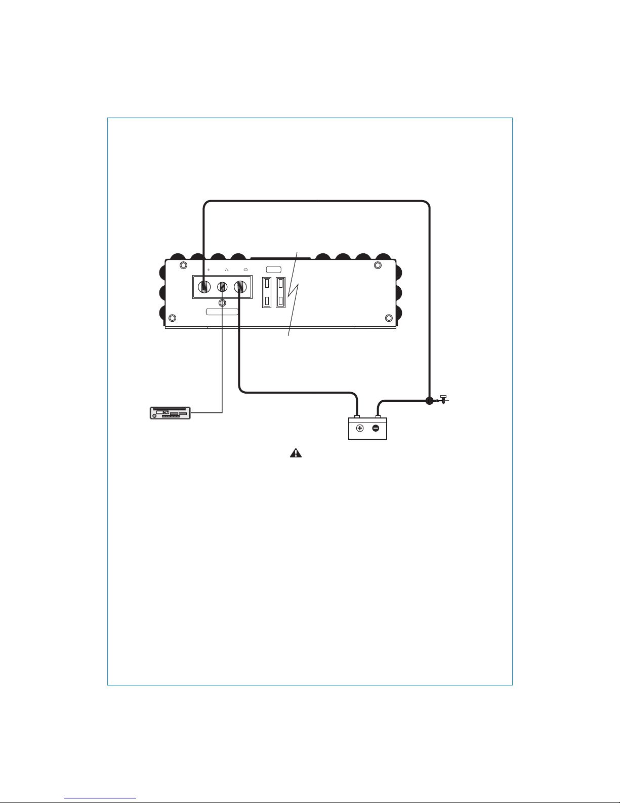
Installation of the amplifier should be done in the following steps:
1. Ensure that the ground is appropriate, then connect it to the amplifier.
2. Next step is to connect the +12V wire. Ensure all power terminals are used.
This cable has to be fused at the battery for safety precautions.
3. The final step is connecting the switched remote.
CAUTION
Before attempting to make any connections to power supply, input and output connectors,
make sure the amplifier is in OFF state. Check polarity of cables carefully as using reversed
polarity will cause damage to amplifier. And to prevent power loss and overheating of wiring,
always use the recommended wire gauges.
CAUTION
5
POWER INPUT
GND REM +12V FUSE
+12V ), GND, REM Connection(B+
6
(AL110.4 / AL700.1D)
GROUND
HEAD UNIT
12V BATTERY
Remote
turn on
Run 12 AWG speaker cables from your speakers to the amplifier’s mounting location.
Keep the speaker cables separate from the power cables and and the amplifier’s input cables.
Use grommets where the cables have to penetrate the vehicle chassis.
Connect the speaker wires according to the terminals on each speaker.
Strip 1cm, 3/8" of insulation of the end of each cable and twist the cables strands together tightly.
Make sure there are no stray strands that might touch other cables or terminals and cause short circuit.
Connect the cable ends to the amplifier as shown in the speaker wiring diagram.
We recommend using 12 AWG speaker cables to obtain intended performance.
Keep GROUND of equal length. This drawing is for illustration purposes only.
CAUTION

SPK BSPK A
POWER INPUT
GND REM +12V
SPEAKER OUTPUT
SPK BSPK A
POWER INPUT
GND REM +12V
SPEAKER OUTPUT
SPK BSPK A
POWER INPUT
GND REM +12V
SPEAKER OUTPUT
+12V ), GND, REM Connection(B+
GROUND
HEAD UNIT
12V BATTERY
SINGLE CONNECTION
DAISY CHAIN (LINKED) CONNECTION
Remote
turn on
MASTER AMPLIFIER
SLAVE AMPLIFIER
GROUND
HEAD UNIT
12V BATTERY
Remote
turn on
Recommended fuse rating
(See page 12)
Recommended fuse rating
(See page 12)
7
(AL1200.1D / AL1600.1D)
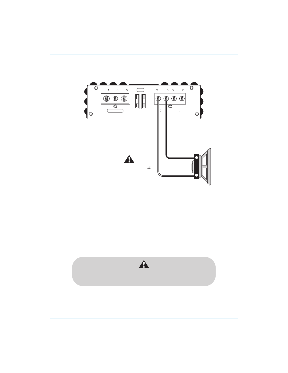
Keep GROUND of equal length. This drawing is for illustration purpose only.
CAUTION
Run 12 AWG speaker cables from your speakers to the amplifier’s mounting location
Keep the speaker cables separate from the power cables and and the amplifier’s input cables.
Use grommets where the cables have to penetrate the vehicle chassis.
Connect the speaker wires according to the terminals on each speaker.
Strip 1cm, 3/8" of insulation of the end of each cable and twist the cable strands together tightly.
Make sure there are no stray strands that might touch other cables or terminals and cause short circuit.
Connect the cable ends to the amplifier as shown in the speaker wiring diagram.
We recommend using 12 AWG speaker cables to obtain intended performance.

CH2CH1
CH4CH3
PRT
PWR CH4CH3
CH2CH1
SPEAKER
OUTPUT
CH1/2 BRIDGE
CH3/4 BRIDGE
POWER INPUT
GND REM +12V FUSE
CH2CH1
CH4CH3
PRT
PWR CH4CH3
CH2CH1
SPEAKER
OUTPUT
CH1/2 BRIDGE
CH3/4 BRIDGE
POWER INPUT
GND REM +12V FUSE
Speaker Connection
2 Channel Bridged
Speaker Impedance
4~8 ohms
CH2-MONO
SUBWOOFER
CH1-MONO
SUBWOOFER
4 Channel Stereo
+
-
+
-
CH4
CH2
Speaker Impedance
2~8 ohms
CH3
CH1
8
(AL110.4)
SPK BSPK A
SPEAKER OUTPUT
POWER INPUT
GND REM +12V FUSE
Speaker Connection
+
-
Speaker Impedance
1~8 ohms
Minimum impedance is 1 .
The amplifier is not to be Linked / Strapped.
Severe damages may occur if used in such a configuration.
Attempts to Link / Strap amplifiers will void the warranty!
(AL700.1D)
9
GAIN LPF
REMOTE PWR
PRT
Max 30Hz 250HzMin 10Hz 40Hz
MASTER
OUTPUT
SLAVE
INPUT
SUB
SONIC
CH2/R
CH1/L
INPUT
GAIN LPF
REMOTE PWR
PRT
Max 30Hz 250HzMin 10Hz 40Hz MASTER
OUTPUT
SLAVE
INPUT
SUB
SONIC
CH2/R
CH1/L
INPUT
SPK BSPK A
POWER INPUT
GND REM +12V
SPEAKER OUTPUT
SPK BSPK A
POWER INPUT
GND REM +12V
SPEAKER OUTPUT
SPK BSPK A
POWER INPUT
GND REM +12V
SPEAKER OUTPUT
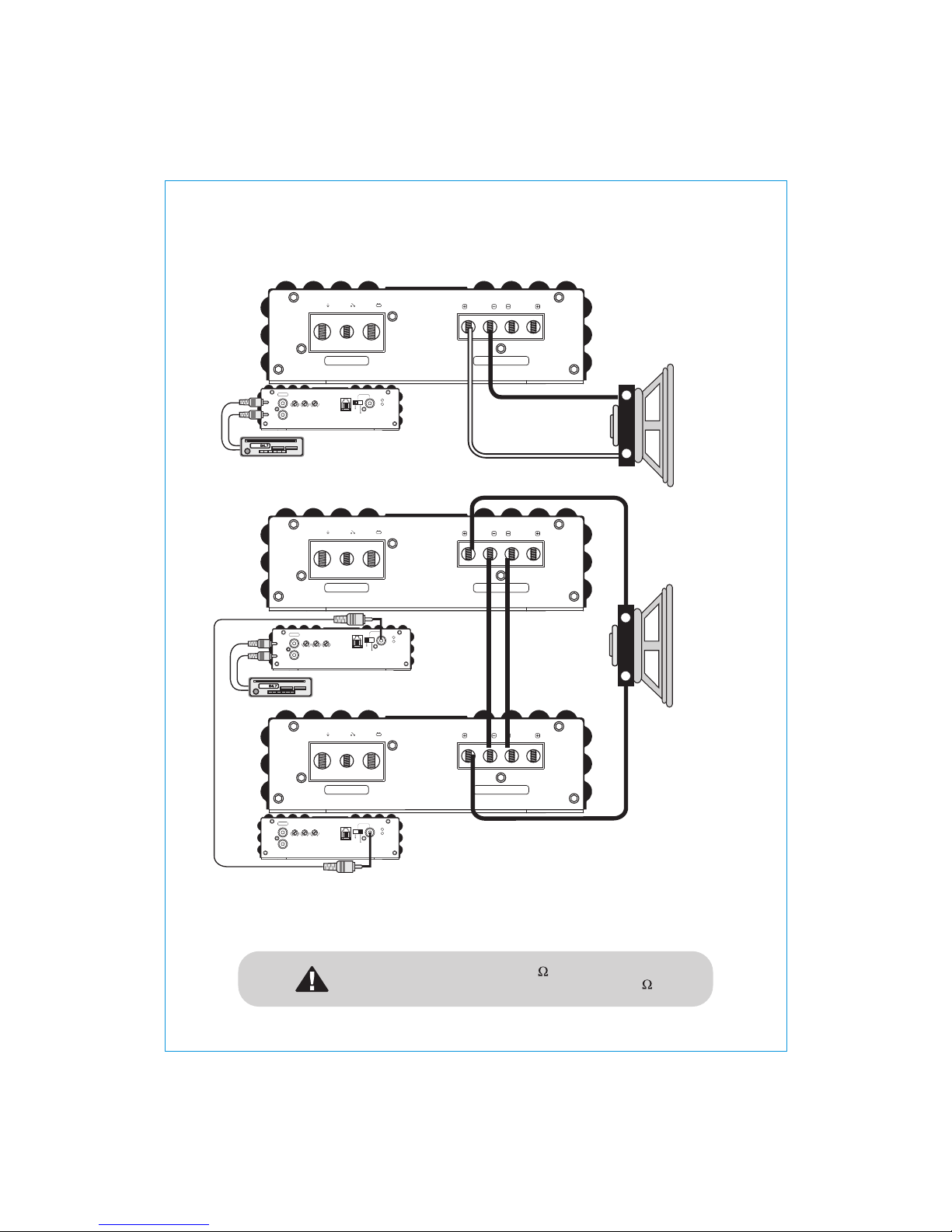
Speaker Connection
+
-
The minimum impedance as 1 unit is 1 .
In a daisy chain configuration the minimum impedance is 2 .
MASTER AMPLIFIER
SLAVE AMPLIFIER
Speaker
Impedance
2~8 ohms
SINGLE CONNECTION
DAISY CHAIN (LINKED) CONNECTION
GAIN LPF
REMOTE PWR
PRT
Max 30Hz 250HzMin 10Hz 40Hz
MASTER
OUTPUT
SLAVE
INPUT
SUB
SONIC
CH2/R
CH1/L
INPUT
HEAD UNIT
HEAD UNIT
10
(AL1200.1D / AL1600.1D)
+
-
Speaker
Impedance
1~8 ohms
Strapping connection allows linking of 2 same amplifiers to work as 1 single amplifier.
Please read the following connection diagram carefully to ensure correct connection.
Step 1. Connect the master amplifier to the head unit
Step 2. Connect the master and slave amplifier in daisy chain RCA jack as shown in the diagram.
Step 3. Connect speaker cable (+) on master amplifier to subwoofer (+)
Step 4. Connect speaker cable (+) on slave amplifier to subwoofer (-)
Step 5. Connect speaker cable (-) on master amplifier to speaker cable (-) on slave amplifier using 8 AWG wire cable.

Troubleshooting
11
Assure that the Power LED is on, if so please proceed with step # 3, if not, continue with the steps below;
1. Check the in line fuse (s) on the battery’s positive cable, replace if needed.
2. Assure that the Ground is properly attached to the vehichle’s chassis on a clean metal point, tighten or
grind the connection point once again.
3. Our amplifiers have a high voltage protection. Make sure that the operating voltage is between 8.5V~
16V and voltages above this range will cause the amplifier to go into protect.
Protect LED is on
1. The Protect LED will come on due to the possible circumstances;
a) The impedance connected is under the specified load.
b) Thermal (Overheat), allow for a more suitable mounting as recommened in the install section.
Thermal may also appear if the impedance is under the specified or the voltage is inadequate.
c) Short circuitry, voltage and DC offset.
- Short circuitry, go through all cables including speaker wires, GND, battery’s positive cable.
Voltage, please check step # 3, for DC offset, make sure that a voltage of no more than 4V is
available. Remove the RCA from the input and check whether the amplifier comes out of
protect. If so, check if the output from the Head unit has a DC of 4V, replace / repair if needed.
Audio output (no sound)
1. Assure that RCA connections from the Head unit and the amplifier is properly connected.
Check the entire cable for damages or its like. Test the RCA inputs for DC volts with the source unit on,
replace / repair if needed.
2. Check the routing of the cables, fuses and verify that all connections are connected accordingly.
3. Check whether the speakers are functional.
Turn on thump
1. Disconnect the signal input to the amplifier, then turn it on and off.
a) If the noise is cancelled, then connect a delay turn on module on the REM wire running from
the source unit to the amplifier.
b) Use another 12V source for REM lead to the amplifier. If the noise is cancelled, use a relay
to isolate the amplifier from the turn on thump.
Poor bass response
1. Check that the polarity of the speaker cables are correct. Speakers connected in anti-phase will
cancellate each other, thus the bass response will be absent.
Engine noise
1. Ensure that all signal transferring wires (RCA, speaker cables etc) are kept separately / away from
the power and the ground wires.
2. Bypass all electrical components between the Head unit and the amplifier.
Connect the Head unit directly to the amplifier’s input. If the noise is eliminated, the unit bypassed
is the one causing the noise.
3. Remove the existing ground wires for all electrical components installed. Ensure that the point of
ground is 100% metal which has been grinded free of rust, paint etc.
4. Replace the ground cable from the OEM battery / alternator and ensure it is grounded accordingly.
5. Test the battery and alternator load (can be carried out by a professional).
Ensure that the vehicle’s electrical system is in a good condition, this includes distributor,
spark plugs / wires, voltage regulators etc.

Specifications
The above specifications are subject to modifications without prior notice.
Continuous Power Output @14.4V Input
-RMS power, 4 ohms stereo
-RMS power, 2 ohms stereo
-RMS power, 4 ohms bridged
Signal To Noise Ratio
Low Pass (Band Pass) Frequency Crossover
High Pass Frequency Crossover
Frequency Response
T.H.D Continuous @ 4 ohm, 1KHz
Channel Separation
Input Sensitivity
Dimensions (mm)
Operating Voltage
Recommended Fuse Rating
: 110W x 4CH
: 185W x 4CH
: 370W x 2CH
: >90dB
: 50Hz~5KHz
: 20Hz~5KHz
: 10Hz~30KHz (+/- 1dB)
: <0.05%
: 75dB
: Variable 8V~200mV (+/- 5%)
:
: DC 8.5V~16V
: 30A x 2
175(W)x52.5(H)x240(L)
AL110.4MODEL CODE
Continuous Power Output @14.4V Input
T.H.D Continuous @ 4 ohm, 100Hz
Efficiency @ 4 ohm, 100Hz
Dimensions (mm)
-RMS power, 4 ohms mono
-RMS power, 2 ohms mono
-RMS power, 1 ohm mono
Signal To Noise Ratio
Low Pass Frequency Crossover
Subsonic Filter
Frequency Response
Input Sensitivity
Operating Voltage
Recommended Fuse Rating
MODEL CODE
: 220W x 1CH
: 420W x 1CH
: 700W x 1CH
: >90dB
: 40Hz~250Hz
: 10Hz~30Hz
: 10Hz~350Hz (+/- 1dB)
: <0.15%
: 86%
: Variable 200mV~8V (+/- 5%)
: 175(W)x52.5(H)x200(L)
: DC 8.5V~16V
: 30A x 2
AL700.1D
Continuous Power Output @14.4V Input
T.H.D Continuous @ 4 ohm, 100Hz
Efficiency @ 4 ohm, 100Hz
Dimensions (mm)
Recommended Fuse Rating
-RMS power, 4 ohms mono
-RMS power, 2 ohms mono
-RMS power, 1 ohm mono
-RMS power, 4 ohms linkable/dual mono
-RMS power, 2 ohms linkable/dual mono
Signal To Noise Ratio
Low Pass Frequency Crossover
Subsonic Filter
Frequency Response
Input Sensitivity
Operating Voltage
MODEL CODE
: 400W x 1CH
: 750W x 1CH
: 1200W x 1CH
: 1500W x 1CH
: 2400W x 1CH
: >90dB
: 40Hz~250Hz
: 10Hz~30Hz
: 10Hz~350Hz (+/- 1dB)
: <0.15%
: 86%
: Variable 200mV~8V (+/- 5%)
: 175(W)x52.5(H)x280(L)
: DC 8.5V~16V
: 100A (linked: 200A)
AL1200.1D
: 550W x 1CH
: 1000W x 1CH
: 1560W x 1CH
: 2000W x 1CH
: 3000W x 1CH
: >90dB
: 40Hz~250Hz
: 10Hz~30Hz
: 10Hz~350Hz (+/- 1dB)
: <0.15%
: 86%
: Variable 200mV~8V (+/- 5%)
: 175(W)x52.5(H)x340(L)
: DC 8.5V~16V
: 150A (linked: 250A)
AL1600.1D
This manual suits for next models
3
Table of contents
Other Audio Legion Amplifier manuals


