6
rumble like a microphone handling noise or pops.
Youhave2possiblelow-cutfrequencies–80Hzand
160Hz.Theoneyouchoosedependsonthesound,
youwanttolterout.Youcanchecktheresultwith
yourheadphonespluggedin.
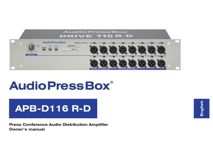
8. Compressor/Limiter operation switch
Toprovideperfectoutputsignalwithoutclippingor
distortion,youcanswitchtheCompswitchON. If
youswitchthisOFF,signalinoutputcouldcontain
signalclippingordistortion.
9. Test signal oscillator operation switch
Totestsignallevel,whichiscomingtotheoutputs,
youcanswitchthisTest1kHzsinesignaloscillator
on.Afterrecipientssetthelevelsintheirrecording
devices,youshouldswitchthisfunctionOFF.When
compressorswitchissettoON,outputsignallevel
won’texceedthismaximumoutputlevel.
10. Output level indicator bar
Youcanvisuallymonitorthelevelofoutputsignalin
7-segmentoutputindicatorbar.
11. Gain Reduction indicator bar
IfCompswitchissettoON,youcanvisuallymonitor
the level of Gain reduction on this 4-segment
indicatorbar.
12. Headphones output connector
If you want to monitor the output by your
headphones, you can plug them to this connector
(6.3TRS/Jackstereoconnector).
13. Headphones output level knob
If you have your headphones plugged in, you can
adjustthelevelofmonitoringtheoutputbyturning
thisknobtosetyourcomforthearinglevel.Pleasebe
Front panel (Input section)
1. Input XLR microphone/line connector
Inputyourmicrophoneorline-levelsourceintothis
XLRbalancedconnector.Youcanconnectanytype
ofcondensereitherdynamicmicrophonehere.
2. Phantom power switch
Ifyouareabouttousecondensermicrophone,turn
PhantompowerswitchONtofeedyourmicrophone
with 24/48V. If you are using dynamic microphone
ormicrophonewithhisownpower,youcanswitch
thisOFF.
3. Phantom power indicator
IfthePhantompowerison,thisisindicatedwithsolid
redlight.
4. Mic/Line input switch
Ifyouareusingmicrophoneasaninput,thisswitch
should be set to “Mic” position. If you are using
inputfromthemixingconsoleorCDplayer,please
setthisswitchto“Line”position.
5. Input gain level knob
After connecting your microphone, you can set
the input level to reach perfect understanding of
lectern’sspeech.
6. Input peak clip indicator
If the input level is set too high, this indicates a
possibility of distorted input signal. When this red
light continuously lights, please lower your input
level by adjusting Input gain level knob until the
indicatorstopstolight.
7. High-Pass Filter switch
This switch helps to avoid distributing low-end
carefulwhensettingthelevels,toohighmonitoring
volumescandamageyourhearingability!
14. Rechargeable battery charging status
indicator bar(*functionalwithoptionalrechargeable
batterypackBP2000installed)
If the battery pack is installed inside the Audio
PressBox®,youcanseethechargelevelsonthis
indicator. When two lights are on together, this
means, the charge level is somewhere between
thesetwovalues(when100%and50%areon,this
meansthatchargelevelissomewhereabout75%).
15. Battery operation indicator
IfAudioPressBox®runsonbatteries,thisindicator
lightsup.
16. Power ON indicator
WhenAudioPressBox®is turnedon,thisindicator
lightsup.
17. Power switch
With the power switch, you can turn your Audio
PressBox®ONorOFF.
19. Power supply connector
Plugthepowersupply to Audio PressBox®here.
If you have a model with built-in rechargeable
battery, you can recharge your Audio Press Box®
connecting the device to the mains and then you
canrunupto12hourswithoutneedofelectricity.
20. Input link
Inputlinkisaparalleloutputconnectortotheinput
connector. It can be used if you need to connect
more APBs on parallel for more outputs, but they
arefeedwiththesamesignal.Youcanlinkupto4
unitstogether.


