3
MAS-538 Quick Start Guide
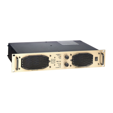
1 Secure the MAS-538 in an ASG Products mounting frame or stand-
alone on a flat surface while maintaining un-obstructed air-flow at the front
and rear of the chassis
2 Connect a dummy load or intentional radiator (antenna) to a verified
fault free, 50-ohm, BNC terminated transmission cable.
3 Connect the other end of the transmission cable to the BNC connector
labeled "OUTPUT" on the rear panel of the MAS-538
4 Apply AC power with the supplied IEC-Type AC mains power cable.
5 Energize the MAS-538 by depressing the "AC MAIN POWER" switch on
the front panel.
6 Once energized, the internal micro-controller will run a 2-second self-
test. At this time, the "TEMP" indicator will illuminate to verify the function
of the indicator. It does not indicate the condition of excess temperature
during this initial phase.
7 Once the self-test period has passed, the "CPU" LED will flash at
approximately 2-Hz rate. This is the heartbeat of the micro-controller and
should always be in this state during normal operation.
8 The MAS-538 does not energize the DC supply current to the RF
Amplifier sub-system on initial power-up. This prevents possible safety
concerns which could arise from un-planned power outages.
9 To energize the RF Amplifier sub-system, the "DC POWER" switch on
the lower, right front-panel needs to be pressed TWICE on initial power-
up. Once the switch has toggled to the ON state once, subsequent state
changes only require the button to be pressed once to re-energize.
10 Once the RF system is energized, RF energy can be applied to the
"INPUT" BNC connector on the rear panel.
