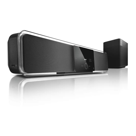
Audioaccess AVR21EN User manual

1
INSTALLATION INSTRUCTIONS

2
SAFETY INSTRUCTIONS .............................................................................................................. 7
INTRODUCTION ............................................................................................................................. 8
KEY FEATURES ............................................................................................................................. 9
Main Room ................................................................................................................................. 9
Remote Rooms .......................................................................................................................... 9
TYPOGRAPHICAL CONVENTIONS ............................................................................................ 10
IMPORTANT SAFETY INFORMATION ....................................................................................... 11
WHAT’S INCLUDED ..................................................................................................................... 13
AVR21EN Carton Contents .................................................................................................... 13
AVH21 Carton Contents ......................................................................................................... 13
WPS21 Carton Contents ......................................................................................................... 13
KP21 Carton Contents ............................................................................................................ 13
KP21R Carton Contents ......................................................................................................... 13
SYSTEM PLANNING .................................................................................................................... 14
Main Room ............................................................................................................................... 14
Remote Rooms ........................................................................................................................ 15
PRE-WIRE..................................................................................................................................... 16
Main Room ............................................................................................................................... 16
Remote Rooms ........................................................................................................................ 17
AVH21................................................................................................................................... 17
WPS21 .................................................................................................................................. 17
KP21 ..................................................................................................................................... 17
AVR21EN FRONT PANEL FEATURES ....................................................................................... 18
AVR21EN FRONT PANEL INFORMATION DISPLAY FEATURES............................................ 22
AVR21EN REAR PANEL FEATURES ......................................................................................... 24
SPF FEATURES (SOURCE POWER FLAG)............................................................................... 30
AVR21ENR1 REMOTE FEATURES............................................................................................. 33
AVR21ENR1 FUNCTION LIST ..................................................................................................... 41
MAIN ROOM INSTALLATION & SETUP ..................................................................................... 43
Installing AVR21EN and Source Components ..................................................................... 43
AVR21EN CONNECTIONS .......................................................................................................... 44
Source Connections ............................................................................................................... 44
Antennas .................................................................................................................................. 49
Monitor Outputs (Main Room Video Display)....................................................................... 50
Composite/S-Video ................................................................................................................. 50
Component Video.................................................................................................................... 50
HDMI ......................................................................................................................................... 50
Speaker Connections.............................................................................................................. 51
Subwoofer................................................................................................................................52
Pre-Out ..................................................................................................................................... 52
Control Out (Source IR) .......................................................................................................... 52
Remote ..................................................................................................................................... 52
Multiroom Link......................................................................................................................... 53
AVR21EN CONFIGURATION....................................................................................................... 53
Theater Setup .......................................................................................................................... 53
Speaker Selection and Placement......................................................................................... 53
Speaker Placement ................................................................................................................. 53
System Setup........................................................................................................................... 55
Using the On-Screen Display................................................................................................. 56
Making Configuration Adjustments ...................................................................................... 56
Setting the System Configuration Memory .......................................................................... 57
Input Setup............................................................................................................................... 58
Clock Setup.............................................................................................................................. 58
MAIN ROOM SETUP .................................................................................................................... 58
System Configuration ............................................................................................................. 58
Sources .................................................................................................................................... 59

3
Source Name ........................................................................................................................... 59
Source Audio Input ................................................................................................................. 60
Audio Mode.............................................................................................................................. 60
Dolby .................................................................................................................................... 61
DTS ....................................................................................................................................... 62
Logic 7.................................................................................................................................. 62
DSP....................................................................................................................................... 62
Stereo ................................................................................................................................... 62
Audio Upsampling................................................................................................................... 63
Source Video ........................................................................................................................... 63
Video Settings ......................................................................................................................... 64
EzSet/EQ .................................................................................................................................. 66
Output Level Adjustment ....................................................................................................... 70
SPEAKER SETUP ........................................................................................................................ 71
Speaker Configuration and Bass Management ................................................................... 72
Speaker Crossovers................................................................................................................ 75
Speaker Distances (Delay) ..................................................................................................... 76
Lip Sync ................................................................................................................................... 77
Speaker Levels ........................................................................................................................ 77
REC OUT....................................................................................................................................... 78
VIDEO MONITOR SETTINGS ...................................................................................................... 78
ADVANCED SETTINGS ............................................................................................................... 80
Front-Panel Timeout ............................................................................................................... 80
Front Panel Brightness........................................................................................................... 81
Power-On Volume ................................................................................................................... 81
On Screen Status .................................................................................................................... 82
Main Menu Time-Out ............................................................................................................... 82
REMOTE CONTROL SETUP ....................................................................................................... 82
PROGRAM CODE .................................................................................................................... 84
LEARN CODE........................................................................................................................... 86
ON-OFF COMM (On-Off Command)....................................................................................... 87
HOME THEATER MASTER CONTROL .................................................................................. 87
TV/Projector On/Off ............................................................................................................ 88
Screen Control .................................................................................................................... 91
Lighting Control .................................................................................................................. 94
Curtain Control.................................................................................................................... 97
PROGRAMMING THE AVR21ENR1 REMOTE CONTROL ...................................................... 101
TV Setup................................................................................................................................. 101
Manual Program .................................................................................................................... 101
Automatic Code Entry........................................................................................................... 103
Learning Commands............................................................................................................. 105
Learn Device...................................................................................................................... 105
Learn Button: .................................................................................................................... 106
HT Master (Home Theater Master)....................................................................................... 108
Macro Programming ............................................................................................................. 108
Resetting the Remote ........................................................................................................... 112
MAIN ROOM OPERATION......................................................................................................... 114
Basic Operation..................................................................................................................... 114
Turning the AVR21EN On or Off...................................................................................... 114
Main Room Sleep Mode.................................................................................................... 114
Source Selection............................................................................................................... 115
6-Channel/8-Channel Direct Input ................................................................................... 115
Volume and Tone Control ................................................................................................ 116
Video Processing .................................................................................................................. 117
Surround Mode Selection..................................................................................................... 117
Digital Audio Playback ......................................................................................................... 118

4
SURROUND MODE CHART .................................................................................................. 118
Dolby Digital ...................................................................................................................... 119
DTS ..................................................................................................................................... 120
Selecting a Digital Source .................................................................................................... 120
Digital Bitstream and Surround Mode Indications ............................................................ 120
PCM Playback........................................................................................................................ 122
HDCD Playback ..................................................................................................................... 122
Speaker/Channel Indicators................................................................................................. 123
Night Mode............................................................................................................................. 123
MP3 Audio Playback ............................................................................................................. 124
Important Notes On Digital Playback .................................................................................. 124
Tuner Operation .................................................................................................................... 125
Station Selection............................................................................................................... 125
Preset Tuning .................................................................................................................... 126
Recalling Preset Stations................................................................................................. 126
Recording............................................................................................................................... 126
Front-Panel Connections ..................................................................................................... 127
Output Level Trim Adjustment............................................................................................. 127
Front Panel Settings ............................................................................................................. 129
Front Panel Brightness......................................................................................................... 129
Power On Volume.................................................................................................................. 129
On Screen Status .................................................................................................................. 129
Main Menu Timeout............................................................................................................... 130
Memory Backup..................................................................................................................... 130
MAIN ROOM TROUBLESHOOTING GUIDE ............................................................................. 131
Processor Reset .................................................................................................................... 132
APPENDIX .................................................................................................................................. 133
System Defaults .................................................................................................................... 133
Personal Settings Worksheets ............................................................................................ 133
AVR21EN SPECIFICATIONS..................................................................................................... 135
MULTIROOM COMPONENTS.................................................................................................... 137
AVH21 FRONT PANEL FEATURES...................................................................................... 137
AVH21 REAR PANEL FEATURES........................................................................................ 138
AVH21 TOP FEATURES........................................................................................................ 140
AVH21 STATUS PANEL FEATURES.................................................................................... 141
WPS21 FRONT PANEL FEATURES ..................................................................................... 142
WPS21 TOP PANEL FEATURES .......................................................................................... 143
WPS21 STATUS PANEL FEATURES ................................................................................... 144
KP21 FRONT PANEL FEATURES ........................................................................................ 145
KP21 REAR PANEL FEATURES .......................................................................................... 148
KP21R REMOTE CONTROL FEATURES ............................................................................. 150
KP21R ZONE REMOTE FUNCTION LIST............................................................................. 156
MULTIROOM INSTALLATION & SETUP ................................................................................. 158
Installing W.H.E.N. System Components............................................................................ 158
Main Room. ............................................................................................................................ 158
Three Zone System. .............................................................................................................. 158
Hub System............................................................................................................................ 158
THREE ZONE SYSTEM.............................................................................................................. 160
Main Room ............................................................................................................................. 160
Remote Rooms ...................................................................................................................... 160
Keypads ............................................................................................................................. 160
Speakers ............................................................................................................................ 160
HUB SYSTEM ............................................................................................................................. 162
Main Room ............................................................................................................................. 162
Hub Installation ..................................................................................................................... 162
AVH21 Configuration ............................................................................................................ 163

5
AVH21 Hub Configuration Switch ....................................................................................... 163
HEAD END CONNECTIONS.................................................................................................. 163
AVH21 Connections.......................................................................................................... 163
Power In......................................................................................................................... 163
Uplink/Multiroom Link.................................................................................................. 165
Keypad Connections.................................................................................................... 166
Source Video In ............................................................................................................ 167
Camera Video In ........................................................................................................... 167
Zone (KP) Video Out..................................................................................................... 168
Door 1 ............................................................................................................................ 168
Door 2 ............................................................................................................................ 169
WPS21 CONNECTIONS .................................................................................................... 169
AVH21 Power Connections ......................................................................................... 169
AC Input......................................................................................................................... 169
KP21 SETUP ...................................................................................................................... 169
Keypad Address Settings ............................................................................................ 169
ZONE CONNECTIONS ............................................................................................................... 170
KP21 Connections................................................................................................................. 170
Control, Digital Audio, Data (Three Zone System) ........................................................ 170
Control, Digital Audio, Data (Hub System)..................................................................... 170
AUX In (Local Source In) .................................................................................................. 171
PREOUT (Keypad To Local High Power Amplifier or Powered Subwoofer)............... 171
Speakers ............................................................................................................................ 172
TV/Video Display............................................................................................................... 172
Connecting An External IR Sensor ................................................................................. 173
ZONE SETUP.............................................................................................................................. 174
Assign Services..................................................................................................................... 174
Assign Entertainment Services ........................................................................................... 175
Name Paging Groups............................................................................................................ 176
Name Entertainment Groups ............................................................................................... 177
Name Wake-Up Groups ........................................................................................................ 177
Name Sleep Groups .............................................................................................................. 178
Camera Setup ........................................................................................................................ 179
Name Doors ........................................................................................................................... 180
Keypad Setup By Number .................................................................................................... 181
Name .................................................................................................................................. 181
Setup Access .................................................................................................................... 182
Paging Group .................................................................................................................... 182
Entertainment Group ........................................................................................................ 182
Priority................................................................................................................................183
Permission......................................................................................................................... 183
Page Room ........................................................................................................................ 184
Monitor This Zone............................................................................................................. 185
Camera Assigned.............................................................................................................. 185
Door Answer...................................................................................................................... 186
Door Open ......................................................................................................................... 186
Wake-Up Group................................................................................................................. 187
Sleep Group....................................................................................................................... 190
Diagnostics ............................................................................................................................ 194
Settings .................................................................................................................................. 194
Run System Test ................................................................................................................... 195
Restart Network..................................................................................................................... 196
PROGRAMMING THE KP21R REMOTE CONTROL ................................................................ 197
TV Setup................................................................................................................................. 197
Manual Program .................................................................................................................... 198
Automatic Code Entry........................................................................................................... 199

6
Learning Commands............................................................................................................. 201
Learn Device...................................................................................................................... 202
Learn Button: .................................................................................................................... 202
Macro Programming ............................................................................................................. 204
Resetting the Remote ........................................................................................................... 208
MULTIROOM SYSTEM OPERATION ........................................................................................ 209
Power On................................................................................................................................210
Power Off ............................................................................................................................... 210
Volume Control...................................................................................................................... 210
Source Selection (Entertainment) ....................................................................................... 210
Source Control ...................................................................................................................... 210
Party Mode ............................................................................................................................. 214
Paging .................................................................................................................................... 214
Monitor ................................................................................................................................... 215
Wake-Up ................................................................................................................................. 215
Sleep....................................................................................................................................... 216
Door ........................................................................................................................................ 216
Setup ...................................................................................................................................... 217
On Volume ......................................................................................................................... 217
Paging Volume. ................................................................................................................. 217
Bass.................................................................................................................................... 217
Treble ................................................................................................................................. 217
Party Vol. ........................................................................................................................... 217
Speaker EQ........................................................................................................................ 218
User EQ.............................................................................................................................. 218
Preset EQ........................................................................................................................... 218
Backlight............................................................................................................................ 218
Power On Mode................................................................................................................. 218
LED Dimmer ...................................................................................................................... 219
MULTIROOM TROUBLESHOOTING GUIDE ............................................................................ 220
MULTIROOM SPECIFICATIONS ............................................................................................... 222

7
SAFETY INSTRUCTIONS
Read all of these instructions before operating and save instructions for later use.
1. Read Instructions – All the safety and operating instructions should be read before the appliance is operated.
2. Retain Instructions – The safety and operating instructions should be retained for future reference.
3. Heed Warnings – All warnings on the appliance and in the instructions should be adhered to.
4. Follow Instructions – All operating and use instructions should be followed.
5. Water and Moisture – The appliance should not be used near water – for example, near a bathtub, washbowl, kitchen sink, laundry
tub, in a wet basement or near a swimming pool.
6. Carts and Stands – The appliance should be used only with a cart or stand that is recommended by the manufacturer. An appliance
and cart combination should be moved with care. Quick stops, excessive force, and uneven surfaces may cause the appliance and
cart combination to overturn.
7. Wall or Ceiling Mounting – The appliance should be mounted to a wall or ceiling only as recommended by the manufacturer.
8. Ventilation – The appliance should be situated so that its location or position does not interfere with its proper ventilation. For
example, the appliance should not be situated on a bed, sofa, rug, or similar surface that may block the ventilation openings; or,
placed in a built-in installation, such as a bookcase or cabinet that may impede the flow of air through the ventilation openings.
9. Heat – The appliance should be situated away from heat sources such as radiators, heat registers, stoves, or other appliances
(including amplifiers) that produce heat.
10. Power Sources – The appliance should be connected to a power supply only of the type described in the operating instructions or as
marked on the appliance.
11. Grounding or Polarization – Precautions should be taken so that the grounding or polarization means of an appliance is not
defeated.
12. Power-Cord Protection – Power-supply cords should be routed so that they are not likely to be walked on or pinched by items placed
upon or against them, paying particular attention to cords at plugs, convenience receptacles, and at the point where they exit from the
appliance.
13. Cleaning – The appliance should be cleaned only as recommended by the manufacturer.
14. Power Lines – An outdoor antenna should be located away from the power lines.
15. Nonuse Periods – The power cord of the appliance should be unplugged from the outlet when left unused for a long period of time.
16. Object and Liquid Entry – Care should be taken so that objects do not fall and liquids are not spilled into the enclosure through
openings.
17. Damage Requiring Service – The appliance should be serviced by qualified service personnel when:
A. The power-supply cord or the plug has been damage; or
B. Objects have fallen, or liquid has spilled into the appliance; or
C. The appliance has been exposed to rain; or
D. The appliance does not appear to operate normally or exhibits a marked change in performance; or
E. The appliance has been dropped or the enclosure damaged.
18. Servicing – The user should not attempt to service the appliance beyond that described in the operating instructions. All other
servicing should be referred to qualified service personnel.

8
INTRODUCTION
Thank you for purchasing the Audioaccess W.H.E.N. Whole House Entertainment Network. This
system utilizes the vast technological resources of the Harman International Companies to create
a whole new approach to multi-room audio/video entertainment.
With most whole house systems, Home Theater is a secondary aspect of system design and
application. Typically, whole-house source components can be shared with the home theater, but
properly distributing A/V signals and managing source power can become burdensome in system
design and installation. W.H.E.N. resolves these issues by making the Home Theater the main
room, and component, of the system. The AVR21EN High Performance Audio/Video
Multichannel Processor/Amplifier & Multiroom System Controller is the central component for
both the Home Theater and Multiroom Systems. All Sources shared by the Home Theater and
Whole House systems connect directly to the AVR21EN. Source control and power management
are configured and managed centrally with the AVR21EN.
The AVR21EN features the latest technologies for Home Theater signal processing. All levels of
audio and video signals from line level audio, with composite or ‘S’ video to digital audio and
component video routing in addition to an HDMI output provide seamless switching from any A/V
source to numerous options of speaker configurations and video displays. Additionally, there are
endless options for audio signal processing modes including: Dolby Digital EX, Dolby Pro Logic 2,
Dolby Pro Logic IIx, Dolby Headphone, DTS, DTS Neo 6, Logic 7 and more. A Faroudja DCDi
video up-converter scales all inputs to 1080i via HDMI or component video outputs. The
AVR21EN also incorporates EzSet/EQ Home Theater calibration that automatically sets system
audio output parameters, based upon speaker configuration and room characteristics, creating
the ultimate home theater experience.
The Home Theater is controlled with the full-featured AVR21ENR1 Main Room hand-held remote
control that provides complete control of the Home Theater and provides interfacing with W.H.E.N.
Paging and Door Lock Systems.
The whole-house components include the AVH21 Audio/Video Distribution Hub, KP21 in-wall
keypad/audio amplifier and KP21R Remote Zone hand-held remote control.
The AVH21 A/V Distribution Hubs provide a scalable option for distributing whole house A/V and
control signals. Digital audio and control signals are linked to the AVH21 via an IEEE1394
network connection over CAT5e cable. Composite video signals are fed directly to the AVH21’s
via RG6 coaxial cable. Each hub can distribute the six ‘whole-house’ A/V sources from the
AVR21EN to up to seven remote rooms or ‘zones’. Additionally, up to seven video cameras can
be connected for security surveillance or incorporated with the KP21 Keypad microphones for
whole-house A/V paging and monitoring.
The KP21 Keypads provide simple, intuitive control of remote zone functions including: zone
power, source selection, source control, monitoring, paging and timers. The wall-mount keypads
fit most standard 2-gang new construction and retrofit J-boxes. The 2.5” LCD and 14 function
keys provide menu-driven control and setup functions for simple source, zone and system
operation.
The KP21’s also feature an on-board ultra-efficient 50 Watts per channel stereo digital audio
amplifier. Placing the amplifier in the local room, creates crisp, clear and powerful audio
reproduction by reducing the distance between the amplifier and the local speakers. Each keypad
has a local variable line level output allowing incorporation of local high-power amplifiers or
powered sub-woofers Line level audio from a local source can be run through the keypad
amplifier and zone speakers using the keypad’s stereo line level input. Each keypad features a
built-in microphone for whole-house paging and an IR sensor allowing control from the KP21R
hand-held zone remote control or other properly configured programmable remote. An external IR
sensor can be added to provide additional control flexibility.
The KP21R Hand-Held Zone Remote Control provides easy chair control of zone functions,
common and local source control and paging and door lock control.

9
KEY FEATURES
Main Room
•70 Watts x 7 channel surround mode
•Dual AM/FM Tuners.
•3 dedicated RS232 Sony ES DVD Changer Interface Ports.
•DCDi™ by Faroudja® video up-converter scales all inputs to 1080i via an HDMI and
component video outputs.
•Video parameters are adjustable separately for each video input.
•Surround modes include: Dolby Digital EX, Dolby Pro logic 2, Dolby Pro Logic IIx, Dolby
Headphone, DTS, DTS Neo 6, Logic 7.
•HDCD® decoding for enhanced CD playback, and MP3 decoding for use with compatible
computers.
•High-bandwidth, HDTV-compatible component video inputs for all six external common
A/V sources.
•A/V Sync delay adjustable for each input delivers perfect lip sync with digital programs or
video displays.
•Configurable HDMI Output
•Front-panel analog audio/video jacks may be used as inputs or outputs for connection to
portable products or video game consoles.
•Dedicated front-panel optical digital audio input and output.
•Switchable coaxial digital audio input/output.
•Switchable component, S, composite video and stereo line level audio input/output.
•6 12V ‘SPF’ (Source Power Flag) Inputs provide configurable source power management
to keep sources in sync with main room and whole-house functions.
•2 assignable rear panel Coaxial and Optical Digital Inputs
•1 each rear panel Coaxial and Optical Digital Outputs
•8 channel DVD audio Input
•8 channel Pre-out.
•Line-level audio, composite, S and Component video connections for each of the six
source inputs.
•2 RJ45 Multiroom link terminals for connection to W.H.E.N. Hubs and Keypads.
•1 switched and 1 unswitched AC outlet.
Remote Rooms
•Utilizes AVR21EN Processor/Controller for multiroom source control and power
management.
•Scalable design allows system configuration from 1 to 20 Zones.
•Keypad control centrally configured with easy on-screen menu setup.
•Keypad LCD and hard buttons provide menu-driven setup and control.
•KP21 keypads provide control of system, source, paging, timer and door entry functions
•KP21 keypads feature built-in 50W per channel stereo digital audio amplifiers for
maximum efficiency and performance.
•Keypad/zone local source line-level audio input for adding a zone specific component
such as a dedicated cable box, satellite receiver, DVD/CD player, video game, etc.
•Keypad/zone line level audio output for use with a dedicated zone high-power audio
amplifier or powered subwoofer.
•Whole-house paging/video monitoring.
•Configurable Page Groups.
•Remote Door entry control.
•Programmable sleep and wake-up timers for each zone, zone groups or whole-house.
•Configurable Entertainment Groups.

10
TYPOGRAPHICAL CONVENTIONS
In order to help you use this manual with the remote control, front-panel controls and rear-panel
connections, certain conventions have been used.
EXAMPLE – (bold type) indicates a specific remote control or front-panel button, or rear-panel
connection jack.
EXAMPLE – (OCR type) indicates a message that is visible in the on-screen display (OSD).
EXAMPLE
– (OCR Italic type) indicates a message that is visible on the AVR front-panel
information display.
EXAMPLE – (Eurostar type) indicates a message that is displayed on a remote control LCD
screen.
EXAMPLE – (Eurostar Italic type) indicates a message that is displayed on a keypad LCD screen.
– (number in a square) indicates an AVR21EN front-panel control or connection.
– (number in a circle) indicates an AVR21EN rear-panel connection.
– (number in an oval) indicates a button on the Main Room remote (AVR21ENR1).
– (number in a triangle) indicates a button on the Zone remote (KP21R).
– (number in a pentagon) indicates a connection or feature on the AVH21 Audio/Video Hub.
– (number in a rectangle) indicates a connection or feature on the WPS21 Power Supply Hub.
- (number in a hexagon) indicates a connection or feature on the KP21 Keypad.
- (number in a star) indicates a connection or feature on the SPF Source Power Flag Module.

11
IMPORTANT SAFETY INFORMATION
Verify Line Voltage Before Use
Your AVR21EN has been designed for use with 120-volt AC current. Connection to a line voltage
other than that for which it is intended can create a safety and fire hazard and may damage the
unit. If you have any questions about the voltage requirements for your specific model, or about
the line voltage in your area, contact your selling dealer before plugging the unit into a wall outlet.
Do Not Use Extension Cords
To avoid safety hazards, use only the power cord attached to your unit. We do not recommend
that extension cords be used with this product. As with all electrical devices, do not run power
cords under rugs or carpets or place heavy objects on them. Damaged power cords should be
replaced immediately by an authorized service center with a cord meeting factory specifications.
Handle the AC Power Cord Gently
When disconnecting the power cord from an AC outlet, always pull the plug; never pull the cord. If
you do not intend to use the unit for any considerable length of time, disconnect the plug from the
AC outlet.
Do Not Open the Cabinet
There are no user-serviceable components inside this product. Opening the cabinet may present
a shock hazard, and any modification to the product will void your warranty. If water or any metal
object such as a paper clip, wire or a staple accidentally falls inside the unit, disconnect it from
the AC power source immediately, and consult an authorized service center.
CATV or Antenna Grounding
If an outside antenna or cable system is connected to this product, be certain that it is grounded
so as to provide some protection against voltage surges and static charges. Section 810 of the
National Electrical Code, ANSI/NFPA No. 70-1984, provides information with respect to proper
grounding of the mast and supporting structure, grounding of the lead-in wire to an antenna
discharge unit, size of grounding conductors, location of antenna discharge unit, connection to
grounding electrodes and requirements of the grounding electrode.
NOTE TO CATV SYSTEM INSTALLER:
This reminder is provided to call the CATV (Cable TV) system installer’s attention to article 820-
40 of the NEC which provides guidelines for proper grounding and, in particular, specifies that the
cable ground shall be connected to the grounding system of the building, as close to the point of
cable entry as possible.
Installation Location
•To ensure proper operation and to avoid the potential for safety hazards, place the unit on a
firm and level surface. When placing the unit on a shelf, be certain that the shelf and any
mounting hardware can support the weight of the product.
•Make certain that proper space is provided both above and below the unit for ventilation. If
this product will be installed in a cabinet or other enclosed area, make certain that there is
sufficient air movement within the cabinet. Under some circumstances, a fan may be required.
•Do not place the unit directly on a carpeted surface.
•Avoid installation in extremely hot or cold locations, or in an area that is exposed to direct
sunlight or heating equipment.
•Avoid moist or humid locations.
•Do not obstruct the ventilation slots on the top of the unit, or place objects directly over them.
•There is the remote possibility that the rubber padding on the bottom of the unit’s feet may
leave marks on certain wood or veneer materials. Use caution when placing the unit on soft
woods or other materials that may be damaged by heat or heavy objects.

12
Cleaning
When the unit gets dirty, wipe it with a clean, soft, dry cloth. NEVER use benzene, aerosol
cleaners, thinner, alcohol or any other volatile cleaning agent. Do not use abrasive cleaners, as
they may damage the finish of metal parts. Avoid spraying insecticide near the unit.
Moving the Unit
Before moving the unit, be certain to disconnect any interconnection cords with other components,
and make certain that you disconnect the unit from the AC outlet.
Important Information for the User
This equipment has been tested and found to comply with the limits for a Class-B digital device,
pursuant to Part 15 of the FCC Rules. The limits are designed to provide reasonable protection
against harmful interference in a residential installation. This equipment generates, uses and can
radiate radio-frequency energy and, if not installed and used in accordance with the instructions,
may cause harmful interference to radio communication. However, there is no guarantee that
harmful interference will not occur in a particular installation. If this equipment does cause harmful
interference to radio or television reception, which can be determined by turning the equipment
off and on, the user is encouraged to try to correct the interference by one or more of the
following measures:
•Reorient or relocate the receiving antenna.
•Increase the separation between the equipment and receiver.
•Connect the equipment into an outlet on a circuit different from that to which the receiver is
connected.
•Consult the dealer or an experienced radio/TV technician for help.
This device complies with Part 15 of the FCC Rules. Operation is subject to the following two
conditions: (1) this device may not cause harmful interference, and (2) this device must accept
interference received, including interference that may cause undesired operation.
NOTE: Changes or modifications may cause this unit to fail to comply with Part 15 of the FCC
Rules and may void the user’s authority to operate the equipment.
Unpacking
The carton and shipping materials used to protect your new receiver during shipment were
specially designed to cushion it from shock and vibration. We suggest that you save the carton
and packing materials for use in shipping if you move, or should the unit ever need repair.
To minimize the size of the carton in storage, you may wish to flatten it. This is done by carefully
slitting the tape seams on the bottom and collapsing the carton. Other cardboard inserts may be
stored in the same manner. Packing materials that cannot be collapsed should be saved along
with the carton in a plastic bag.
If you do not wish to save the packaging materials, please note that the carton and other sections
of the shipping protection are recyclable. Please respect the environment and discard those
materials at a local recycling center.
At this time you should remove the protective plastic film from the front-panel lens. Leaving the
film in place will affect the performance of your remote control.

13
WHAT’S INCLUDED
AVR21EN Carton Contents:
1 - AVR21EN Processor/Controller
1 - AVR21ENR1 Remote Control
1 - Calibration Microphone
4 - AAA Batteries
2 - AM Loop Antennas
2 - FM Antennas
1 - IEC Standard two prong power cord
1 - W.H.E.N. Installation Instructions
1 - Warranty Card
AVH21 Carton Contents:
1 - AVH21 W.H.E.N. Audio/Video Distribution Hub
3 - AVH21 Hub Status Panel Labels
1 - 4 pin plug-in connector
4 - 2 pin plug-in connectors
8 - Locking pins for installation in Channel Vision C-0128E and Leviton 47605-28W structured
wiring cabinets
1 - Warranty Card
WPS21 Carton Contents:
1 - WPS21 W.H.E.N. Power Hub
1 - IEC Standard two-prong power cord
3 - WPS Hub Status Panel Labels
8 - Locking pins for installation in Channel Vision C-0128E and Leviton 47605-28W structured
wiring cabinets
8 - 4-pin plug-in connectors
1 - Warranty Card
KP21 Carton Contents:
1 - KP21 W.H.E.N. Keypad
1 - KP21 White Keypad Bezel
1 - KP21/IR Pigtail Connector
4 - Keypad to Backbox Screws
4 - Washers
1 - Backbox Compatibility Card
1 - KP21 User Reference Card
1 - Warranty Card
KP21R Carton Contents:
1 - KP21R Zone Remote
4 - AAA Batteries
1 - KP21R Owners Manual

14
SYSTEM PLANNING
The Audioaccess W.H.E.N. System is made up of three main system components, (AVR21EN
Processor/Controller, AVH21 A/V Hub, WPS21 Power Hub) and three user interfaces
(AVR21ENR1 Main Room Remote, KP21 Keypad, KP21R Remote Room Remote). When
designing a whole house system, careful planning must be made to be sure the system has been
designed properly, gets installed and configured properly and most important, works the way the
homeowner wants the system to work.
There are two main sections to be considered when designing and installing a W.H.E.N. System:
the Home Theater, or ‘Main Room’ and the Remote Rooms that will be referred to here as ‘Zones’.
Main Room
The Main Room component in a W.H.E.N. System is the AVR21EN Processor/Controller. At its
core, it is a highly evolved Audio/Video Surround Receiver. All source components that will be
played in the Main and Remote Rooms will be located near and connected to the AVR21EN. The
Home Theater speakers also connect directly to the AVR21EN.
Typically, the AVR21EN and source components would be installed in the Main Room in a wall
unit, an equipment rack or possibly in an equipment closet. Where ever they get installed, always
leave adequate space between components for free airflow to keep components from
overheating. Use cooling fans when necessary if the components are confined to a tight enclosed
area. Always leave extra space for wiring and whenever possible, when working with a
homeowner on new construction, work with the architect to provide space for the W.H.E.N.
system components that has rear access to system connections for installation and service when
necessary. If a rear access is not possible, a pullout equipment rack is recommended to provide
easy access to system connections. (If rack mounting, an optional rack-shelf is available from
Middle Atlantic Products for the AVR21EN.)
Always position components like DVD/CD players, VCRs, iPod interfaces, etc., to provide access
to the user for loading discs, tapes or connecting an iPod or other portable media player.
In some cases the Home Theater components will be at the front of the room near the screen or
video display. In designing the room layout, leave enough space between the system
components and the screen so the components do not distract the eye while theater system is in
play. (The AVR21EN has Front Panel Timeout and Brightness options that allow dimming or
turning off the front panel display.)
Key to designing the Home Theater is knowing how it will be used. What are the homeowners
habits? Are they critical movie buffs that want the full big theater effect or are they just casual
viewers that want something better than just watching TV? Will they be playing CDs or music
from a server frequently in the main room? Knowing this, along with considerations for room
dimensions and layout, will help determine the configuration and placement of the theater
speaker system. The AVR21EN is fully capable of supporting any audio mode from mono to 7.1
Surround. When planning the speaker section of the main room, pull sufficient wire from the
AVR21EN to all appropriate locations for accommodating 5.1 and 7.1 speaker systems, so that
once the walls are sealed, the necessary wires will be in place for upgrading or changing the
speaker configuration at a future date should the homeowner decide to upgrade.
The same considerations should be given to the video section of the Home Theater. The
homeowner may start out with an OK 32” TV, but at some point may want to upgrade to a wall-
mount LCD or plasma display. They may also consider hanging a projector and drop screen once
they get more familiar with the true Home Theater experience. Plan ahead. Have the homeowner
consider these possibilities and suggest they incorporate the additional wiring during construction,
so future upgrades can be accommodated without ripping the room apart.

15
SYSTEM PLANNING
Remote Rooms
The AVR21EN has a special Multiroom Link that provides a network connection to the AVH21
Audio/Video Hubs via CAT5e cable. The Multiroom Link feeds digital audio to the AVH21s for
distribution to the KP21 Keypads and receives control signals from the remote rooms for zone,
source and system control. Each AVH21 requires a WPS21 Power Hub. The WPS21 provides
individual power terminals to provide power to the AVH21 A/V Hub and each of the keypads
connected to that AVH21. Up to three AVH21/WPS21 sets can be used in a system for a
maximum of 20 Remote Zones.
The AVR21EN also provides a dedicated composite video output for each source that gets
connected to the AVH21s via RG6 coaxial cable terminated with F connectors.
When using multiple Hubs, the Multiroom Link and video connections are ‘daisy-chained’ from
one Hub to the next. The AVR21EN is connected to Hub 1 for zones 1-7. Hub 1 is daisy-chained
to Hub 2 for zones 8-14, and Hub 2 is daisy-chained to Hub 3 for zones 15-20.
One of the great features of the W.H.E.N. architecture is that the Hubs can be installed just about
anywhere. They can be installed in a utility area with structured wiring panels where the
Cable/Sat TV enters the home-up to 300 feet away from the AVR21EN. In other installations it
may be more convenient to mount the Hubs in the same location as the AVR21EN and source
components, when installed in an equipment rack or closet.
The AVH21’s and WPS21’s can be wall mounted or installed in Channel Vision C-0128E or
Leviton 47605-28W structured wiring boxes. Leave at least 3” between Hubs for airflow and
space for making connections. Though the hubs typically run cool, do not block any of the vent
holes as this can cause damage from overheating.
The KP21 Keypads get mounted in standard 2-gang electrical or low-voltage J-boxes in the
Remote Rooms. The recommended boxes are: Carlon BH235A (new work, closed box), BH234R
(retrofit, closed box), SC200A (new work, open frame), and SCS200RR (retrofit, open frame).
Keypads are typically mounted at the entrance to a room near the light switch and other room
controls. NEVER MOUNT A KEYPAD IN THE SAME J-BOX WITH A LIGHT SWITCH OR
OTHER HIGH VOLTAGE DEVICE.
The KP21 Keypads have both line level audio in and out connections. With input from the client,
additional wiring may be required to connect a local audio source such as a DVD/CD player,
video game or Cable/Satellite receiver. The variable line level out may be used to incorporate a
local high power amplifier or powered subwoofer. Permanent connection from the keypads to wall
plates may also be a consideration, making these in/outs available for use at a future time.
Given the layout of some rooms, the keypad location may be behind the user when sitting on a
couch or chair. In these situations, an external IR Receiver can be connected to the KP21
Keypad. By mounting the IR receiver at the ‘focal point’ of the room, i.e. the wall where the video
display and speakers are located, the user can control the system with a KP21R remote without
having to point back over their shoulder to use the eye on the keypad.
When designing the system, work closely with the homeowner to determine room layout so
speaker and video display placement can be set, and with that, keypad, IR receiver, speaker and
video wiring can be properly planned and installed.

16
PRE-WIRE
As part of System Planning, full consideration should be given to the wiring infrastructure that will
be required to utilize the maximum capabilities of the Audioaccess W.H.E.N.
Main Room
This section is an overview of the pre-wiring that that should be done during construction and
prior to installation for the Main Room section of the system.
Speakers (Front, Side, Rear)
Pull quality, 16AWG, 2-conductor stranded speaker wire from each speaker location to the
AVR21EN. Each paired run, (Front right/left; Side right/left; Rear right/left) should be equal
lengths to help assure proper audio reproduction. Example: if the system components are
installed on one side of the room and the Front right speaker requires a 10 foot run but the Front
left speaker requires a 20 foot run, both front speakers should have runs of 20 feet.
Video Monitor (Monitor Out, C-Video, S-Video, Monitor, Y, Pb, Pr)
If the video display is going to be mounted somewhere other than in the same wall unit as the
AVR21EN, pull the recommended video cables and terminate with an appropriate wall plate. The
AVR21EN will up-convert all video sources to Component Video or HDMI so Composite Video
and S-Video cables typically will not be required. Pull 4 RG6 coaxial cables for Component Video
and a spare, as well as an HDMI cable to where the Main Room Video Display will be mounted or
to where a projector will be installed. Terminate with a multi-terminal wall-plate.
Door A/V
Audio – Pull shielded audio cable from the door monitoring device to the AVR21EN.
Video – Pull RG6 coaxial cable from the door monitoring device to the AVR21EN.
Trigger Out
Pull 24-18AWG two-conductor stranded wire from the AVR21EN to a device such as a screen, lift,
drapes etc., to be triggered with 12V.
Remote (External IR Receiver)
Pull 24-18AWG three-conductor, stranded non-shielded wire from where the IR receiver will be
mounted to the AVR21EN.
Multiroom Link (Multiroom Application With up to Two Remote Audio Only Zones)
Pull one, CAT5e cable from each Multiroom Link terminal on the AVR21EN rear panel to each of
up to two KP21 Keypads to provide control and digital audio signals up to two Remote Rooms. It
is highly recommended that these CAT5e cables be run through the location that would be used
for installing AVH21Hubs, should the system be expanded for additional zones at a later date.
Multiroom Link (AVH21Hub Multiroom Application up to 20 Zones)
Pull one CAT5e cable from the AVR21EN to where the AVH21 A/V Hubs will be installed.
Video Source Out (Multiroom Application Only)
Pull One RG6 coaxial cable for each source to be distributed to Remote Rooms from the
AVR21EN to the AVH21(s) to provide composite video to the Remote Rooms. Pulling coax for all
six common sources is recommended even if there will not initially be six A/V components.
NOTE: All other connections will be done after construction and installation are finished. See
also: AVR21EN Connections for additional information.

17
PRE-WIRE
Remote Rooms
This section is an overview of the pre-wiring that that should be done during construction and
prior to installation for the Remote Room sections of the system.
NOTE: This section assumes that the AVR21EN, AVH21(s) and WPS21(s) are all in the same
location.
AVH21
KP 1-20 (KP21 Keypads) – Pull a home run of CAT5e cable from each KP21 keypad location to
the appropriate AHV21 for zone control and digital audio distribution to the Remote Rooms
Video Output – Pull a home run of RG6 coaxial cable from the video display location in each
Remote Room to the appropriate AVH21.
Video Input (Cam 1-7) – Pull a home run of RG6 coaxial cable from each video camera location
to the AVH21 #1.
Door 1 – Pull two-conductor 24-18AWG stranded wire from the door entry device to be controlled
by ‘Door 1’ to the appropriate AVH21.
Door 2 – Pull two-conductor 24-18AWG stranded wire from the door entry device to be controlled
by ‘Door 2’ to the appropriate AVH21.
NOTE: If using two AVH21 A/V Hubs up to four door entry devices can be controlled. If using
three AVH21 A/V Hubs up to six door entry devices can be controlled. Pull two-conductor 24-
18AWG stranded wire from the additional door entry devices to the AVH21 Hubs as required.
WPS21
KP 1-20 – Pull four-conductor, 14-AWG (recommended for use at wire length distances up to 300
feet between WPS21 and KP21) or 16AWG (up to 150 feet) stranded wire from each KP21
keypad location to the appropriate WPS21(s) to provide power to the keypad.
KP21
AUX-IN – Pull shielded stereo audio cable from the keypad location in a zone to where a local
device (DVD/CD player, video game, local Cable/Satellite receiver) or wall plate will be installed
in that zone.
PRE-OUT - Pull shielded stereo audio cable from the keypad location in a zone to where a local
device (high power amplifier or powered subwoofer) or wall plate will be installed in that zone.
NOTE: All other connections will be done after construction and installation are finished. See
also: AVH21 Connections, WPS21 Connections and KP21 Connections for additional information.

18
AVR21EN FRONT PANEL FEATURES
Figure 1 AVR21EN Front Panel
1. Main Power Switch
2. Standby/On Button
3 Headphone Jack
4 Surround Mode Group Selector
5 Surround Mode Selector
6 Tuning Selector
7 Mode Adjust Down
8 Mode Set
9 Mode Adjust Up
10 Tuner Band Selector
11 Preset Station Selector
12 Optimizer Mic Input
13 Digital Input 3 Optical Input
14 Digital Input 3 Optical Output
15 Input Source Selector
16 Digital Input 3 Coaxial Input
17. Digital Input 3 Coaxial Input/Output Status Indicator
18 Tuner Mode Selector
19 Game/Cam Component Video Input
20 Game/Cam S-Video Input
21 Game/Cam Input/Output Status Indicator
22 Game/Cam Composite Video Input
23 Game/Cam Line level Audio Input
24 Main Room Volume Control
25 Information Display
26 Delay Adjust Selector
27 Digital Input Selector
28 Channel Adjust Selector
29 Speaker Selector
30 Tone Mode Selector
31 IR Remote Sensor Window

19
AVR21EN FRONT PANEL FEATURE DESCRIPTIONS
1. Main Power Switch: Press this switch to apply power to the AVR21EN. When the switch is
pressed in, the unit is placed in a Standby mode, as indicated by the light in the Standby/On
Button [square 2] turning red. The switch MUST be pressed in to operate the unit. To turn
the unit off and prevent the use of the remote control, this switch should be pressed until it
pops out from the front panel. NOTE: This switch is normally left in the “ON” position.
2. Standby/On Button: When the Main Power Switch is pressed in so that it is in the “ON”
position, press this button to turn the AVR21EN on. When the unit is in the Standby mode,
the light in the middle of the Button is red. When the unit is on, the light in the button is green.
3. Headphone Jack: This jack may be used to listen to the AVR21EN’s output through a pair of
headphones. Be certain that the headphones have a standard 1/4" stereo phone plug, or that
you use an adapter, as needed, to convert the plug on your headphones to the 1/4" jack used
on the AVR. When the headphone jack is in use, the main room speakers will automatically
be turned off and the unit will output a standard stereo signal. You may also use one of the
Dolby Headphone modes for an enhanced listening experience. For more information on
headphone listening, see section: Main Room Operation/Volume and Tone Control.
4. Surround Mode Group Selector: Press this button to select the top-level group of surround
modes. Each press of the button will select one of the surround mode categories. Once the
button is pressed so that the name of the desired surround mode category appears in the on-
screen display and in the Lower Display Line [square 34], press the Surround Mode
Selector [square 5] to cycle through the individual modes available. For example, press this
button to select Dolby modes, and then press the Surround Mode Selector [square 5] to
choose from the various mode options.
5. Surround Mode Selector: Press this button to select from among the available surround
mode options for the surround mode category selected. The specific modes will vary based
on the number of speakers available, the surround mode category and whether the input
source is digital or analog. For example, press the Surround Mode Group Selector [square
4] to select a category such as Dolby or Logic 7, and then press this button to see the
specific mode choices that are available. For more information on mode selection, see
sections: Main Room Operation/Surround Mode Selection and Digital Audio Playback.
6. Tuning Selector: Press the left side of the button to tune lower-frequency stations and the
right side of the button to tune higher-frequency stations. When the tuner is in the
MANUAL/MONO
mode, each tap of the selector will increase or decrease the frequency by one
increment. When the tuner receives a strong-enough signal for adequate reception,
MANUAL
TUNED
will appear in the Lower Display Line [square 34] and in the on-screen display.
When the tuner is in the
AUTO/STEREO
mode, press the button once, and the tuner will scan
for a station with acceptable signal strength. When the next higher - or lower - frequency
station with a strong enough signal is tuned, the frequency scan will stop and the Lower
Display Line [square 34] and the on-screen display will indicate
AUTO TUNED
. When an FM
Stereo station is tuned, the display will read
AUTO
ST TUNED
. See section: Main Room
Operation/Tuner Operation for more information on using the tuner.
7. Mode Adjust Down: Press to move down in menu options when used with the Tone
[square 30], Speaker [square 29], Channel [square 28], Digital Sel [square 27] and
Delay Mode [square 26] Buttons. Within some selected Modes, press to adjust parameter
values down.
8. Mode Set: This button has two functions. Press it to turn the video processing circuits on or
off, as indicated by
FAROUDJA:ON
or
FAROUDJA:OFF
messages in the Upper Display Line
[square 33] and semi-OSD display. Press to select Mode sub-settings when adjusting Tone,

20
Speaker, Channel, Digital Sel and Delay Mode parameters. For example, press Tone Mode.
TONE IN/OUT
will appear on the lower display line [square 34]. Press one of the Mode
Adjust Buttons [squares 7, 9] to select
TONE IN
. Press Tone Mode [square 30] again.
TREBLE MODE
will appear in the lower display line. Press the Set Button [square 8]. The
numeric value for the treble adjustment will appear in the Lower Display Line [square 34].
Either adjust the value with one of the Mode Adjust Buttons [squares 7, 9] or press Set
[square 8] again.
TREBLE MODE
will again appear on the lower display line [square 34].
Press Tone Mode [square 30] again and
BASS MODE
will appear on the lower display line
[square 34]. Repeat the button press sequence to adjust Bass. This sequence of button
presses will allow you to change settings when using the Tone [square 30], Speaker
[square 29], Channel [square 28], Digital Sel [square 27] and Delay Mode [square 26]
Buttons.
9. Mode Adjust Up: Press to move down in menu options when used with the Tone [square
30], Speaker [square 29], Channel [square 28], Digital Sel [square 27] and Delay Mode
[square 26] Buttons. Within some selected Modes, press to adjust parameter values up.
10. Tuner Band Selector: Pressing this button once will switch the AVR to the Tuner mode.
Pressing it again will switch between the AM and FM frequency bands.
11. Preset Stations Selector: Press this button to scroll up or down through the list of stations
that have been entered into the preset memory. (See section: Main Room Operation/Tuner
Operation for more information on tuner programming.)
12. Optimizer Mic Input: 3.5mm mini jack for use with the included EzSet/EQ Microphone for
calibrating room EQ, and speaker output levels.
13. Optical Input 3 : Connect the optical digital output of an audio or video product to this jack.
Select Game/Cam as Source.
14. Optical Output 3: Connect this jack to the optical digital audio input of a compatible digital
recorder. Select a source with digital audio for signal.
15. Input Source Selector: Press this button to change the input by scrolling up or down through
the list of input sources.
16. Coaxial Input/Output 3: Connect the coaxial digital output of a digital audio product such as
a portable audio player or video game to this jack when switched as an input. Connect this
jack to the optical digital audio input of a compatible digital recorder when switched as an
output.
17. Coaxial Input 3 – Input/Output Status Indicator: This LED indicator will normally light
green to show that the front panel Coaxial 3 – Coaxial Input/Output Jack [square 16] is
operating as an input. When this jack is configured for use as an output, the LED will turn red
to show that the jack may be used as an output for recording. (See section: Main Room
Operation/Front Panel Connections for more information on configuring the front-panel
jacks as outputs, rather than inputs.)
18. Tuner Mode Selector: Press this button to select Auto or Manual tuning. When the button is
pressed so that
AUTO/STEREO
appears in the Upper Display Line [square 33], the tuner
will search for the next station with an acceptable signal when the Tuning Selector [square
6] is pressed. When the button is pressed so that
MANUAL/MONO
appears in the Upper
Display Line [square 33], each press of the Tuning Selector [square 6] will increase the
frequency one increment. This button may also be used to switch between Stereo and Mono
modes for FM radio reception. When weak reception is encountered, select the
Other manuals for AVR21EN
3
Table of contents
