Audion Edison 60 User manual

Version 1.32
1
Assembly Notes
Before you start building your kit, please take time to read the manual in full at least
once to enable you to fully understand the procedures and avoid any mistakes. The
following notes are important and should be read.
Requirements
The kit builder needs to have basic soldering skills and be able to read and understand
the wiring diagrams presented. Refer to the text and diagrams at each step throughout
the manual and ensure you double check all wiring at each stage. It is also
advantageous to refer to the circuit diagrams at the back of the manual throughout the
build.
Disclaimer:
1. Audion supplies this product as a kit of parts for self-assembly, and the
construction is entirely at your own risk. No warranty or responsibility will be
accepted or applied; any injury or damage will be the responsibility of the
assembler. The kit of parts does not constitute a finished product in any way.
2. When wiring the mains sockets, switches, and mains transformer the attaching
wires should all be tinned and wrapped where possible before being soldered.
This ensures that wires are not held on to terminals purely by solder alone and
safeguards them against becoming loose.
3. When wiring an audio amplifier it is a good idea to wire each channel of the
amplifier symmetrically to keep all signal and power paths similar in length.
4. Warning: Extreme care should be taken when testing the amplifier as it will
need to be switched on with the cover panels removed. Unless you are
completely familiar with electronics and the circuit layout of the amplifier, it
is best to assume that ALL connections are of very high voltage and can at the
very least cause serious injury.
5. This kit is intended for assembly only by adults who have a good
understanding of electronics and electronic construction. Please note - all
valves in the finished product get very hot in normal operation; care must be
taken to protect yourself and children by avoiding contact with them.
WARNING: The high voltages present in this kit can kill and the high
operating temperatures can burn. Observe all precautions and never
connect the kit to an electrical supply until it has been fully assembled,
checked and ready for testing. You assume total responsibility and
liability for the use and operation of this kit both for yourself and people

Version 1.32
2
around you. Confirm that large capacitors are discharged before
working on the amplifier
This valve amplifier kit has been designed to be configurable by the assembler. The
kit can be set-up to work in either Push-Pull (PP) mode delivering approximately 30
Watts per channel, or Parallel Single-Ended (PSE) mode delivering approximately 20
Watts per channel. The argument to using the lower powered PSE mode is improved
sound quality in the mid and upper ranges. PP on the other hand will drive less
efficient speakers and offer a faster bass line. The assembler must therefore decide
which way to build the amplifier to save making unnecessary changes later. If the
amplifier is intended for use in PSE mode, extra components can be purchased to
reduce hum levels in the power supply (this is not a requirement but may assist S/N
ratios on some sensitive speakers).
Opening Your Kit And Checking its Contents
Please note that a mains lead is NOT supplied with this kit due to safety regulations in
the country of its intended use. You will need to purchase an I.E.C. fused mains lead
with a 5-amp fuse fitted in the plug.
Bill of materials for the Edison 60 kit:
1 x Bottom chassis panel
1 x Bottom cover plate
1 x Front chassis panel
2 x Side panels –left and right
1 x Top panel
4 x EL34 valves
4 x 6922/ECC88/E88CC/6DJ8/6N1P valves or equivalent
2 x Audio PCB’s
1 x Toroidal type mains transformer with mounting kit
2 x Output transformers
The power supply pack contains:
1 x Power supply PCB
4 x 220uF 250V electrolytic capacitors (C7,C8,C14,C15)
4 x IN4007 rectifier diodes (D1,D2,D3,D4)
4 x 576K or similar high value resistors (R19,R20,R33,R34)
1 x 100R 7W resistor (R35)
3 x M3 X 30mm hexagonal metal stand-offs
6 x M3 screws
6 x PCB terminal pins
2 x Blue PTFE sleeves
The assorted hardware pack contains:
1 x Volume knob
1 x 50K LOG potentiometer (volume)
4 x EL34 Octal 8-way valve bases (for V1 and V2)
6 x Gold RCA Input sockets (3 Red 3 Black)

Version 1.32
3
1 x Mains switch
1 x Fused mains socket
1 x Fuse holder
1 x T3.15A 250V fuse (Note: ‘T’ denotes slow-blow)
2 x DPDT switches
4x Red speaker terminals
4 x Black speaker terminals
2 x 22R 2W Resistors
The audio PCB pack contains (2 off per kit):
2 x 6922 9-way valve bases (for V3 and V4)
4 x 0.33uF/0.47uF 630V signal capacitors (C1,C2,C10,C13)
2 x 22uF 450V Axial electrolytic capacitors (C5,C6)
2 x 47uF 100V Axial electrolytic capacitors (C3,C4)
2 x 100uF 25V Axial electrolytic capacitors (C9,C12)
2 x 470R 5W wirewound resistors (R30,R31)
1 x 8K66 1W resistor (R18)
4 x 47K 2W resistors (R6,R7,R8,R29)
1 x 374R 2W resistor (R25)
1 x 15K resistor (R17)
7 x 1K resistors (R9,R10,R11,R11b,R12,R21,R22)
1 x 261R resistor (R28)
3 x 576K resistors (R2,R3,R26)
2 x 220K resistors (R4,R5)
1 x 75K resistor (R24)
1 x 470R resistor (R27)
1 x 100R resistor (R14)
1 x 61.9K resistor (R1)
1 x 68K resistor (R23)
1 x 16.2K resistor (R13)
2 x 10⁵R 1W resistors
4 x 66R5 0.6W resistors for heater decoupling
13 x PCB terminal pins
14 x Blue PTFE sleeves
The screws and fittings pack contains:
4 x Mounting feet
1 x M5 X 80mm washer and nut
8 x M4 washers
8 x M4 screws with nuts
12 x M3 X 12mm hexagonal metal stand-offs
1 x Earth tag
9 x M3 washers
46 x M3 screws plain
14 x M3 nuts
4 x M3 countersunk screws
The wire pack contains:
1.4m screened input cable
2m of Orange wire (used generally for HT wiring and High Voltage)

Version 1.32
4
2m of Grey wire (used for connecting to output transformer to tubes - Not Anode)
2m of green wire (use the thin black and green twisted for heater connections)
2m of black wire (used for ground and earthing)
2m of white wire (used for feedback)
4 x cable ties
Short length of heat-shrink sleeving
The Edison 60 Plus kit contains the following as extra to the above:
1 x Power supply pack (detailed above)
Stainless-steel mirror-finished top cover (as seen in the photo on the kits home page).
1 x Toroidal type mains transformer with mounting kit
1 x Aluminium volume knob (replaces standard knob)
Additional power supply components (for reducing hum in PSE mode)
Two sets are needed for each kit. ie one for each PCB. (each set contains)
2 x 220uF 250V electrolytic capacitors (C20,C21)
2 X High value ½ Watt resistors (R50,R51)
1 x 100 ohm 7 Watt resistor (R52)
2 x Blue PTFE sleeves
Tools Required:
A good set of tools makes assembly easier although the following tools are required:
Small flat blade screwdriver
Medium sized crosspoint screwdriver
Multimeter capable of measuring voltages in excess of 500V
Cutters –Side/Snip
Pliers –Round/Snipe Nose
Universal wire strippers
Soldering iron 25W or higher
60/40 Solder 18-22 Swg
Selection of small metric spanners
Additional if available but not essential
2 channel oscilloscope
Signal generator capable of 1khz at 1V, (a cd with tones on will do)
or even a phone app
Variac - extremely desireable when first powering up.
8 ohm dummy load capable of handling up to 50 watts.
RCA test leads

Version 1.32
5
Recommended Solder
It is recommended that solder with flux, designed for electronics is used. This usually
has up to 2% of Silver that prevents the joint from becoming brittle over time. It
provides a much stronger solder joint but can be difficult to work with due to its lower
‘wetting’ properties, it does not flow as easily. Some electronics solder has a small
amount of copper instead which has very good ‘wetting’ properties. Whichever solder
you use, make sure that you avoid poor solder technique.
Solder Technique
Solder means to apply the iron tip to the point that needs to be soldered to heat it and
at the same time apply the solder. The iron and solder come together at the same time
when soldering any joint or tinning a wire and the solder should start to flow evenly
around the joint. Allow the solder to cool naturally and do not blow on it. The
finished joint should appear shiny and not dull. Many problems are due to poor solder
technique. Clean the iron tip regularly on a wet sponge between each soldering step.
Connections
Always wrap the wire around the connection point to make a good mechanical
connection. Connect means to dress a wire by stripping off enough insulation and
soldering it to the connection point or first tinning the wire. When connecting a wire
to a valve base pin it is recommended that enough insulation be removed so the wire
can be wrapped around the pin to form a good mechanical joint before soldering.
When attaching wires to any of the PCB’s or switches you should strip off a small
amount of insulation and then apply solder to the exposed wire to tin it before fixing it
to the PCB.
Tips for Successful Kit Building
Read each chapter through before starting it:
You should familiarize yourself with the sequence of instructions before starting a
chapter. Also, many chapters have helpful drawings scattered through them that will
help you understand the written instructions.
Follow the sequence of instructions: These instructions were designed to make
assembly as simple as possible and minimize interference between assembly steps.
Identify and measure parts: Be sure of the identity/value of each part before you
install it. Many kit builders actually measure the value of resistors with a multimeter
before installing them. Note: the parts in your kit may not look exactly like the ones
pictured on our website as suppliers of parts are sometimes different. Some supplied
values may differ slightly in value from circuit diagram and are within tolerance for
the circuit.
Follow the schematic: It is a good idea to have the schematic diagram of the unit
nearby and to compare the instructions with the schematic.

Version 1.32
6
After installation, check the instructions again: Once a part is installed, double-
check the installation against the printed instructions.
Audio PCB Assembly Instructions:
We assume that you will configure your kit in PP mode, the following instructions are
to do that .
On the main PCB mount resistors R6, R7, R8, R29, R18, R30, and R31
approximately 7mm above the board (these use the Blue PTFE sleeves to mount them
off the board as they run warm in use), as well as (R52 for PSE mode) if you are
configuring the amplifier for PSE mode. Resistors R6 & R7, and R8 & R29 should
also be separated apart from each other by approximately 7mm. If the volume pot is
being used then leave out resistor R1. Resistor R17 must be mounted on the reverse
side (track side) of the board by approximately 5mm, although it is a good idea to fit
this when the small valve bases are soldered in place.
There are two positions for resistor R11, either R11 or R11b, depending on whether
the amplifier is to be used in PP or PSE mode. To make it easier to change between
either mode do not put the 1K resistor in R11b, but stand it up so that one leg of the
resistor goes to the top of C2, (the output from the signal capacitor) and the other goes
to the track that links to point X13. (Same track as the top of R11B) Resistor R11
should be put in as well. If this is done the PCB will be set up for both PP and PSE,
and will not need to be changed. Now go through the parts list and solder in the
remaining resistors and capacitors. Note: when placing the electrolytic capacitors be
sure to insert them paying attention to polarity. The signal capacitors C1, C2, C10,
and C13 are not polarized, but will become so in use. As a rule of thumb, if you are
using the supplied SCR caps, with the writing toward you take the left hand side as
going towards the valve and the right hand side as the output. This does sound slightly
better, but don't worry if you get them around the other way as being of
polypropylene construction they will soon polarize in either way around. Bend
resistors R30 and R31 away from capacitors C3 and C4, as the resistors may warm up
after prolonged use.
Strip a length of any of the thin coloured wire supplied, (we recommend black) and
link points P1 through to P10 (fit links between points), although P10 must be
connected on one board only as connecting both will result in a ground loop.
Solder the terminal pins in holes X1 to X13. The PCB’s have holes for two different
types of valve base, so the small valve bases V3 and V4 must be soldered in the
opposite side of the board from the components, in the larger holes. It is quite
important to keep them square (parallel) to the circuit board when soldering so that
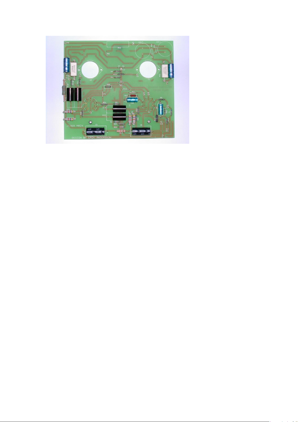
they align into the front chassis panel properly. Take time and care when fitting these.
See picture below for an idea of how the finished board should look.
Version 1.32
7
Power Supply PCB Assembly Instructions:
Insert and solder resistors R19, R20, R33, and R34, as well as diodes D1 to D4
observing their polarity. Solder R35 approximately 7mm above the board (this resistor
uses the Blue PTFE sleeves to mount it off the board as it can run warm in use).
Solder the terminal pins X15, X16, X17, and X18. Lastly, solder in the four
electrolytic caps C7, C8, C14, and C15 observing the correct polarity.
IT IS A GOOD IDEA TO THOROUGHLY CHECK THE CIRCUIT BOARDS FOR
ANY SOLDER JOINTS THAT HAVE BEEN MISSED OR LOOK DRY, AS THIS
COULD CAUSE A LOT OF PROBLEMS LATER.
Assembly of The Bottom Chassis:
Fit two of the mounting feet in the holes nearest the back of the chassis using an M4
screw and nut for each one - please note, the chassis panels may need drilling out to
allow the M4 screw to fit. Fit the loudspeaker terminals, two red and two black, on
each side of the chassis; for ease of wiring fit the black terminal(s) on the left of each
set when viewed from the front panel facing you. Note: current output transformers
now have three output pins instead of four. The forth pin that was a 2-Ohm tap is not
required and its removal has increased the frequency response of the output
transformer. For this reason it is a good idea to wire the speaker terminals for two
black and two red on each side, and join these to allow for bi-wiring and a better
sound. If the reds are on the inside of the two blacks, you can either wire for 4 and 8
ohm or just wire for 2 x 8 ohm. generally it will be found that for speakers down to 4
ohms or up to 14-16 ohms the 8 ohm tapping will prove to be the best sounding
output, but do try both and form your own opinion for this. Mount the three pairs of
RCA input sockets to the chassis with M3 screws and nuts; Note: the black sockets
are for the left channel and should be mounted at the top. Push in the mains switch,
and the mains socket with the fuse at the bottom.
When fitting any output transformer scrape the varnish off its underside, (top has the
pins on) and the paint from the chassis to ensure a good grounding in at least one
screw hole position. Now fit the transformers with M4 screws and nuts. The primary

Version 1.32
8
solder terminals on the output transformers (8 terminals) should point towards the
front of the amplifier.
Fit the mains transformer using the separate fixing kit supplied. Use the pad either
side, and the large metal disc on the top secured with the long M8 bolt and nut. It is
important to mount the mains transformer so that the wires point towards the front of
the amplifier to avoid inducing mains hum into the output transformers; leave a little
play in the length of its wires. Note: do not over-tighten the transformer as this may
crush the windings and destroy it –you have been warned!
If you are building the plus kit the new power transformers that we use are slightly
larger than before and will need to be mounted offset. with either one or two new
holes drilled to take the transformers. Below is a picture of a customers build who
moved the output transformers over slightly so the mains transformers would fit.
However, the offset positioning works just the same.
Finally, fit the complete power supply board using the three M3 stand-offs and M3
screws. There are three positions the board could go in, the easiest for wiring being
the middle position. The capacitors should be at the rear as shown in the picture
above.
Connect the loudspeaker terminals to the output transformers. The black speaker
terminal goes to B1 as well as ground; leave the transformer terminal B1 unsoldered
as the ground wire will be added later. The red terminals go the transformer
connections B3 and B4 (4 or 8 Ohms). Run these wires directly to the output
transformers. B1 is ground tap, (signal ground/earth and chassis ground/earth) B2 is
does not exist any more, B3 is the 4 ohm tap and B4 is the 8 ohm tap. (signal
ground/earth and chassis ground/earth)
After scratching off the paint surrounding the spare hole beside the power supply
fixings, secure the solder tag with an M3 screw and nut. Connect a wire from this tag
to the earth pin (marked E) on the mains input socket to become the earth tag. Wrap a
wire from the earth tag to pin X17 on the power supply board, but leave the earth tag
unsoldered as there are earth wires to be added later. Connect points 1 and 4 on the
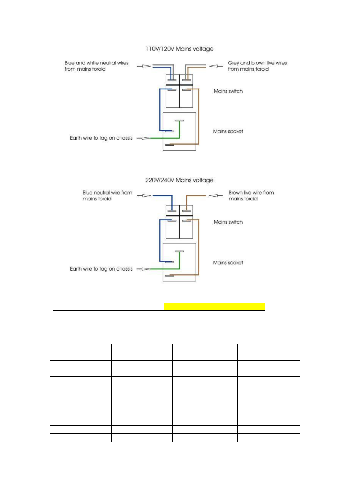
mains switch to the remaining pins on the mains inlet socket, as shown in figure 1
below:

Version 1.32
9
Figure 1. Mains socket switch connections
Figure 2 below shows the different windings on the mains transformer, not all of them
are used. Connect the mains transformer starting with the primary side that contains
two pairs of 115V windings.
For 220V/240V mains:
Solder the interior blue and brown wires together and fold them over to leave them
approximately 5cm in length. Seal them with a length of heat-shrink sleeving so that
no bare wires are exposed. The exterior brown and blue wires from the transformer
solder to points 2 and 5 on the mains switch as shown in the above diagram. Note: the
blue wire goes to the left, and the brown to the right when viewed from the front of
the amplifier. Cable-tie the four wires together to keep them tidy. All a.c. wires should
be twisted together in a reasonably tight twist (this helps avoid hum).
For 110V/120V mains:
Solder the two blue wires together as one pair, and the two brown wires together as
the other. Now solder the pairs to points 2 and 5 with the blue/white combination to
the left, and the brown/grey to the right when viewed from the front. Cable-tie the
four wires together to keep them tidy. Again all a.c. wires should be twisted together
in a reasonably tight twist (this helps avoid hum). In this case the brown/blue pairs
should be twisted together first and then the two twisted pairs twisted to each other
Version 1.32
10
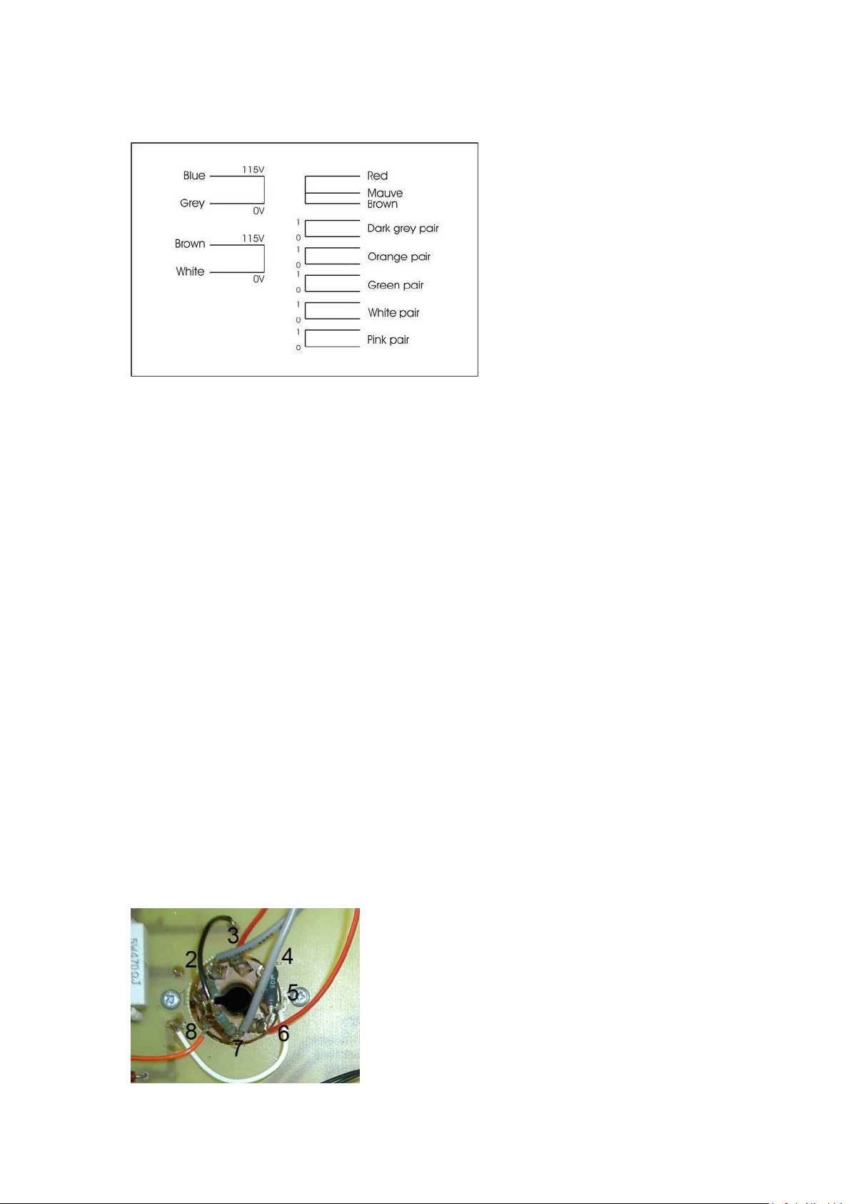
Figure 2. Mains transformer windings- REFER TO ADDENDUM NOTES
It is good practice to twist the mains wire blue brown together as this reduces hum. A
light twist aprox. every 1 - 1.5cm should be fine.
Blue
0V
White
X15 on PSU
Brown
120V
Red
Cut and Insulate
Black
X16 on PSU
Blue
0V
Brown
Cut and Insulate
Brown
120V
Yellow Pair
Small tube Heaters
Orange Pair
Cut, do not join
(Insulate)
Green Pair
Cut, do not join
(Insulate)
Mauve Pair
EL34 Heaters
Grey Pair
EL34 Heaters
Version 1.32
11
Original transformer layout.
The new transformer, although now larger, is designed for longer life.
Next connect the high-tension wires, which are enclosed in a fibre sleeves. The black
and white go to points X15 and X16 on the power supply board and supply 460V AC
from 240V AC mains. The other two wires brown and red are not used and need to be
cut back to approx 5cm and their ends covered with a small piece of heat shrink
tubing (supplied) to insulate them. It is not necessary to keep them in phase. The
brown and red wires are not used in this amplifier. The rest of the transformer wires
connect to the heaters when the amplifier is finally assembled, apart from the orange
and green pairs which are not used.
Mounting The Audio PCB In The Front Chassis Panel:
Before the Audio PCB’s are fitted, the octal valve bases for the EL34 power valves
must be attached to the front chassis panel using two M3 screws, an M3 nut, and a
12mm stand-off for each base. The two outer valve bases have the spacer on their
outer sides, and the two inner valve bases have their spacers on their inner most sides.
This is to support the PCBs properly. The valve bases mount directly under the
chassis panel with the valve orientation slot to the right of the amplifier when viewed
from the front top. Then, using the remaining 12mm stand-off’s fix the front row of
the PCB to the chassis using M3 countersunk screws in the appropriate holes.
The two PCB’s can now be fitted to the front chassis panel. For ease of fitting the
screws holding the pillars may need loosening (these are pre-mounted on some
chassis).

Version 1.32
12
The EL34 valve bases need connecting to the PCB’s. The valve base pins are
numbered 1 to 8. Warning: be sure to read the numbering correctly as it is easy to
make a mistake. Pin 1 must be linked to pin 8 on all four of the EL34 valve bases, and
extended to points X1 and X4 on the respective valve bases. For PP mode connect
points X13 and X3, to pin 5 on the respective valve bases, although for PSE mode
connect X2 instead of X13 so that X2 and X3 are connected to pin 5. The 105R
resistors (R53) must be soldered between pins 4 and 6 on each EL34 valve base. See
picture above
Before the volume pot can be fitted, the paint must be scratched away from the inside
of the larger hole in the front panel to enable it to be grounded properly. For volume
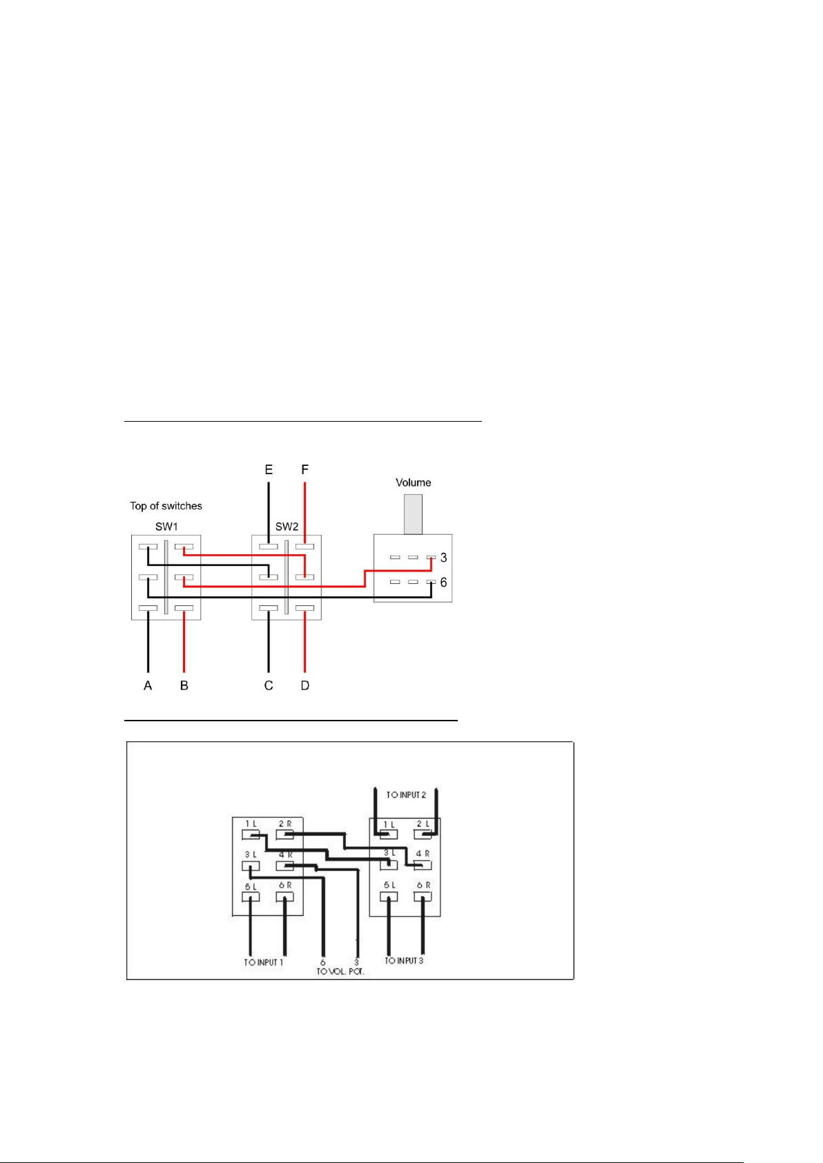
pot pin numbering please refer to figure 3 below. Connect pins 1 and 4 to ground on
the closest PCB (not both) at point X10. The PCB’s will be referred to as left and
right when looking from the front so that the left PCB drives the left channel, and
vice-versa. Terminal 2 on the volume pot connects to point X9 on the right PCB, and
terminal 5 connects to point X9 on the left PCB. Connect terminal 3 to input switch
S2 terminal 4, and finally connect terminal 6 on the volume pot to input switch S2
terminal 3. The volume knob can now be fitted using a small flat bladed screwdriver.
Figure 3. Volume pot numbering
The switches can now be fitted in the two smaller holes in the front panel, although
they will be connected up later.
Complete Assembly:
The side panels are fixed to the bottom rear chassis using six M3 screws, but first
scratch the paint on the hidden edge to make a continuous earth between all panels.
The front chassis is now ready to be fitted to the chassis using six M3 screws.
For PP mode connect point X18 on the power supply board, to points X5 on each of
the audio PCBs. If configuring for PSE mode with one power supply board, then wire
it for the PP configuration as above. However, if you are configuring for PSE mode
with the extra power supply board, then connect points X18 on each power supply
board to points X6 on the respective audio PCB.
The ground terminals X12 on the audio PCB’s connect to each of the output
transformers terminals B1; the ground connection for the speakers. The output

Version 1.32
13
transformer terminal B1 can now be soldered but be careful not to heat the tags for
prolonged periods as they are plastic and can melt.
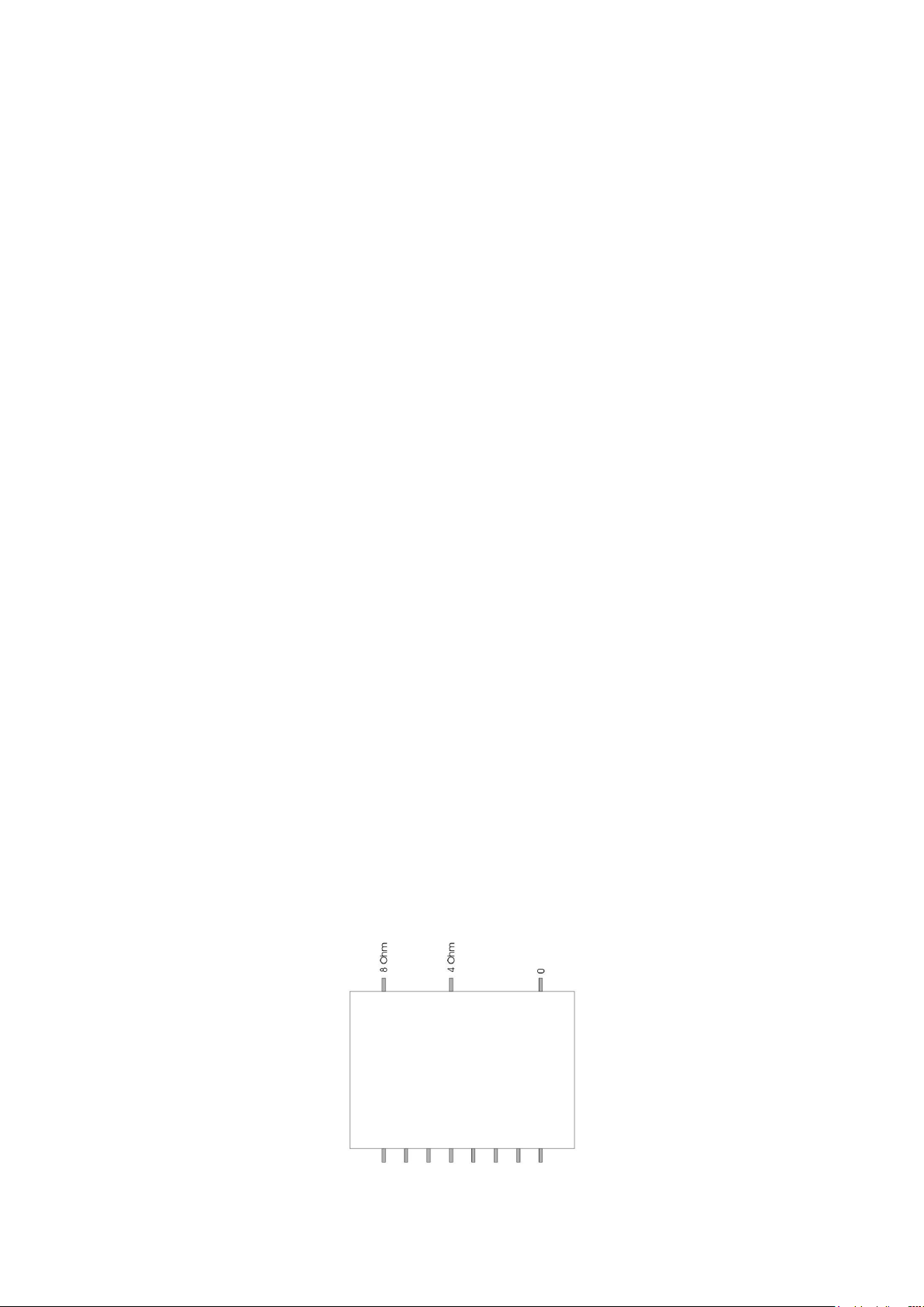
For clarity when looking at the output transformer, on the secondary winding side you
will see three pins, two are closer together and one is slightly further away. The one
slightly further away is the 0 ohm tapping, the middle is the 4 ohm tapping and the pin
closer to that is the 8 ohm tapping. Generally it is 0 --- 4 - 8 (see note at end)
A ground wire should also be connected between X12 on the right PCB to the earth
tag on the chassis. There should now be three wires to the earth tag; the main earth
from the inlet socket, the earth to point X17 on the power supply board, and the earth
to the right PCB. If they are all present then the earth tag can be soldered. This is
where you add the 22 ohm resistors. Two 22 ohm resistors are soldered in parallel,
one end joins to the earth tag on the chassis along with the main wire from the inlet
socket and the other two wires from the earth of the psu board and the earth from the
earth from the audio board join to the top of the 22 ohm resistors. This helps to reduce
hum.
To connect the heaters, link the two yellow wires from the mains transformer to
points X7 and X8 on the right PCB, the polarity does not matter. Now link points X7
and X8 on the right PCB to points X7 and X8 on the left PCB respectively, the
polarity of this connection is important to stop the heater windings from shorting if
both the earths are connected on the PCBs. If using two mains transformers from the
plus kit, connect the two yellow wires from each of the transformers to points 7 and
X8. Do not now use the bridging link between the two supplies.
To wire the EL34 heaters on the left PCB, the grey pair of wires from the mains toroid
are connected to pins 2 and 7 on V2. Then, two wires from pins 2 and 7 on V2 are
connected to pins 2 and 7 respectively on V1. For the right PCB the mauve pair of
wires are used and connected in the same way. The 54R9 resistors are used across the
EL34 heaters to reduce hum. Take a pair of 54R9 resistors and twist one end together
and solder to form a v-shape. The non joined ends are solder in parallel with the
heater wires to pins 2 and 7. The joined end is then connected to X12 via a wire link.
Do this for all 4 of the EL34 tubes. This forms a hum bucking circuit to reduce ac
mains generated hum.
The transformer windings that are not used should be cut off and/or insulated using
the heat shrink so that none of the windings are touching (they may be useful one
day). Do not join any of these windings together.
Version 1.32
14
Connect a wire from terminal B4 on the output transformers (this is the 8 ohm tap) , to
points X11 on the corresponding PCBs for the negative feedback connection. It is a
good idea to wire the right PCB first as this is further away and the wire will be
longer. Now cut the wire for the left PCB to the same length as the right to give the
same feedback path for each channel.
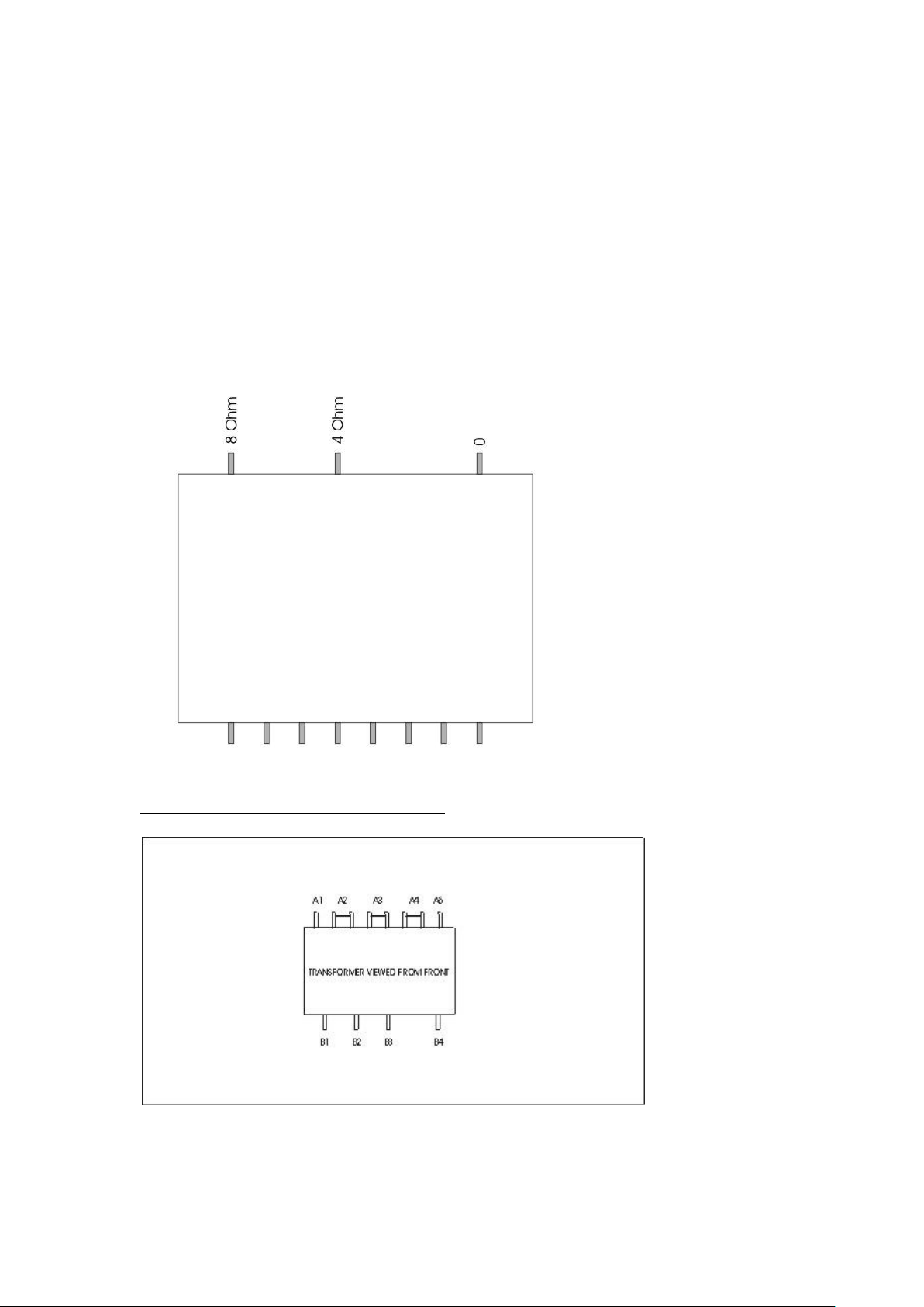
Configuring The Output Transformer For PP Mode:
Output transformer for Edison 60 power amplifier kits. Top view down with pins
closest to you. PLEASE NOTE : New transformers have slightly different end frames
so may need 2 extra holes drilling in the chassis to fit them properly!
Figure 4. Output transformer in PP mode
PLEASE NOTE - NEW TRANSFORMERS NO LONGER HAVE POSITION
B2 –2 OHM TAP –ONLY B4 = 8 OHM AND B3 = 4 OHM
SEE ADDENDUM NOTES

Version 1.32
15
Connect point X5 on each main PCB to its corresponding output transformer terminal
A3 (shown on figure 4 above).
For connecting the EL34 valve bases to the output transformers, starting with the left
PCB, link a wire from pin 3 on valve base V1, to terminal A1 on the output
transformer. Pin 6 on V1 (105R resistor), goes to the transformer terminal A2. Pin 3
on valve base V2 goes to pin A5, and pin 6 goes to terminal A4. The right PCB is
connected the same way.
The amplifier is now connected in ultra linear mode. For Triode mode connect pin 6,
to A1 (is B+ position) and A5 respectively on the output transformer. For Pentode
mode connect pin 6 from V1 and V2, to A3 on the output transformer.
Configuring The Output Transformer For PSE Mode:
Figure 5. 2.4K primary for maximum power triode connected
Figure 6. 3.6K primary for lower distortion with better low frequency, but lower
output.
Version 1.32
16
Connect up the links as shown in figure 5 or 6 above. Connect point X5 on each main
PCB to terminal A5 on the corresponding output transformers. On the left PCB
connect pin 3 on both V1 and V2, to A1 on the output transformer. Now connect the
two screen grid wires that come from pin 6 on each EL34, to A3 on the left
transformer. The EL34’s are now connected in parallel. The right channel in wired in
exactly the same way.
This is ultra-linear mode. For triode or pentode mode follow similar instructions for
the PP transformer connections.
Wiring The Input Connectors And Switches:
Cut the length of screened cable into three equal sections; they should be
approximately 470mm each. Now connect the centre wire of the screened cable to the
positive terminals as shown in figure 7 below.
Figure 7. Input switch connections from RCA sockets
Now fit the two input selector switches, and with the top panel upside down with the
switches and volume pot furthest away from you refer to the drawing above for wiring
up. Please note, the red and black wires shown are not those of the actual wires used

Version 1.32
17
but are simply to clarify wire positions and avoid confusion. (we would recommend
using red and black or differing colours to make identification easier). Also, the wires
marked A to F will be connected in the final assembly, and are the main input wires
from the RCA connectors on the rear of the amplifier
The volume knob can now be fitted using a small flat bladed screwdriver, unless you
have purchased the ‘Plus’ version of the kit when you need to put the volume knob on
at a later stage after the chrome top cover has been fitted.
Note for the Edison 60 Plus kit: An extra pair of 22 ohm resistors is supplied to
connect in parallel onto the tag with the others, this is for the split grounds
The screening, which is the ground connection for each input, should all be linked to
ground point X10 on the left PCB next to the volume pot. Finally, link a wire between
point X10 on the left PCB, to X10 on the right PCB.
Checklist:
The valve amplifier should now be fully assembled. Here is a list of items that should
be checked before the amplifier is plugged in:
1. Check that the earth connections have been soldered from the case to the
mains inlet. The resistance between the earth pin of the mains plug and the
chassis should be less than 0.5 ohms; generally the resistance of the test wires.
2. Turn the mains switch on and fit the fuse (which should be rated at 250 volts
3.15 amps). Measure the resistance between the earth pin in the mains plug
and the other two pins on the mains plug. This resistance should be infinite.
3. Check that the mains transformer wires are secure and wired to the correct
places.
4. Check that the output transformers are connected correctly to the speaker
terminals and to the audio PCB’s and valves.
5. Check that the power supply board is connected to each of the audio PCB’s.
6. A visual check is also a good idea to make sure that everything looks safe and
correctly connected.
The valve amplifier should not be switched on without the valves plugged in, and
without a sensible load connected to the speaker output terminals ( 8 or 4 ohm dummy
load of 20W, to the appropriate terminals, or loudspeakers but be careful that volume
is low) as this will damage the amplifier if not used. INSERT THE TUBES AT THIS
POINT.
THE AMPLIFIER CAN NOW BE PLUGGED IN AND TURNED ON.
The following nine voltages should be checked, using a Multimeter, to make sure that
the amplifier is operating safely. This should be done with the volume pot turned right

Version 1.32
18
down (anti-clockwise) so that the voltages are not affected by the output signal. The
voltages can be measured with the amplifier stood up on one end. Be careful here as
standing on its end is very unstable and catching an amp that is falling when switched
on could present a shock hazard. Prop the amp up and make sure that it is secure
before switching on.
WARNING: CARE MUST BE TAKEN WHEN CARRYING OUT THIS PART OF
THE PROCEDURE AS THERE ARE DANGEROUS VOLTAGES INSIDE THE
AMPLIFIER. IF UNSURE, PLEASE SEEK ASSISTANCE FROM A QUALIFIED
ENGINEER.
Please note that these voltages may vary slightly due to variations in the mains
supply, and valve and component tolerances. Note: a variation of approximately 10%
is acceptable without any detrimental problems.
1. On the power supply PCB measure the voltage between X17 (ground), and
X18. For PSE mode this should be approximately 460V- 490V DC. For Push
Pull this should be approximately 460V DC. Depending on mains voltage.
2. The Cathode bias voltage (pin 8) for each EL34 should be approximately 35V
DC. This is measured across the 470R 7W resistors, and is relatively important
to prove current flow through the valve.
3. The anode voltage for each EL34 should be approximately 430V- 450V DC.
This is measured between ground and pin 3 of each EL34.
4. The smaller tubes can also be checked top and bottom for bias voltages.
Final Assembly:
Disconnect from the mains.
The last two feet can be fitted to the bottom cover plate using M4 screws and
nuts. The holes in some of the cover plates will need drilling out to fit the M4 screw.
If using the larger feet, for the standard feet it will be fine.
Last of all the top cover plate must be fitted. The front of the panel tucks under the
front chassis panel and is secured by three M3 screws at the rear. If the top cover does
not tuck under the front panel the corners may need trimming off as shown in figure 8
below.

Version 1.32
19
Figure 8. Trimming the top cover panel (side cutters will do)
Please note that the amplifier is at all times pure Class-A, and as such will run
reasonably hot.
We hope that you enjoy building your kit!!!
If you have any technical queries or construction problems please email
This handbook may contain mistakes and printing errors. The information in this
handbook is regularly checked and corrections made in the next issue. We accept no
liability for technical mistakes or printing errors, or their consequences.
Upgrade options
Stainless Steel hex head screw upgrade
The stainless steel hex head screws - 16 in total are designed to replace the standard
zinc pan pozi screws used to hold the valve/tube bases to the chassis and also the 8
screws that are on the top stainless steel top plate.
The 8 screws that hold the valve/tubes bases down should be used in conjunction with
an M3 washer for optimum holding.
Tantalum Resistor Upgrade
These exotic resistors sound less dry than metal films and they do not emphasize any
particular frequency range. They sound more natural, more musical. They work
extremely well in Edison kit tube amplifiers. Most customers, who have tried the
tantalums, say that they would never go back to the common metal film type resistors.
These have a 1% tolerance.
Care must be taken in their use and when bending component legs, do not bend too
close to the resistors body. We recommend using a pair of long nose pliers closest to
the body and the bend made after the pliers.
Version 1.32
20
The resistors supplied with this upgrade kit are as follows :-
1 x 390R resistor (R25)
1 x 470R resistor (R27)
7 x 1K resistors (R9,R10,R11,R11b,R12,R21,R22)
These replace the standard resistors that are supplied with your standard or plus kit.
The resistors listed above form the audio path within your amp. There are 2 packs (1
per board) giving a total of 18 Resistors.
Although we recommend the use of silver solder with these resistors, we would
strongly advise to use the same solder across the whole circuit board. So if you are
using a ROHS lead free solder, use that throughout the amp, likewise if you have used
a silver solder on the boards then use that throughout your build to maintain sonic
consistency and electrical stability.
Silver Night Format output transformer
The silver Night output transformer designed for the Edison 60 power amplifier kits.
Top view down with pins closest to you.
PLEASE NOTE : This transformer uses the same grain orientated silicon steel M6
grade, high purity double insulated copper wire and extremely high quality interleave
tape with the same winding format as the Silver Night transformer, but in a final
layout configuration for the Edison kit. The output transformer is the heart of the
amplifier and what controls its final sound. These transformers offer superb fluidity
and with the Edison, frequency response curves from 10hz to 45Khz +/-3db.
The format follows the standard Edison kit layout
B4 B2 B1
A5 A4-A4 A3-A3 A2-A2 A1
8 ohm 4 ohm 0 ohm
Anode................................B+
This manual suits for next models
1
Other Audion Amplifier manuals


