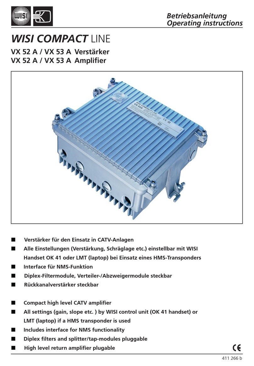
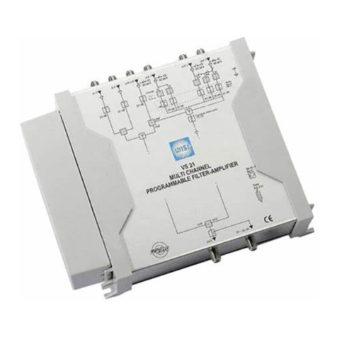
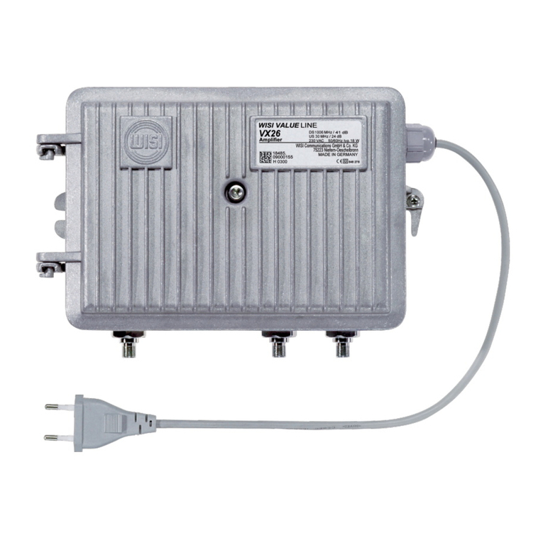
Wisi VX 56 B Series User manual

Operating instructions
© WISI Communications GmbH & Co. KG www.wisi.de
Stay up to date
For more information on your device, please visit our support web-
site at wisiconnect.tv and browse to:
Please read the user instructions before using the equipment.
WISI COMPACT LINE
VX 56 B / VX 57 B series
RF amplifier - dual output stage
417820-c (05/2020)
Knowledge Base > VX series > Products > VX 56 B / VX 57 B
http://bit.ly/wisivx56_57b

WISI COMPACT LINE
Operating instructions
© WISI Communications GmbH & Co. KG www.wisi.de-2-
VX 56 B / VX 57 B series
RF amplifier - dual output stage
CE declaration of conformity
Please find the declaration of conformity at our website:
https://www.wisi.de/en/communications/service/download-area/
Then navigate through “CE Declarations of Conformity” and select the document link
corresponding to your device.
Document revision information:
Date Doc.
rev.
Document changes
20.05.2020 cDocument structure rearranged;
Reviewed sections on ALSC (4.5) and HMS transponder (3.5);
Added description of the HFC updater app (3.4);
FW v1.0.0.84 / HFC manager+ v2.5.13 / HFC updater v0.4.5
09.01.2020 bIntroducing ECO-Mode; Corrections for spectral data table with
VX 58 B; product range VT 21 updated
FW v1.0.0.68 / HFC manager+ v2.2.0
24.05.2019 a Separation of VX 56 B / VX 57 B from the VX 5x B series
Changeover to new layout and outline
VX 58 B: Signal monitoring, ALSC, auto-alignment
FW v1.0.0.64 / HFC manager v2.1.8
This document was split off from the common manual for the VX 5x B series (414874).

WISI COMPACT LINE
© WISI Communications GmbH & Co. KG www.wisi.de-3-
VX 56 B / VX 57 B series
RF amplifier - dual output stage
Operating instructions
Contents
1 Safety and warning notes ............................................................................ 4
1.1 ESD protection ........................................................................................... 4
1.2 Electrical safety .......................................................................................... 4
2 Device overview ............................................................................................ 5
2.1 Outer features and accesories .................................................................... 5
2.2 Remote powering ...................................................................................... 6
2.3 Spectral monitoring module: VX 58 B ........................................................ 7
3 Control interfaces .......................................................................................... 9
3.1 Configuration via handset OH 41 ............................................................... 9
3.2 Bluetooth interface basics ........................................................................ 10
3.3 Device control using HFC manager+ ......................................................... 11
3.4 Firmware updates and recovery using HFC updater .................................. 12
3.5 Remote control via HMS transponder VT 52 B .......................................... 16
3.6 Remote control via FSK receiver module VT 21 ......................................... 20
4 Configuration of signal transmission ........................................................ 22
4.1 Basic downstream configuration .............................................................. 22
4.2 Basic upstream configuration ................................................................... 25
4.3 Spectral monitoring ................................................................................. 27
4.4 Auto-alignment ....................................................................................... 29
4.5 Automatic level and slope control (ALSC) ................................................. 31
4.6 ECO-Mode .............................................................................................. 34
5 Functional diagram ...................................................................................... 35
6 Service and support: wisiconnect.tv .......................................................... 36
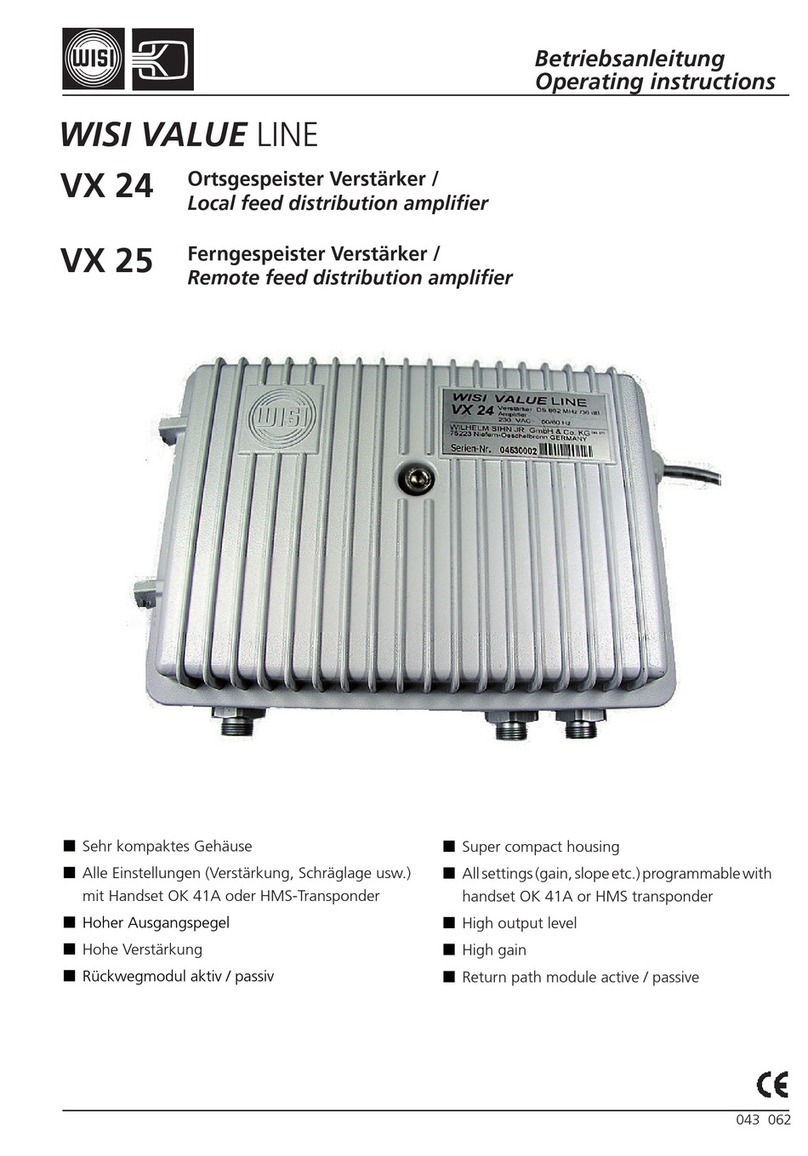
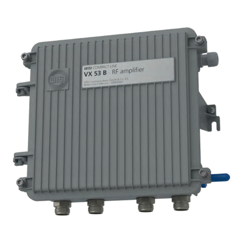
Operating instructions:
VX 56 B / VX 57 B series
RF amplifier (dual output stage)
WISI COMPACT LINE
Operating instructions
© WISI Communications GmbH & Co. KG www.wisi.de-4-
VX 56 B / VX 57 B series
RF amplifier - dual output stage
1 Safety and warning notes
This equipment must be installed and operated by qualified and trained
personnel only.
Please familiarize with the instructions before start-up.
Carefully inspect the device for any obvious damage. If it appears to have been dama-
ged, contact your WISI representative.
Do not use any equipment with noticeable damage!
1.1 ESD protection
This product contains electrostatic sensitive components.
These parts can be damaged or effectively destroyed by electrostatic di-
scharge (ESD) during unpacking, installation, removal, storage, or shipment
if incorrectly handled.
Please note that discharge might go unnoticed by a user.
Always take common antistatic precautions when handling the equipment.
1.2 Electrical safety
Risk of bodily injury from electric shock!
Failure to adhere to these instructions could result in personal injury and/or
damage to electrical components.
• The equipment must be grounded in accordance to local and national electrical
standards.
• The device is started up immediately when the power plug is inserted into the
mains socket. To turn off the power supply, the plug must be removed from the
socket. Never pull at the cable.
• The mains socket should be easily accessible. In the event of operational error, the
plug must be immediately removed from the socket.
• The power supply partition of the equipment as well as all coaxial interfaces carry-
ing remote power feeding contain dangerous voltages. All service or maintenance
work should be carried out by qualified personnel who can get assistance by con-
tacting the manufacturer’s agent.

WISI COMPACT LINE
© WISI Communications GmbH & Co. KG www.wisi.de-5-
VX 56 B / VX 57 B series
RF amplifier - dual output stage
Operating instructions
2 Device overview
2.1 Outer features and accesories
Lid reten�on screws
(2 +0.5 Nm)
Mains input
Bluetooth antenna
WISI LB 01
RF output 1
RF output 2
RF loop-through
RF input
Outer overview on the housing features of the amplifier.
NOTE: Interface configuration may vary.
Housing accessories:
WISI type Description Notes
XE 29 Cabling kit for remote power insertion for VX 57 B only
ZG 27 PG 11 case connection for MK 15 cable
ZG 28 PG 11 adapter, F female
ZG 35 A PG 11 adapter, 3.5/12 female pre-equipped in VX 57 B
CC, VX 56 B CH01, VX 57
B CH01
LB 01 Bluetooth antenna for PG 11 pre-equipped

WISI COMPACT LINE
Operating instructions
© WISI Communications GmbH & Co. KG www.wisi.de-6-
VX 56 B / VX 57 B series
RF amplifier - dual output stage
2.2 Remote powering
Functional diagram of the power supply circuitry.
Spare fuses Fuse removal tool
(VX 57 B only) Socket for
Remote power insertion
Features around the power supply compartment.

WISI COMPACT LINE
© WISI Communications GmbH & Co. KG www.wisi.de-7-
VX 56 B / VX 57 B series
RF amplifier - dual output stage
Operating instructions
F1
Fuse for RF input
F2
Fuse for RF loop-through
F3
Fuse for RF output 2
F4
Fuse for RF output 1
RF
input
RF loop-
through
RF
output 1
RF
output 2
Position of the fuse sockets inside of the amplifier.
2.3 Spectral monitoring module: VX 58 B
(9) Signal
monitoring
module
Position of the signal monitoring socket for the WISI VX 58 B module.

WISI COMPACT LINE
Operating instructions
© WISI Communications GmbH & Co. KG www.wisi.de-8-
VX 56 B / VX 57 B series
RF amplifier - dual output stage
The optional spectral monitoring module WISI VX 58 B provides a spectrally resolved
level measurement. VX 56 B / VX 57 B leverages this for three main functionalities:
1. Spectral monitoring of the output downstream signal (section 4.3),
2. Auto-alignment of downstream and upstream signal paths (section 4.4), and
3. Automatic level and slope control (ALSC) / pilot regulation (section 4.5).
NOTE on the reference point for the measurements:
The measurement signal is tapped from the output amplifier stage of RF channel 2
(see diagram in section 4.1).
All levels are monitored for RF output 2, so keep in mind that RF output 1 can deviate
if an asymetric output configuration module (see section 4.1.1) is plugged or if the
output 1 attenuator (see section 4.1.4) differs from 0 dB.

WISI COMPACT LINE
© WISI Communications GmbH & Co. KG www.wisi.de-9-
VX 56 B / VX 57 B series
RF amplifier - dual output stage
Operating instructions
3 Control interfaces
3.1 Configuration via handset OH 41
NOTE: The VX 56 B / VX 57 B only works with handsets OK 41 A and OH 41. OK 41 is outdated and not
compatible.
Socket for
Handset control
Position of the handset connector inside the amplifier.
Handset basics
Parameter menu
5656 keys Select parameter
44key Open parameter sub-menu
33key Back
Parameter sub-menu
3434 keys Select value to be changed
Cursor blinks under the active digit
5656 keys Change the value
Saving: after completion of all settings, press the key 3 3 or 4 4 for leaving the value
field. The settings are saved now.
NOTE: If not saved, settings are lost as soon as the handset is disconnected.

WISI COMPACT LINE
Operating instructions
© WISI Communications GmbH & Co. KG www.wisi.de-10-
VX 56 B / VX 57 B series
RF amplifier - dual output stage
3.2 Bluetooth interface basics
The management interface of the amplifier can be accessed using the bluetooth low-
energy (BLE) wireless technology. The bluetooth antenna enables the radio connection
to a smart phone or tablet.
The Android app WISI HFC Manager+ provides the GUI for the configuration of the
fiber node, whereas the WISI HFC updater brings firmware update and recovery func-
tions.
Bluetooth
activation LED
Bluetooth activation button
Effective only if „BT function“ is set to „Timeout“
WISI LB 01
Bluetooth antenna
Position of the bluetooth elements on the right of the amplifier.
Multilevel security implementation
There are three security levels implemented to prevent the device from unauthorized
access. The figure below shows the security levels and the according security mecha-
nism.

WISI COMPACT LINE
© WISI Communications GmbH & Co. KG www.wisi.de-11-
VX 56 B / VX 57 B series
RF amplifier - dual output stage
Operating instructions
Level 1: Button activation
The BT activation button inside the device (see figure above) opens the bluetooth
interface for connections. The button activation behaviour can be modified via the
handset interface (see section 5.2.2, fig. “Bluetooth”).
Level 2: Key authentication
The connecting mobile device needs to authenticate with a configurable password.
The Initial password is „565835“.
NOTE: Please change the initial password during the first setup in order to avoid un-
authorized access!
Level 3: Access control list (ACL)
Once paired, a BT device can be put into the access list. If ACL restriction is enabled,
the node will only allow clients within this list to connect.
3.3 Device control using HFC manager+
Please install the WISI BLE app from the Google Play Store:
https://play.google.com/store/apps/details?id=de.wisi.hfc_manager
When starting up the application, the device scan listing will populate with all surroun-
ding Bluetooth devices:
Device scan list (example).

WISI COMPACT LINE
Operating instructions
© WISI Communications GmbH & Co. KG www.wisi.de-12-
VX 56 B / VX 57 B series
RF amplifier - dual output stage
Select your device and wait for the connection to be established. Once connected, the
Bluetooth logo in the upper right corner will show the connection quality.
The start screen provides a selected set of device details:
Device overview (example).
The menu is available through the blue logo in the upper left corner or by swiping
from the left screen edge:
App menu overview (example).
3.4 Firmware updates and recovery using HFC updater
You can use the WISI HFC updater app to update the amplifier‘s firmware via a blue-
tooth connection.
3.4.1 Basic update procedure
1. When starting up the application, the device scan listing will populate with the
active Bluetooth devices nearby. The list is sorted by signal strength. Tapping the
search button on the lower right will initiate another scan.

WISI COMPACT LINE
© WISI Communications GmbH & Co. KG www.wisi.de-13-
VX 56 B / VX 57 B series
RF amplifier - dual output stage
Operating instructions
Device scan list (example)
2. Tap on the device you want to operate on. After a few seconds of loading time,
the device inventory will show up.
Device inventory (example)
3. If there is an update available for your device, the SW version will be highlighted.
4. The „Update“ button opens the update screen. This will only be available, if the
particular device does support FW updates via bluetooth.

WISI COMPACT LINE
Operating instructions
© WISI Communications GmbH & Co. KG www.wisi.de-14-
VX 56 B / VX 57 B series
RF amplifier - dual output stage
Update screen (example)
5. Double check the firmware versions. Maybe you want to check the release notes
on our support website wisiconnect.tv.
NOTE: Although all user settings will be restored after the update, signal transmission
will be affected temporarily during the update process!
6. If sure to proceed, start the update process by tapping "start update“. The firm-
ware upload can take up to 10 minutes. Avoid disturbing the bluetooth connec-
tion during the update process: Leave the HFC updater app active on the mobile
device, do not make or take calls, and stay within the reach of the bluetooth
connection.
Update progress (example)
7. Once finished, the app will show a message on the outcome of the update pro-
cess.

WISI COMPACT LINE
© WISI Communications GmbH & Co. KG www.wisi.de-15-
VX 56 B / VX 57 B series
RF amplifier - dual output stage
Operating instructions
Confirmation message (example)
8. Depending on your device settings, you may have to re-activate the bluetooth
interface using the bluetooth button. Then, reconnect to the amplifier and verify
the installed firmware version.
3.4.2 Recovery of devices stuck in bootloader
Mainly due to adverse bluetooth radio conditions during update operations, you may
find an amplifier stuck in bootloader mode. A bootloader device can be identified by
a modified device name in the scan list.
Found device in bootloader mode (example)
Typically, restarting the basic update procedure will automatically find an applicable
firmware and accomplish the update task.
Expert mode:
In case the HFC updater fails to identify the device type correctly, the "expert" mode
can help recover the unit, either by choosing one of the included firmware images
from the "select file" list or by importing an update file from your mobile storage.
IMPORTANT NOTES on updates in expert mode:
• Applying an inappropriate firmware update can lead to severe malfunctions!
• Be sure to choose the correct device type from the "select file" list!
• Use only update files from trusted sources!
• Never change any file name or contents of update files!

WISI COMPACT LINE
Operating instructions
© WISI Communications GmbH & Co. KG www.wisi.de-16-
VX 56 B / VX 57 B series
RF amplifier - dual output stage
Expert mode of the update screen
3.5 Remote control via HMS transponder VT 52 B
WISI VT 52 B
HMS transponder module
in socket (8)
Status LED
Reset button
Press to reboot transponder
Position of the transponder socket for the WISI VT 52 B.

WISI COMPACT LINE
© WISI Communications GmbH & Co. KG www.wisi.de-17-
VX 56 B / VX 57 B series
RF amplifier - dual output stage
Operating instructions
3.5.1 Firmware compatibility
Support for the HMS remote control of VX 56 B / VX 57 B via VT 52 B is implemented
since the following firmware revisions:
• VX 56 B / VX 57 B: v1.0.0.64 or newer
• VT 52 B: L03.01.01.000 or newer
HMS inventory data is supported since
• VX 56 B / VX 57 B: v1.0.0.84 or newer
• VT 52 B: L03.01.02.000 or newer
For compatibility reasons, please make sure that both products are operating on a
suitable firmware revision. See section 3.4 of this manual and/or the VT 52 B docu-
mentation (e.g. http://bit.ly/wisivt52b) for more details about firmware updates.
3.5.2 Basic transponder setup
We recommend the following steps for the establishment of an HMS connection to
the VX 56 B / VX 57 B.
1. We assume that the amplifier is properly configured for RF transmission in down-
and upstream, e.g. according to sections 4.1 and 4.2, and that the transponder
module is mounted in the designated slot as shown above. An HMTS (e.g. Cisco
Phoenix) must be connected to the HFC line and properly configured for the regis-
tration of new transponders.
2. After initialization of the amplifier‘s on-board communication (can take up to 30
seconds), the remote module type will be shown on the user interface. The
status LED will shine red.
3. Set the HMS downstream frequency to the channel frequency the transponder
is ment to listen to.
4. Make sure the HMS downstream level is in the appropriate range (45...75 dBµV).
NOTE: It may take up to 30 seconds until the monitoring values in the user interface
are updated.
5. The HMS registration status will change from „noHMSSignal“ to
„validHMSSignal“. The upstream frequency is set by the HMTS („validChnlDesc“).
6. Depending on the configuration of the registration interval in your HMTS, it might
take some minutes until the the HMTS starts the registration process (HMS regis-
tration status „startREG“ / “sendREGREQ“). During the registration procedure,
the status LED will be blinking red.

WISI COMPACT LINE
Operating instructions
© WISI Communications GmbH & Co. KG www.wisi.de-18-
VX 56 B / VX 57 B series
RF amplifier - dual output stage
NOTE: If registration fails to start, maybe the transponder‘s HMS upstream level
needs to be adjusted.
7. The IP address assignment can vary depending on the configuration of your HMS
system. You can identify the transponder by its HMS MAC address in the device
table of the HMTS in order to assign an IP address remotely, or set an appropriate
HMS IP address in the local user interface.
8. Once the HMS registration is successfully finished, the status LED will turn off and
the HMS registration status is „successREG“. You can now access the LR 44 via
SNMP / HMS.
Remote module type
HFC manager: HMS > HMS Module read-only:
[no module plugged] /
[VT 52 B (HMS)]
Handset: Remote-Modul > Module Type >
SNMP: OID 1.3.6.1.4.1.5591.1.3.1.3.0
(commonModelNumber)
HMS downstream frequency
HFC manager: HMS > DS Freq. > 48...162 MHz
0.1 MHz steps
Handset: Remote-Modul > DS Freq >
SNMP: OID 1.3.6.1.4.1.5591.1.3.5.2.0
(commonForwardPathFrequency)
HMS downstream level
HFC manager: HMS > DS Lvl. read-only:
15.2...99.9 dBµV
0.1 dB steps
Handset: Remote-Modul > DS Level >
SNMP: OID 1.3.6.1.4.1.5591.1.3.5.4.0
(commonForwardPathReceiveLevel)
HMS registration status
HFC manager: HMS > Reg. State read-only:
[noHMSSignal] /
[validHMSSignal] /
[validChnlDesc] /
[startREG] /
[sendREGREQ] /
[successREG]
Handset: Remote-Modul > Reg.State >
SNMP: OID 1.3.6.1.4.1.7465.20.2.3.2.10.0
(hfcRegistrationState)

WISI COMPACT LINE
© WISI Communications GmbH & Co. KG www.wisi.de-19-
VX 56 B / VX 57 B series
RF amplifier - dual output stage
Operating instructions
HMS upstream level
HFC manager: HMS > US Lvl. > default: 90 dBµV
0.1 dB steps
Handset: Remote-Modul > US Level >
SNMP: OID 1.3.6.1.4.1.5591.1.3.5.3.0
(commonProvisionedReturnPowerLevel)
HMS MAC address
HFC manager: HMS > MAC Address read-only:
12-digits hexadecimal
Handset: Remote-Modul > MAC Address >
SNMP: OID 1.3.6.1.4.1.5591.1.3.2.7.0
(commonPhysAddress)
HMS IP address
HFC manager: HMS > IP Address XXX.XXX.XXX.XXX
Handset: Remote-Modul > IP Address >
SNMP: OID: 1.3.6.1.4.1.5591.1.3.1.9.0
(commonNetworkAddress)
3.5.3 HMS inventory data
For the remote identification of a network element the following parameters are of
special interest.
• You can take the HMS MAC address of a transponder to your deployment docu-
mentation for later reference.
• You can store user-defined codes in the "device name" and/or "device location"
parameters on the amplifier.
NOTE: HMS inventory data is supported since VX 56 B / VX 57 B FW v1.0.0.84 and VT
52 B FW L03.01.02.000.
HMS MAC address
HFC manager: HMS > MAC Address read-only:
12 digits, hexadecimal
Handset: Remote-Modul > MAC Address >
SNMP: OID 1.3.6.1.4.1.5591.1.3.2.7.0
(commonPhysAddress)

WISI COMPACT LINE
Operating instructions
© WISI Communications GmbH & Co. KG www.wisi.de-20-
VX 56 B / VX 57 B series
RF amplifier - dual output stage
Device name
HFC manager: HMS > Name 16 digits,
alphanumerical
SNMP: OID 1.3.6.1.2.1.1.5
(sysName)
Device location
HFC manager: HMS > Location 44 digits,
alphanumerical
SNMP: OID 1.3.6.1.2.1.1.6
(sysLocation)
3.6 Remote control via FSK receiver module VT 21
WISI VT 21
FSK receiver module
in socket (11)
Position of the FSK-receiver socket for the WISI VT 21 (Fostra-F-compatible)
Other manuals for VX 56 B Series
1
This manual suits for next models
3
Table of contents
Other Wisi Amplifier manuals

Wisi
Wisi VX 52 B Series User manual

Wisi
Wisi VS 21 User manual

Wisi
Wisi VX 56 B Series User manual

Wisi
Wisi MIDI Series User manual

Wisi
Wisi MIDI Series User manual

Wisi
Wisi VX 52 B Series User manual

Wisi
Wisi VX 29 B Series User manual

Wisi
Wisi VX 52 User manual

Wisi
Wisi OM12 Series User manual

Wisi
Wisi VX 12 V 2220 User manual