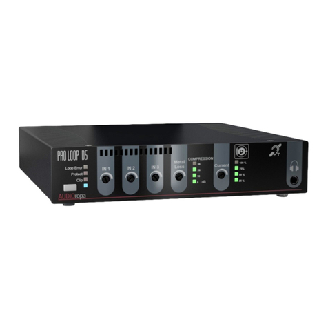
AUDIOropa PROLOOP C User manual

DE
EN Operation Instructions
FR Mode d’emploi
NL Gebruiksaanwijzing
Seite 2
Pagina 26
Page 18
Page 10
Bedienungsanleitung
PROLOOP C
Ringschleifenverstärker
Loop amplifier
Amplificateur à boucle magnétique
Ringlusversterker

2 Deutsch
1. Übersicht der Anschlüsse und Bedienelemente
1 2 3 4 5 6 7 8
9 10 11 12 13
1.1 Frontseite
1 Anzeige Eingangssignal
2 Anzeige Ringschleife
3 Regler zum Einstellen der jeweiligen Eingangs-Empfindlichkeit
4 Treble = Höhenregler
5 Regler zum Einstellen des Schleifenstroms
6 Anzeige Spannungsversorgung
7 Kopfhörerausgang
8 Lautstärkeregelung für Kopfhörerausgang
1.2 Rückseite
9 Netzanschluss 230 V / 50 Hz
10 Schraubklemmen für den Anschluss der Ringschleife
11 Line OUT - Monitorausgang
12 Line IN - Eingang für Geräte mit Line-Pegel (25 mV - 4 V)
13 Line IN - Eingänge mit symmetrischen XLR Buchsen.
Per Jumper wählbare Eingangs-Empfindlichkeit zwischen 0,5 mV - 100 mV für
Mikrofone und 25 mV - 4 V für Geräte mit Line-Pegel. Eine Phantomspannung ist
zuschaltbar.

Deutsch 3
Wir beglückwünschen Sie zum Erwerb Ihres Ringschleifenverstärkers PROLOOP C!
Mit dieser Wahl haben Sie sich für ein Produkt entschieden, welches ansprechendes De-
sign und technische Leistungsstärke gekonnt vereint.
Dieses Handbuch beinhaltet die genaue Funktion und Anwendung des Verstärkers.
Bitte lesen Sie die Bedienungsanleitung aufmerksam durch, bevor Sie den Verstärker ein-
setzen. Wir behalten uns außerdem das Recht vor, im Sinne von Produktentwicklungen
Änderungen vorzunehmen.
1.3 Standard-Lieferumfang
Folgende Teile sind im Lieferumfang enthalten:
- Ringschleifenverstärker PROLOOP C
- Netzkabel
- 2 Montagewinkel
- Bedienungsanleitung
- Garantiekarte
Sollten Teile fehlen, wenden Sie sich bitte an Ihren Fachhändler oder direkt an den Hersteller.
2. Hinweise für den sicheren Gebrauch
Das Gerät entspricht allen erforderlichen Richtlinien der EU und ist deshalb mit CE gekenn-
zeichnet.
Damit Sie lange Freude an Ihrem Gerät haben, beachten Sie bitte nachfolgende Hinweise:
Wichtige Hinweise
• Um Unfälle und Verletzungen durch elektrischen Schlag zu vermeiden,
stellen Sie keine mit Flüssigkeit gefüllten Gegenstände, z.B. Vasen
auf das Gerät.
• Ziehen Sie den Netzstecker niemals am Kabel aus der Steckdose,
erfassen Sie stets den ganzen Stecker.
• Betreiben Sie das Gerät nicht in der Nähe von Wärmequellen oder
in Räumen mit hoher Luftfeuchtigkeit. (Einsatztemperaturbereich
0-40°C)
• Die Lüftungsöffnungen dürfen nicht abgedeckt werden, damit die
entstehende Wärme durch Luftzirkulation abgegeben werden kann.
• Das Gerät kann je nach Beanspruchung am Kühlkörper und an
den Lüftungsschlitzen hohe Temperaturen entwickeln.
Vorsicht vor versehentlicher Berührung – Verbrennungsgefahr !!!

4 Deutsch
Wichtige Hinweise
Benutzen Sie das Gerät nicht:
• wenn Netzkabel oder Netzstecker defekt oder beschädigt sind
• wenn das Gerät nicht ordnungsgemäß funktioniert oder defekt ist
• wenn das Gerät heruntergefallen oder auf andere Weise beschädigt
ist.
• Vor der Reinigung immer den Netzstecker ziehen.
• Verwenden Sie zum Reinigen nur ein trockenes Tuch - niemals
Chemikalien oder Wasser.
• Geben Sie das Gerät in jedem Fall zur Reparatur nur in eine
Fachwerkstatt.
3. Einsatzmöglichkeiten
Der PROLOOP C Verstärker wurde für den Einsatz in professionellen Bereichen ausge-
legt, in denen hohe Beständigkeit und sicherer Betrieb unabdingbar sind. Der 100 % kurz-
schlussfeste Verstärker mit programmierbaren, symmetrischen XLR-Eingängen und sehr
stabiler Ausgangsleistung erfüllt diese Anforderungen. Die AGC-Funktion dämpft den Si-
gnalpegel stetiger Signale, wie Oszillation und Sinuskurven auf -10 dB und sorgt damit für
eine konstante Feldstärke und einen stabilen Klang.
Induktive Höranlagen werden für unterschiedliche Anwendungen eingesetzt, z.B. als Hilfs-
mittel für Hörgeschädigte in Kirchen, Theatern, Kinos, Warte- und Aufenthaltsräumen, als
Dolmetscheranlagen, bei Vorträgen in Museen, Ausstellungen usw.
3.1 Funktionsweise
Der Ringschleifenverstärker erzeugt ein elektromagnetisches Wechselfeld um das Ring-
schleifenkabel. Die Ringschleife besteht aus einem isolierten Draht, der überwiegend ein-
mal (oder doppelt) entlang den Seiten des Raumes ausgelegt wird.
Wenn der Hörgeräteträger sein Hörgerät auf die „T-Position“ stellt, wird in der T-Spule eine
Spannung induziert. Diese steht im Verhältnis zum Eingangssignal des Verstärkers. Die
Signale werden nun vom Hörgerät verstärkt und in Schall umgewandelt. Das elektromag-
netische Wechselfeld innerhalb der Ringschleife erlaubt es dem Hörgeräteträger, sich frei
im Raum zu bewegen und die Sprach- bzw. Musiksignale in einem guten, angenehmen
Klang zu empfangen.

Deutsch 5
3.2 Leistungsmerkmale des Ringschleifenverstärkers PROLOOP C
• Für Flächen bis 170 m2
• Ausgangsstrom 4 A RMS
• Kurzschlussfest
• Automatisch rücksetzbare Sicherung
• 2 programmierbare, symmetrische XLR Eingänge und 1 Cinch Line IN Eingang
• Line IN oder Mikrofon IN mit Phantomspannung können für Line IN 1 und 2 separat
eingestellt werden
• Hohe Sicherheit dank der durch Ausgangsspannung und Strom kontrollierten AGC,
welche Rückkopplungs-Probleme verringert
• Kopfhöreranschluss in der Gehäusefront und Line OUT Cinch-Ausgang auf der Rückseite.
• Hochtonregler zum Ausgleich von Hochfrequenzverlusten durch Armierungen in Wand
und Boden
4. Installation
Das Gerät arbeitet mit lebensgefährlicher Netzspannung von 230 V.
Nehmen Sie deshalb niemals selbst Eingriffe am Gerät vor und
stecken Sie nichts durch die Lüftungsöffnungen! Es besteht die
Gefahr eines elektrischen Schlages!
Tipps
1. Bevor Sie mit der Installation beginnen, sollte unbedingt überprüft
werden, ob an dem dafür vorgesehenen Ort magnetische Störungen
auftreten.
Diese können den Betrieb beeinträchtigen oder sogar unmöglich
machen. Störungen können z.B. von Transformatoren, Stromleitungen,
Armierungen im Stahlbeton oder durch eine Fußbodenheizung verur-
sacht werden.
2. Sollte die Ringleitung in einem Rohr verlegt werden, ist darauf zu achten,
dass dieses aus Kunststoff besteht.
3. Verlegen Sie keine Eingangssignalkabel parallel zur Ringschleifenleitung.
4. Vermeiden Sie dynamische Mikrofone innerhalb der Ringschleife.
Wählen Sie immer symmetrische Elektret- oder Kondensator-Mikrofone,
um eine Rückkopplung zu verhindern.
5. Ist es nicht möglich die Ringschleife als Kreis oder „8“- Doppelkreis zu
verlegen, erfordert dies ein spezielles Schleifendesign, welches von
einem Fachmann berechnet werden muss. (Bitte keine Kamm- oder
mäanderförmige Strukturen legen!)

6 Deutsch
4.1 Anschluss der Induktionsschleife
Schließen Sie die Kabelenden der Schleife an die Klemmen (10) auf der Rückseite des
Verstärkers an.
Beachten Sie bitte folgende Hinweise:
• Der Schleifenverstärker muss sich außerhalb der Schleife benden.
• Den Kabelabschnitt zwischen Verstärker und Ringschleife (Zuleitung zur Ringschleife)
verdrillen um Störeinstrahlungen zu mindern.
• Überprüfen Sie mit einem geeigneten Messgerät (z.B. Ohmmeter), ob die Schleife keinen
Erdschluss (kein Defekt an der Isolation der Ringleitung) hat!
• Der Abstand von der Ringschleifenebene zur normalen Hörebene sollte ca. 1,20 m bis
2,00 m betragen.
4.2 Für den Einbau in 19" Racks: Verwendung der Montagewinkel
Einfache Schleife Doppelte Schleife
Asymmetrisch Symmetrisch
Abschirmung / GND Abschirmung / GND
Signal an Pin 2 oder 3 Signal an Pin 2 und 3
Entfernen Sie die 3 Schrauben an der vorderen linken und
rechten Seite des PROLOOP C.
Anschließend befestigen Sie die 19" Montagewinkel, mit
den vorher entfernten Schrauben, an der vorderen linken
und rechten Seite des PROLOOP C.

Deutsch 7
5.1 Verstärker kongurieren
Zwei Audioquellen lassen sich an die symmetrischen XLR-Buchsen (13) anschließen. Beim
Anschluss eines Mikrofons müssen die dazugehörigen Steckbrücken konfiguriert werden.
Bei Verwendung phantomgespeister Mikrofone kann eine 40 V Phantomspannung dazuge-
schaltet werden.
Eingang IN3 (12) ist ausschließlich für Geräte mit Line-Pegel gedacht und kann nicht über
Steckbrücken konfiguriert werden.
Standardmäßig ist Eingang IN1 auf „Mikrofon“ mit Phantomspannung, der Eingang IN2 auf
„Line IN“ ohne Phantomspannung konfiguriert.
Wollen Sie die Standardeinstellung ändern, ziehen Sie zuerst das Netzkabel aus der
Steckdose und entfernen Sie erst danach den Gehäusedeckel und konfigurieren das Gerät
nach folgender Anleitung:
Abb.: Jumper-Positionen
* Bei eingeschalteter Phantomspannung darf kein Mikrofon oder Line-IN-Gerät mit asym-
metrischem Ausgang angeschlossen werden, da diese Geräte beschädigt werden können.
Jumper / Brücke Funktion Offen Ge- Auslieferungs-
schlossen zustand
IN1
S1 / S2 Phantomspannung IN1 * Aus An An (Geschlossen)
S3 Empfindlichkeit IN1 Mikrofon Line In Mikrofon (Offen)
IN2
S4 Empfindlichkeit IN2 Mikrofon Line In Line In (Geschlossen)
S5 / S6 Phantomspannung IN2 * Aus An Aus (Offen)
IN3
- - - - -

8 Deutsch
6.1 Erstmalige Inbetriebnahme
Bevor Sie das Gerät einschalten, drehen Sie bitte alle Regler auf Linksanschlag.
Beachten Sie, dass der Verstärker keinen Ein / Aus Schalter hat, sondern sofort eingeschal-
tet ist, wenn das Netzkabel an die Steckdose angeschlossen wurde. Schließen Sie nun das
beiliegende Netzkabel an.
Die Anzeige für die Spannungsversorgung (6) leuchtet jetzt. Bevor Sie die Line-Pegel an-
passen, vergessen Sie bitte nicht, ein Testsignal auf die Eingänge zu geben.
Passen Sie die Pegel der Line-In Eingänge einen nach dem anderen so an, dass die Ein-
gangssignal- Kontrollanzeige (1) auf der Vorderseite bei den Programmspitzen der Signal-
quelle aufleuchten.
Erhöhen Sie anschließend den Stromregler (5) bis die Ringschleifen-Kontrolllampe (2) auf
der Vorderseite aufleuchtet.
Benutzen Sie den Kopfhörer-Ausgang (7) zum direkten Hören und passen Sie die Höhen
gegebenenfalls mit dem Treble-Regler (4) an.
6.2 Feldstärke anpassen
Um die Anlage nach der IEC 60118-4-Norm korrekt einmessen zu können, benötigen Sie
ein Feldstärkenmessgerät (Sonderzubehör, z.B. „PROLOOP FSMplus“, Art. Nr. A-4292-0).
7. Garantie
Der Ringschleifenverstärker weist eine hohe Betriebssicherheit auf. Sollten trotz sachgerech-
ter Bedienung Störungen auftreten, setzen Sie sich bitte mit Ihrem Fachhändler in Verbindung
oder wenden Sie sich direkt an den Hersteller. Die Garantieleistung umfasst die kostenlose
Reparatur, sowie den kostenlosen Rückversand. Vorraussetzung dafür ist das Einsenden in
der Originalverpackung, werfen Sie diese also nicht weg. Die Garantie verfällt bei Schäden,
die bei unsachgemäßer Behandlung oder Reparaturversuchen von nicht autorisierten Perso-
nen herbeigeführt wurden. Garantiereparaturen werden nur bei Einsendung der ausgefüllten
Garantiekarte und einer Kopie der Rechnung/Kassenbeleg des Fachhändlers durchgeführt.
Die Gerätenummer muss in jedem Fall mit angegeben werden.
8. Umwelthinweis / Entsorgung
Entsorgung von gebrauchten elektrischen und elektronischen Geräten (anzuwenden
in den Ländern der EU und anderen europäischen Ländern mit einem separaten
Sammelsystem für diese Geräte.)
Das Symbol auf dem Produkt oder seiner Verpackung weist darauf hin, dass dieses Produkt
nicht als normaler Haushaltsabfall zu behandeln ist, sondern an einer Annahmestelle für
das Recycling von elektrischen und elektronischen Geräten abgegeben werden muss.
Durch Ihren Beitrag zum korrekten Entsorgen dieses Produkts schützen Sie die Umwelt
und die Gesundheit ihrer Mitmenschen. Umwelt und Gesundheit werden durch falsches
Entsorgen gefährdet. Material-Recycling hilft, den Verbrauch von Rohstoffen zu verringern.
Weitere Informationen über das Recycling dieses Produkts erhalten Sie von Ihrer Gemein-
de, den kommunalen Entsorgungsbetrieben oder dem Geschäft, in welchem Sie das Pro-
dukt gekauft haben.

Deutsch 9
9. Technische Daten PROLOOP C
Eingang
Anschlüsse 2 x XLR-Buchsen symmetrisch
1 x Cinch
max. Eingangspegel per Jumper wählbarer Empfindlichkeitslevel
(0,5 mV - 100 mV) Mikrofon / (25 mV - 4 V) Line
Phantomspannung per Jumper zuschaltbar
Ausgang Line
Anschluss 1 x Cinch
Ausgang Endstufe
Anschlüsse Schraubklemmen für Ringschleife
Max. Schleifenstrom 4 A RMS
Max. Schleifenspannung 31 V
Flächenabdeckung 170 m2gemäß IEC 60118-4
einschleifige Ringschleife, freies Feld
Durchgangsverstärkung
Frequenzbereich 100-5000 Hz (±3 dB)
Verzerrung Verzerrung < 1%
Spannungsversorgung 230 V AC / 50-60 Hz
Leistung 7-200 W
Anzeigen
Spannungsversorgung 1 grüne LED
Strom Ringschleife 1 grüne LED
Eingangssignal 1 grüne LED
Maße B x H x T 295 x 64 x 205 mm
Gewicht ca. 3,6 kg
Farbe schwarz
Dieses Gerät erfüllt die Anforderungen folgender EU-Richtlinie:
- 2011/65/EG RoHS-Richtlinie
- 2002/96/EG WEEE-Richtlinie
- 2006/95/EG Niederspannungsrichtlinie
EN 60065: 2002 + A1: 2006 + A11: 2008 + A2: 2010 + A12: 2011
- 2004/108/EG Elektromagnetische Verträglichkeit
EN 55013: 2013 • EN 55020: 2007 +A11:2011
EN 61000-3-2: 2006 +A1: 2009 + A2: 2009 • EN 61000-3-3: 2013
Die Konformität mit den o. a. Richtlinien wird durch das CE-Zeichen auf dem Gerät bestä-
tigt. CE Konformitätserklärungen stehen im Internet unter www.humantechnik.com zur
Verfügung. Technische Änderungen vorbehalten.

10 English
1. Overview of the connections and operating elements
1 2 3 4 5 6 7 8
9 10 11 12 13
1.1 Front
1 Input signal indicator
2 Loop indicator
3 Regulator to set the corresponding input sensitivity
4 Treble
5 Regulator to set the loop power
6 Power supply indicator
7 Earphone jack
8 Volume control for the earphone jack
1.2 Rear
9 Power supply 230 V / 50 Hz
10 Screw terminal for the connection of the loop
11 Line OUT – Monitor jack
12 Line IN - Input for devices with Line level (25 mV - 4 V)
13 Line IN - Inputs with symmetrical XLR jacks. Per jumper: variable input sensitivity
between 0.5 mV - 100 mV for microphones and 25 mV - 4 V for devices with Line level.
Phantom voltage can be activated.

English 11
We would like to congratulate you on the purchase of your PROLOOP C loop amplifier.
You have chosen a product that skillfully combines appealing design with high technical
performance.
This handbook describes exactly how the amplifier works and how it is to be used.
Please read through the operating instructions carefully before using the amplifier.
We also reserve the right to make changes to incorporate new product developments at any
time.
1.3 Package contents
The following items are included:
- PROLOOP C induction loop amplifier
- Power cord
- 2 Mounting plates
- Operating instructions
- Guarantee card
Should any of these items be missing, please contact your local retailer or the manufacturer.
2. Notes on safe operation
This device complies with all the necessary EU directives and bears the CE seal of appro-
val. To make sure that your device enjoys a long service life, please pay attention to the
following information.
Important notes
• To prevent accidents or personal injury caused by electrical
shocks, never place any type of container lled with a liquid,
such as a vase, on the device.
• Never pull on the power cord to remove the plug from the wall
outlet; always pull the plug.
• Do not operate the device near heat sources or in rooms with
high humidity. (Operating temperature range 0-40°C).
• Do not cover the air vents so that any heat generated by the
device can be dissipated by air circulation.
• Depending on how it is used, the device can develop high
temperatures in the heat sink and at the air vents.
Be careful not to touch these elements – risk of burns !!!

12 English
Important notes
Do not use the device:
• if the power cord or the plug are defective or damaged.
• if the device is not functioning properly or is defective.
• if the device has fallen or been damaged in any other way.
• Always make sure to pull the plug before attempting to clean
the device.
• To clean the device, simply use a soft, dry cloth – never use any
kinds of chemicals or water.
• Should a repair become necessary, have this done by an
authorized technician only.
3. Applications
The PROLOOP C amplifier was designed for use in professional venues where high reliabili-
ty and safe operation are essential. The 100 % short-circuit-proof amplifier with programma-
ble, symmetrical XLR inputs and extremely stable output power meets these requirements.
The AGC function attenuates the signal level of such constant signals as oscillation and
sine curves to - 10 dB, thus providing for consistent field strength and stable sound.
Inductive listening systems are used for different applications, e.g. for assisted listening for
the hearing impaired in churches, theaters, cinemas, waiting rooms and lounges, as inter-
preting systems, for lectures in museums, exhibitions, etc..
3.1 How it works
The induction loop amplifier generates an alternating electromagnetic field around the loop
cable. The loop consists of an insulated wire, which is usually laid singly (or doubly) along
the side of the room.
When the hearing-aid wearer set the hearing aid to the “T position”, voltage is induced
into the T coil. This voltage depends on the amplifier’s input signal. Now the signals are
amplified by the hearing aid and converted into sound. The alternating electromagnetic
field inside the loop allows the hearing-aid wearer to move around freely in the room and to
receive the voice or music signals as high-quality, pleasant sound.

English 13
3.2 PROLOOP C loop amplier performance features
• For areas up to 170 m2
• 4 A RMS output power
• Short-circuit-proof
• Automatic reset for the fuse
• 2 programmable, symmetrical XLR inputs and 1 RCA Line IN input
• Line IN or microphone IN with phantom voltage can be adjusted separately for Line IN 1
and Line IN 2
• High safety thanks to the output voltage and power controlled AGC, which reduces
problems with acoustic feedback
• Headphones connector (front side) and Line OUT RCA connector (rear side)
• Treble control to compensate for treble loss due to reinforcements in walls and oors
4. Installation
This device operates with a dangerous voltage of 230 V. Never
attempt to open the device yourself and never insert anything into
the air vents! You could receive a severe electrical shock!
Advice
1. Before beginning to install the device, you should be sure to check the
area for any magnetic interference. Such interference can have a negative
affect on the operation of the device or make it impossible altogether.
Interference can be caused by transformers, power lines,
reinforced concrete or floor heating systems.
2. If the loop is to be installed in a pipe, then make sure that the pipe is
made of plastic.
3. Do not lay any input signal cables next-to or along the loop wire.
4. Avoid using dynamic microphones inside the loop. Always chose sym-
metrical electret or capacitor microphones to prevent acoustic feedback.
5. If it is not possible to lay the loop in a circle or in a “figure 8” (double circle),
then a special loop design calculated by an experienced technician
will be necessary. (Please do not lay any comb or meander structures!)

14 English
4.1 Connecting the induction loop
Connect the ends of the loop wires to the terminals (10) on the back of the amplifier.
Please note the following information:
• The loop amplier must be located outside of the loop.
• Twist the cable section between the amplier and the loop (feed cable to the loop) to
prevent interference.
• Use a suitable measurement device (e.g. ohm meter) to make sure that the loop doesn’t
have a short-to-ground (no damage on the insulation of the loop wiring)!
• The distance from the loop level to the normal listening level should be approx. 1.20 m
to 2.00 m.
4.2 Notice for 19" rack installation
5.1 Verstärker kongurieren
Single loop Double loop
Unbalanced Balanced
Shield / GND Shield / GND
Signal to Pin 2 or 3 Signal to Pin 2 and 3
Remove the 3 screws on the forward area of the left and right
sides of the PROLOOP C.
Use the removed screws to fix the 19" rack mounting pla-
tes on the forward areas of the left and right side of the
PROLOOP C.

English 15
5.1 Conguring the amplier
Two audio sources can be connected to the symmetrical XLR jacks (13). If a microphone is
connected, the corresponding jumper must be configured accordingly.
If phantom-fed microphones are used, a 40 V phantom voltage can be added.
Input IN3 (12) is exclusively designed for devices with Line level and cannot be configured
with the jumpers.
In the standard configuration, input IN1 is for “microphone” with phantom voltage, input IN2
for “Line IN” without phantom voltage.
If you want to alter the standard setting, rst pull the plug out of the wall outlet and then
remove the device cover and configure the device according to the following directions:
Figure: Jumper positions
* With phantom voltage switched on, do not connect a microphone or a Line-IN device with
an unbalanced jack - this could otherwise result in damage to the device!
Jumper Function Open Closed Default setting
IN1
S1 / S2 Phantom voltage IN1 * Off On On (closed)
S3 Sensitivity IN1 Microphone Line In Microphone (open)
IN2
S4 Sensitivity IN2 Microphone Line In Line In (closed)
S5 / S6 Phantom voltage IN2 * Off On Off (open)
IN3
- - - - -

16 English
6.1 First-time operation
Before you switch on the device, please turn all the control knobs as far to the left as
possible.
Please note that the amplifier does not have an on/off switch and will switch on as soon as
the power cord is plugged into the wall outlet.
Now connect the power cord that came with the device. The indicator for the power supply
(6) will light up.
Before you adjust the Line level, please don’t forget to send a test signal to the inputs.
Adjust the level of the Line-In inputs one after the other so that the input signal control lamp
(1) lights up on the front for the program peaks of the signal source.
Then increase the power control (5) until the loop control lamp (2) lights up on the front of
the device.
Use the earphone jack (7) to listen directly and, if necessary, adjust the treble with the treble
control (4).
6.2 Adjusting the eld strength
You will need a field strength meter (special accessory, e.g. „PROLOOP FSMplus“, Item No.
A-4292-0) to calibrate the system correctly.
7. Warranty
The induction loop amplifier exhibits very high operating safety. Should a malfunction occur
despite the unit having been set up and operated correctly, please contact your dealer or
the manufacturer directly. This warranty covers the repair of the product and returning it to
you free of charge. It is essential that you send in the product in its original packaging, so
do not throw the packaging away.
The warranty does not apply to damage caused by incorrect handling or attempts to repair
the unit by people not authorised to do so (destruction of the seal on the unit). Repairs will
only be carried out under warranty if the completed warranty card is returned accompanied
by a copy of the dealer‘s invoice/till receipt.
Always specify the product number in any event.
8. Disposal
of used electric and electronic units (applicable in the countries of the European
Union and other European countries with a separate collection system).
The symbol on the product or the packaging indicates that this product is not to be handled
as ordinary household waste but has to be returned to a collecting point for the recycling of
electric and electronic units. You protect the environment and health of your fellow men by
the correct disposal of this products. Environment and health are endangered by a faulty
disposal. Material recycling helps to reduce the consumption of raw material. You will receive
further information on the recycling of this product from your local community, your communal
disposal company or your local dealer.

English 17
9. PROLOOP C specications
Input
Connectors 2 x XLR-jacks balanced
1 x RCA
max. input level setting by jumper, variable sensitivity level
(0,5 mV - 100 mV) Mikrofon / (25 mV - 4 V) Line
Phantom voltage activation by jumper setting
Line Output
Connector 1 x RCA
Power amplier output
Connection Screw terminals for induction loop
max. loop power 4 A RMS
max. loop voltage 31 V
Coverage 170 m2acc. to IEC 60118-4 single loop, free field
Transmission gain
Frequency range 100-5000 Hz (±3 dB)
Distortion Distortion < 1%
Power supply 230 V AC / 50-60 Hz
Performance 7-200 W
Indicators
Power supply 1 green LED
Power induction loop 1 green LED
Input signal 1 green LED
Dimensions W x H x D 295 x 64 x 205 mm
Weight approx. 3,6 kg
Colour black
This device complies to the following EC directives:
- 2011/65/EC RoHS-directive
- 2002/96/EC WEEE-directive
- 2006/95/EC Low voltage directive
EN 60065: 2002 + A1: 2006 + A11: 2008 + A2: 2010 + A12: 2011
- 2004/108/EC Electromagnetic Compatibility
EN 55013: 2013 • EN 55020: 2007 +A11:2011
EN 61000-3-2: 2006 +A1: 2009 + A2: 2009 • EN 61000-3-3: 2013
Compliance with the directives listed above is confirmed by the CE seal on the device. CE
compliance declarations are available on the Internet at www.humantechnik.com.
Technical specifications subject to change without notice.

18 Français
1. Synoptique des raccords et des éléments de commande
1 2 3 4 5 6 7 8
9 10 11 12 13
1.1 Face avant
1 Voyant signal d’entrée
2 Voyant boucle magnétique
3 Potentiomètres de réglage de la sensibilité des 3 entrées
4 Potentiomètre de réglage des aigus
5 Potentiomètre de réglage du courant de boucle
6 Voyant d’alimentation du secteur
7 Sortie casque
8 Potentiomètre de réglage sortie casque
1.2 Face arrière
9 Prise secteur 230 V / 50 Hz
10 Borniers à vis pour le raccordement de la boucle magnétique
11 LINE OUT, sortie audio monitoring RCA
12 LINE IN, entrée audio RCA pour appareils avec niveau de ligne (de 25 mV à 4 V)
13 Entrées audio XLR symétriques programmables par cavalier. Sensibilité d’entrée
sélectionnable par cavalier de 0,5 mV à 100 mV pour microphones et de 25 mV à 4 V
pour appareils avec niveau de ligne. Une tension fantôme peut être connectée.

Français 19
Félicitations pour l’achat de cet amplificateur à boucle magnétique PROLOOP C qui allie
parfaitement design plaisant et performance technique.
Ce manuel décrit le fonctionnement exact et le mode d’emploi de l’amplificateur.
Merci de lire ce mode d’emploi avec attention avant d’utiliser l’amplificateur.
Nous nous réservons le droit de procéder à des modifications techniques dans le cadre du
développement du produit.
1.3 Contenu de l’emballage
Les pièces suivantes font partie de la livraison :
- Amplificateur de boucle magnétique PROLOOP C
- Câble de raccordement secteur
- 2 équerres de montage
- Mode d’emploi
- Certificat de garantie
En cas de pièces manquantes, s’adresser au revendeur ou directement au fabricant.
2. Consignes de sécurité
L’appareil répond à toutes les directives européennes et porte donc le label CE.
Afin que cet appareil apporte longtemps satisfaction, nous recommandons de respecter
les consignes suivantes :
Remarques importantes
• Pour éviter tout accident et tout risque de blessure, ne pas poser
d’objet rempli de liquides, par exemple un vase, sur l’appareil.
• Ne jamais débrancher l’appareil en tirant sur le l mais toujours
en tenant la prise.
• Ne pas utiliser l’appareil à proximité de sources de chaleur ni dans
des pièces très humides. (Plage de températures d’utilisation 0-40°C)
• Les ouvertures d’aération ne doivent pas être couvertes an que
la chaleur produite puisse être dissipée par circulation d’air.
• L’appareil peut, en fonction des sollicitations, générer des températures
élevées au niveau du dissipateur thermique et des fentes d’aération.
Attention à tout contact intempestif – risque de brûlure !!!

20 Français
Remarques importantes
Ne pas utiliser l’appareil :
• Lorsque le câble de raccordement ou la prise sont défectueux ou
encore abîmés
• Lorsque l’appareil ne fonctionne pas correctement ou est défectueux
• Lorsque l’appareil a subi une chute ou a été abîmé d’une autre façon.
• Débrancher systématiquement l’appareil avant de le nettoyer.
• Utiliser uniquement un chiffon sec – ne jamais prendre de produit
nettoyant ni d’eau.
• Faire systématiquement réparer l’appareil dans un atelier spécialisé.
3. Applications
L’amplificateur PROLOOP C a été conçu pour une utilisation professionnelle imposant
fiabilité et sûreté de fonctionnement. Cet amplificateur 100 % résistant aux courts-circuits
avec des entrées XLR symétriques programmables et une puissance de sortie très stable
répond à ces critères. La fonction AGC affaiblit à -10 dB le niveau des signaux continus
tels que l’oscillation ou les courbes sinus et assure ainsi une intensité de champ constante
avec une sonorité stable.
Les installations acoustiques à induction sont utilisées pour différentes applications, par
exemple comme assistance pour personnes souffrant de déficience auditive dans les lieux
de culte, les théâtres, les cinémas, les salles d’attente et les salles de permanence ainsi
que comme système d’interprétation simultanée pour conférences dans des musées, des
expositions, etc.
3.1 Fonctionnement
L’amplificateur à boucle magnétique génère un champ électromagnétique alternatif autour
du câble pour boucle magnétique. La boucle magnétique est constituée d’un câble isolé
qui est posé le long des murs de la pièce, le plus souvent en une spire, parfois deux.
Lorsque les personnes munies de prothèses règlent celles-ci à la position T, une tension
est induite dans le capteur magnétique. Cette tension est fonction du signal d’entrée de
l’amplificateur.
Les signaux sont alors amplifiés par la prothèse et transformés en son. Le champ électroma-
gnétique alternatif à l’intérieur de la boucle magnétique permet aux personnes munies de
prothèses de se déplacer librement dans la pièce et de recevoir les paroles et la musique
dans une sonorité de qualité, agréable à l’oreille.
Table of contents
Languages:
Other AUDIOropa Amplifier manuals
Popular Amplifier manuals by other brands
Speakeasy Vintage Music
Speakeasy Vintage Music G2 Vintage Tube owner's manual
Technics
Technics SU-A900 operating instructions
Paso Sound Products
Paso Sound Products AW5612 Instructions for use
Soundstream
Soundstream Reference Series 705 installation guide

Soundstream
Soundstream Tarantula Limited Edition Owner's manual and installation guide
Toa
Toa P-924A Operating instructions manual
