.!I4~~:~:-:
:~.;.;:~,::::;!
.:.c:;0..'.~
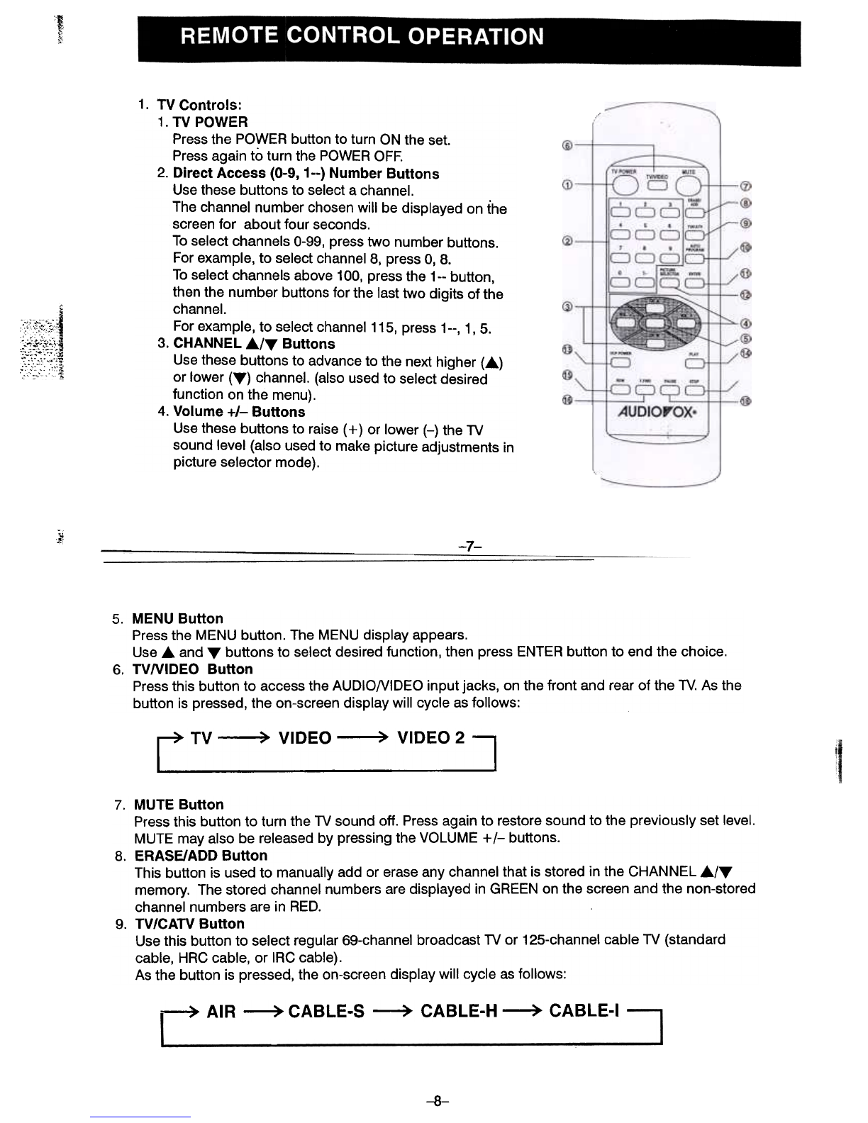
1. TV Controls:
1. TV POWER
Press the POWER button to turn ON the set.
Press again to turn the POWER OFF.
2. Direct Access (0-9, 1--) Number Buttons
Use these buttons to select a channel.
The channel number chosen will be displayed on the
screen for about four seconds.
To select channels 0-99, press two number buttons.
For example, to select channel 8, press 0, 8.
To select channels above 100, press the 1-- button,
then the number buttons for the last two digits of the
channel.
For example, to select channel 115, press 1--, l' 5.
3. CHANNEL .../""' Buttons
Use these buttons to advance to the next higher (...)
or lower (""') channel. (also used to select desired
function on the menu).
4. Volume +1- Buttons
Use these buttons to raise (+ ) or lower (-) the TV
sound level (also used to make picture adjustments in
picture selector mode).
;"
~! -7-
5. MENU Button
Press the MENU button. The MENU display appears.
Use and T buttons to select desired function, then press ENTER button to end the choice.
6. TVNIDEO Button
Press this button to access the AUDIONIDEO input jacks, on the front and rear of the TV. As the
button is pressed, the on-screen display will cycle as follows:
rTV~VIDEO~VID2
7. MUTE Button
Press this button to turn the TV sound off. Press again to restore sound to the previously set level.
MUTE may also be released by pressing the VOLUME +1- buttons.
8. ERASE/ADD Button
This button is used to manually add or erase any channel that is stored in the CHANNEL .1"",
memory. The stored channel numbers are displayed in GREEN on the screen and the non-stored
channel numbers are in RED.
9. TV/CATV Button
Use this button to select regular 69-channel broadcast TV or 125-channel cable TV (standard
cable, HRC cable, or IRC cable).
As the button is pressed, the on-screen display will cycle as follows:
~ AIR ~ CABLE-S ~ CABLE-H ~ CABLE-I
-8-