Aurora Deck Lighting ODYSSEY User manual
Revised October 2020
Aurora Deck Lighting
ODYSSEY LED STRIP LIGHTING KIT
YOUR COMPLETE KIT INCLUDES:
a. 4 LED Strip Lights
b. 12 Connectors
c. 100’ of Twisted Wire
d. LED Power Dri er with Power Cord
(Capacity up to 24 Lineal Foot of LED Lighting)
e. Remote Dri er
f. Remote Control
REQUIREMENTS:
Before you begin, make sure you have an external, weatherproof,
protected 110 volt outlet that meets GFC (ground fault circuit
interrupter) standards. Mount the LED Driver at least 18 inches above the
ground. Best results can be achieved when you have access to the
underside of your deck or installation surface. Do not install more than
23 Lineal Feet of Odyssey LED Strip Lighting on one 3 Amp (36 Watt)
driver box. Do not install more than 16 Lineal Feet of Odyssey Strip
Lighting per run.
Use on steps, railings,
handrails, coves, sots,
gazebos & pergolas,
kitchen cabinets, or
anywhere you need small
bright lighting for years
of service.
TOOLS:
Power Drill • Table Saw or Router • 3/16” Ker table saw blade or 3/16” straight router bit • ½” spade bit or orstner bit •
Screwdriver • Pliers • Tape Measure • Clear silicone caulk or sealant • Eye protection
I n t a l l a t i o n I n t r u c t i o n
CAUTION: Use eye protection when using power tools. Do not install more than 24 lineal feet of LED Strip Lights on one 3 AMP dri er box.
Do not install within 10 feet of a pool, fountain or spa.
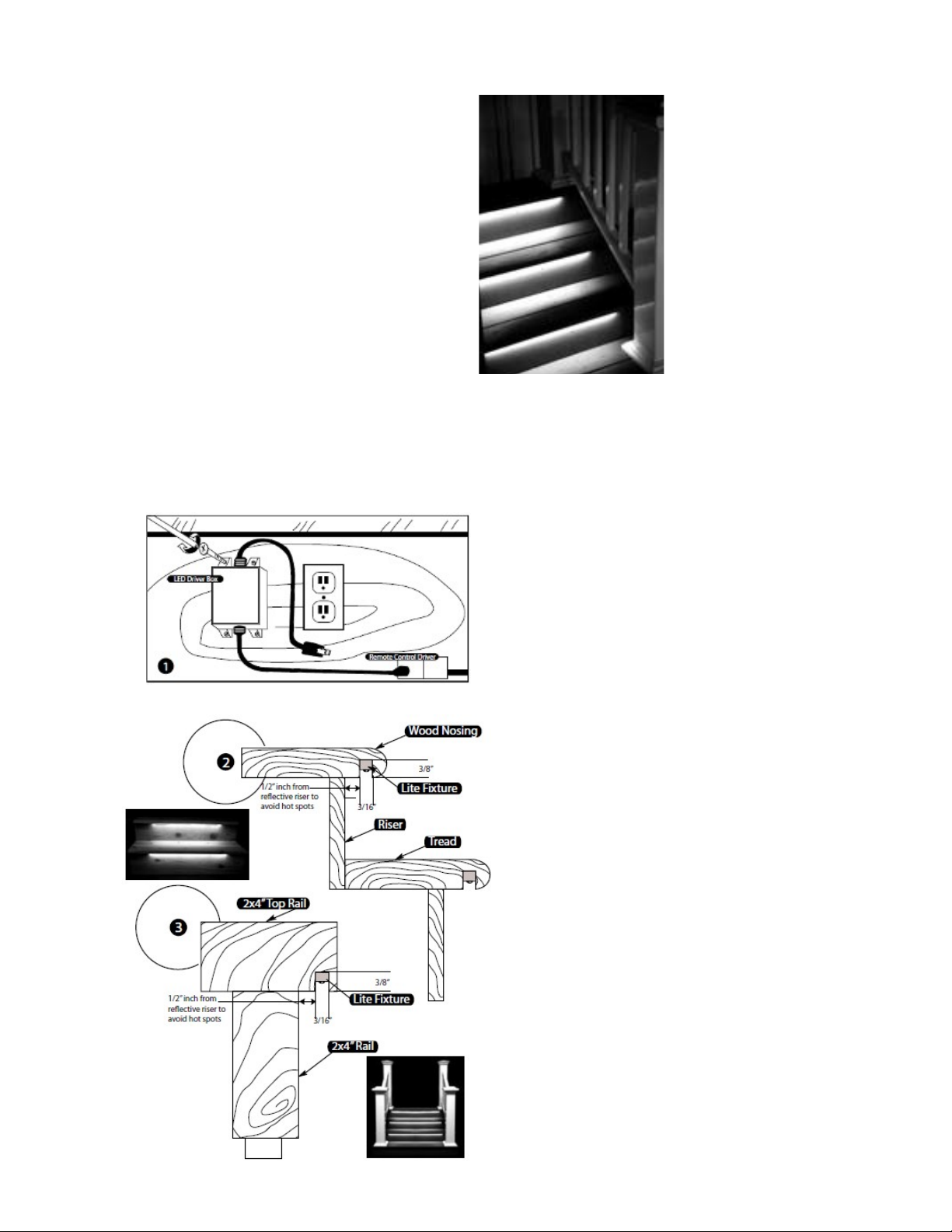
POWER SOURCE: Mount the LED Driver Box
at least 18 inches abo e the ground near your outlet
using screws. Do not plug it in. [ILLUS. 1]
Determine the locations for your LED lights on your
railing, stair nosing, etc. Keep in mind that your
arthest LED Strip light can be no more than 100
feet from the LED dri er box using the wire
included in this kit.
FOR STAIR INSTALLATION: [ILLUS. 2]
using a table saw or router, cut a 3/16” wide x
3/8” deep channel the ull length of the stair
nosing. For best results, The LED Strip should be
at least ½” rom stair riser to a oid hot spots.
FOR HANDRAIL INSTALLATION: [ILLUS.
3] using a table saw or router, cut a 3/16”
wide x 3/8” deep channel the ull length of the
handrail. For best results, The LED Strip should
be at least ½” rom
horizontal surfaces to a oid hot spots. The bottom of
your hole needs to be flat so the light lays in
correctly.
Prior to gluing the LED Strip lighting into place, be
sure to lay out your LED Strips in such a way that
you can connect the wires from one LED strip to the
next. If your LED strips will be more than 8’ apart,
you can use portions of the 100’ wire included in
the kit to extend the LED strip. If your wires will
be less than 8’ apart, you can trim the length of wire
to required length. Please note the location that the
wire connectors will end up before you trim the wires
– you will need a pocket or void to conceal the
wire connectors.
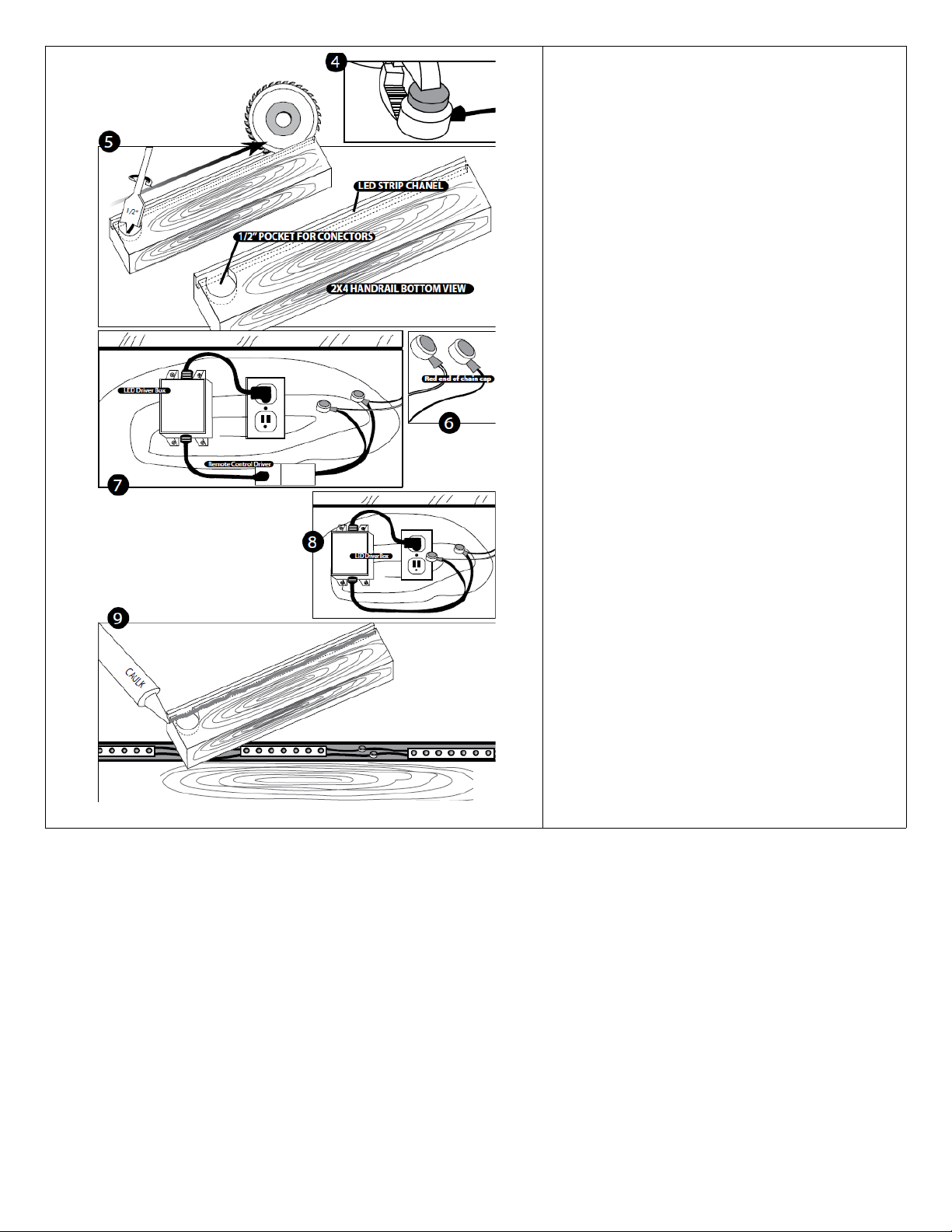
Starting with the LED Strip farthest from the power
source, connect the LED Strips in series. There is no
need to cut or strip the wire. First insert the black wires
into the open side of a connector so that it fits snugly in
the space pro ided. Squeeze the connector closed using
a pair of pliers. Repeat this process to connect the white
wires with another connector. Connect all lights in this
manner. [ILLUS. 4]
At each connection point, you will need a pocket or a
oid to conceal the connectors. This can be done using a
1/2:” spade or forstner bit. Drill a ½” deep hole to allow
space for the connectors. [ILLUS. 5]
NOTE: The LED Strips farthest from the power source
(The last LED Strip on the wire run) will be capped
separately with a connector at the end of your
installation. Do not connect the white and black wires on
the same connector – this will short the entire system. It
is ok to cut the remaining 4’ of wire if needed to conceal
the connectors. See Figure #6
Once all of the LED Deck lights ha e been connected to
the wire, connect the end of the twisted wire to the
remote dri er or power box. Connect the Remote Control
Dri er wires to the end of the twisted wire using two
connectors. The black wire must be connected to the
positi e wire lead as noted on the transformer, and the
white wire must be connected to the negati e wire. See
Figure #7
Use of the remote is optional and the remote dri er can
be bypassed by remo ing it from the power source. See
Figure #8
Plug in the power source to make sure all lights are
working properly. Unplug before proceeding to the final
steps.
Using a caulk gun, run a bead of silicone sealant or caulk
in the channel the entire distance of the slot cut for the
LED Strip and wire. [ILLUS. 9] Do not use excessi e
amounts of silicone. Center the LED Strip on the
material, and press into the slot so that it seats down
e enly in the slot. If needed, a bead of silicone can
o erlay the wires to pro ide additional hold.
When all lights are installed, plug in the power cord, and
operate using either the remote control or the light
switch.
T R O U B L E SHOOT I N G T I P S :
Make sure all wires are connected in like color pairs. Make sure the remote control has a battery and it is installed correctly. If you choose
to bypass the remote, be sure to remo e the remote dri er from the set-up and connect the twisted pair wires directly to the power box.
WA R R A N T Y I N F O R MAT I O N
The Odyssey Strip Lighting Kit is covered by a one year limited warranty.
This product is warranted against defects in materials or workmanship as follows:
Units will be repaired or replaced, at our option, without charge for parts or labor for one year from date of purchase. Repairs and parts
fees are the responsibility of the product owner after the indicated period of one year. The limited warranty cannot be transferred and is
alid only for the purchaser of the product. It does not co er damage or failure caused by or attributable to natural disaster, abuse,
misuse, improper or abnormal use, faulty installation, improper maintenance, lightning, or other incidences of excessi e oltage, or any
repairs or tampering by other than our Warranty Ser ices Department. Products pro en defecti e in workmanship or material are
co ered solely by the remedies of repair or replacement as pro ided by the terms of this warranty. Under no circumstances shall Aurora
Deck Lighting be liable for any loss or damage, direct, or incidental, arising out of the use of or inability to use this product. Some states
do not allow limitations on how long an implied warranty lasts or the exclusions or limitations of incidental or consequential damages,
so the abo e limitations may not apply to product owners in certain states. To obtain warranty ser ice, call 800 603 3520 for a return
merchandise authorization number, and send the product with a copy of the sales receipt and a description of the problem, along with
your name, address, and phone number to:
Aurora Deck Lighting, 960 E Milwaukee St. Whitewater, WI 53190
Repairs will be returned to the customer using UPS Ground ser ice. Other carriers may be used at our option. If faster deli ery is requested, the product
owner must pay the cost dierence o er the UPS Ground ser ice charge. Aurora Deck Lighting is not liable for products lost or damaged during shipment.
Popular Home Lighting manuals by other brands


JONATHAN Y
JONATHAN Y JYL6007A quick start guide

Philips
Philips Ledino 31606/11/16 Specifications

Safavieh Lighting
Safavieh Lighting CANDRI TBL4427A manual

Hunter
Hunter Bullet Spotlight Kit Owner's guide and installation manual

Philips
Philips 405441213 user manual

Philips
Philips Halogen Light Brochure & specs


