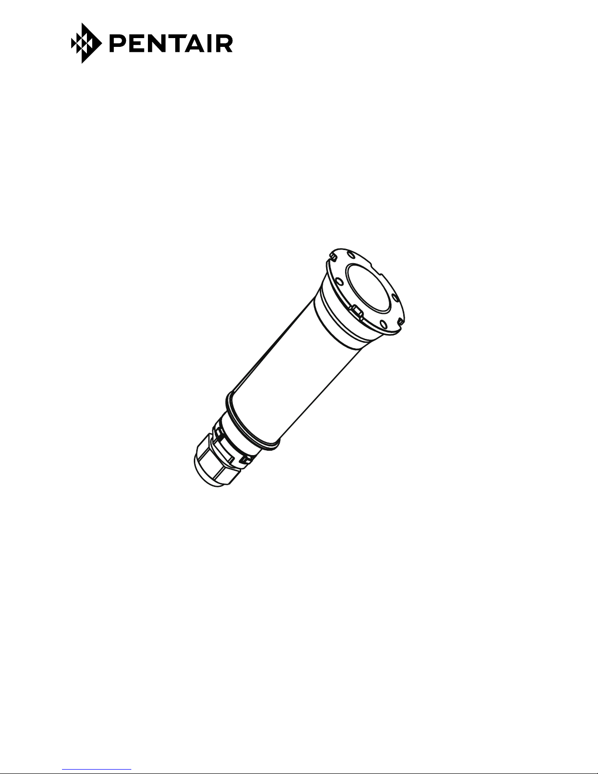
GLOBRITE™ White LED Light Installation and User’s Guide GLOBRITE™ White LED Light Installation and User’s Guide
iii
Most states and local codes regulate the construction, installation, and
operationofpublicpoolsandspas,andtheconstructionofresidentialpoolsand
spas. Itis importanttocomplywiththesecodes,manyofwhich directlyregulatetheinstallation
and use of this product. Consult your local building and health codes for more information.
SERIOUS BODILY INJURY OR DEATH CAN RESULT IFTHIS LIGHT
IS NOT INSTALLED AND USED CORRECTLY.
Before installing this product, read and follow all warning notices
and instructions in this Guide. Failure to follow warnings and
instructions can result in severe injury, death, or property damage.
Call (800) 831-7133 for additional free copies of these instructions.Please refer to www.
pentairpool.com for more information related to this products.
IMPORTANT NOTICE - Attention Installer: This Installation and User’s
Guide(“Guide”)containsimportantinformationabouttheinstallation,operation
andsafeuseof thisunderwaterpool andspalight.This Guideshould begiven
to the owner and/or operator of this equipment.
Before working or servicing pool lights, always disconnect
power to the pool and/or spa lights at the source circuit
breaker. Failure to do so could result in death or serious injury
to service person, pool users or others due to electric shock.
When installing and using this electrical equipment, basic
safety precautions should always be followed.
RISK OF ELECTRICAL SHOCK OR ELECTROCUTION:
This underwater light must be installed by a licensed or certified electrician or a
qualified pool professional in accordance with the current National Electrical Code
(NEC), NFPA 70 or the Canadian Electrical Code (CEC), CSA C22.1. All applicable
local installation codes and ordinances must also be adhered to. Improper installation
will create an electrical hazard which could result in death or serious injury to pool
users, installers or others due to electrical shock, and may also cause damage to
power source. Always disconnect the power to the pool light at the circuit breaker
before servicing the light. Failure to do so could result in death or serious injury to
service person, pool users or others due to electrical shock.
UNDERWATER POOL LIGHTS REQUIRE HIGH VOLTAGE WHICH
CAN SHOCK, BURN, OR CAUSE DEATH.
Forcountries incompliancewith InternationalElectrotechnical
Commission (IEC) regulatory standards: The light fixture must
be installed by a licensed or certified electrician or a qualified pool service person, in
accordance with current IEC 364-7-702 and all applicable local codes and ordinance.
Improper installation will create an electrical hazard, which could result in death or serious
injury to pool user, installer or other due to electrical shock and may also cause damage
to the property.
INSTALLERS, POOL OPERATORS AND POOL OWNERS MUST
READTHESE WARNINGS AND ALL INSTRUCTIONS BEFORE
USINGTHE POOL AND/OR SPA LIGHT.
IMPORTANT WARNING AND SAFETY INSTRUCTIONS