Austria Email WPA 233 ECO User manual

EN
Operating and Installation Instructions
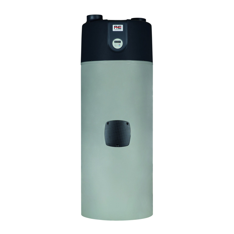
Heat pump with air duct for heating hot water
WPA 233 ECO
WPA 303 ECO
Please forward this on to the user!

© Austria Email AG
1 id.: 1 -14-35-1251-08 | 02.2016
Installation and Operating Instructions - Version 08 - as of 06.2016
Printed in Austria, Copyright by Austria Email AG
Protected by copyright. Any use outside of the boundaries of the copyright without the consent of Austria
Email AG is prohibited and punishable. All previous versions are hereby rendered invalid. The right to
changes is reserved.

© Austria Email AG
id.: 1 -14-35-1251-08 | 02.2016 2
1. Table of Contents
1.
Table of Contents 2
2.
Introduction 3
2.1
Symbols 3
2.2
General 4
2.2.1
Responsibility of the manufacturer 4
2.2.2
Customer Services 4
2.2.3
Responsibility of the installer 4
2.2.4
Responsibility of the user 5
2.3
Compliance 5
2.3.1
Directives 5
2.3.2
Standards 5
2.3.3
Testing 5
3.
Safety instructions and recommendations 5
3.1
Safety instructions 5
3.2
Recommendations 6
3.3
Safety data sheet: R-134a refrigerant 6
3.3.1
Identification 6
3.3.2
Hazard symbols 6
3.3.3
Composition
3.3.4
First Aid
3.3.5
Fire safety measures
3.3.6
In the event of a leak
3.3.
Handling
3.3.8
Protection of persons 8
3.3.9
Recycling 8
3.3.10
Directives 8
4.
Technical Description 9
4.1
General 9
4.2
Structure 10
4.3
Functional Description 11
4.4
Technical Data 13
5.
Assembly 13
5.1
Product contents 13
5.2
Storage 13
5.3
Transport 13
5.4
Installation location of the HP 14
5.5
Installation 16
5.5.1
Hydraulic connections 16
5.5.2
Air duct connection 1
5.5.3
Condensate drain connector 18
5.5.4
Installation of the additional heating source 20
5.5.5
Electrical Connection 21
6.
Putting into operation 23
6.1
Filling the system with water 23
6.2
Checks before starting 24
6.3
Connection of the HP to the voltage power grid 24
6.4
Operation 24
6.5
Settings 24
.
Uninstalling and disposal 2
8.
Servicing 2
8.1
General 2
8.2
Care and maintenance 28
8.2.1
Care 28
8.2.2
Servicing 28
9.
Troubleshooting 28
9.1
Warning sign 28
9.2
Error indication 29
10.
Guarantee, Warranty and Product Liability 30

3
2. Introduction
We would like to thank you for the confidence you have shown in us by purchasing our heat pump. We are
certa
in that the device will serve you well and we enjoy a mutual satisfaction. Before using for the first time,
please read these operating instructions carefully. The operating instructions are compiled in such a way that
you have all the information you need
explain the function of the device to you and demonstrate its operation. Of course, our company is also glad
to be at your disposal through the Customer Services and Sales Departm
require. Keep these instructions in a safe place and, if applicable, please pass them on to subsequent
owners.
2.1 Symbols
During the assembly, maintenance and application of the heat pump, there is the possibility of different
dang
er levels. Certain sections of this guide contain R
with potential hazards as well as ensure the safety of the user and the correct functioning of the equipment.
It is imperative that these sections are take
D NGER
Risk of the occurrence of certain situations that can cause serious injury.
W RNING
Risk of the occurrence of certain situations that could cause light injuries.
C UTION
Risk of damage to the equipment.
C UTION
It
is imperative that the user and installation manuals are read carefully.
D NGER
Electrical hazard
REM RK
Important information
id.: 1
We would like to thank you for the confidence you have shown in us by purchasing our heat pump. We are
in that the device will serve you well and we enjoy a mutual satisfaction. Before using for the first time,
please read these operating instructions carefully. The operating instructions are compiled in such a way that
you have all the information you need
to use the heat pump. It is still important to have your licensed installer
explain the function of the device to you and demonstrate its operation. Of course, our company is also glad
to be at your disposal through the Customer Services and Sales Departm
ents for any advice you may
require. Keep these instructions in a safe place and, if applicable, please pass them on to subsequent
During the assembly, maintenance and application of the heat pump, there is the possibility of different
er levels. Certain sections of this guide contain R
-
sets, by means of which we would like to do away
with potential hazards as well as ensure the safety of the user and the correct functioning of the equipment.
It is imperative that these sections are take
n note of!
Risk of the occurrence of certain situations that can cause serious injury.
Risk of the occurrence of certain situations that could cause light injuries.
Risk of damage to the equipment.
is imperative that the user and installation manuals are read carefully.
Electrical hazard
Important information
© Austria Email AG
id.: 1
-14-35-1251-08 | 02.2016
We would like to thank you for the confidence you have shown in us by purchasing our heat pump. We are
in that the device will serve you well and we enjoy a mutual satisfaction. Before using for the first time,
please read these operating instructions carefully. The operating instructions are compiled in such a way that
to use the heat pump. It is still important to have your licensed installer
explain the function of the device to you and demonstrate its operation. Of course, our company is also glad
ents for any advice you may
require. Keep these instructions in a safe place and, if applicable, please pass them on to subsequent
During the assembly, maintenance and application of the heat pump, there is the possibility of different
sets, by means of which we would like to do away
with potential hazards as well as ensure the safety of the user and the correct functioning of the equipment.
Risk of the occurrence of certain situations that can cause serious injury.
Risk of the occurrence of certain situations that could cause light injuries.
is imperative that the user and installation manuals are read carefully.

© Austria Email AG
id.: 1 -14-35-1251-08 | 02.2016
2.2 General
2.2.1
Responsibility of the manufacturer
Our products are in compliance with the current EU
the CE marking and include all the necessary documents.
In the interest of the users, improvements to the quality and safety of the equipment are co
made. All the specifications outlined in this document can thus be changed without notice.
As a manufacturer we cannot take responsibility in scenarios such as the following:
- Non-
compliance with the operating instructions.
- Incorrect and/or
inadequate maintenance of the equipment.
- Non-
compliance with the installation instructions.
2.2.2 Customer Services
Servicing and the remedy of defects during the guarantee period are carried out by Austria Email AG.
When ordering spare parts for this device,
• the product
• exact type designation of the product
• serial number
• build year
All the information needed to order spare parts can be found on a sign or sticker on the device.
NOTE
The manufacturer 's warranty becomes void in the event of modifications to the device,
replacement of original parts or forcible or improper use of the device. Any costs resulting from
technical interventions shall be borne by the user.
During the warrant
y period, the repair and maintenance work may only be carried out by the
manufacturer or by an authorised service technician. In the event of an error, the warranty
expires.
2.2.3
Responsibility of the installer
The installer is responsible for ensuring that t
with the following conditions:
-
The operating and assembly instructions included with the equipment must be read thoroughly.
-
The installation of the equipment must be carried out in accordance w
legislation, regulations and standards.
-
The installer must carry out the first putting into operation and eliminate all possible mistakes that
come into being during the putting into operation.
-
The operation of the entire syst
-
It must be made clear to the user that the system must be maintained on a regular basis so that
appropriate operation of the equipment throughout its life cycle can be guaranteed.
Responsibility of the manufacturer
Our products are in compliance with the current EU
-
directives and standards. The products are marked with
the CE marking and include all the necessary documents.
In the interest of the users, improvements to the quality and safety of the equipment are co
made. All the specifications outlined in this document can thus be changed without notice.
As a manufacturer we cannot take responsibility in scenarios such as the following:
compliance with the operating instructions.
inadequate maintenance of the equipment.
compliance with the installation instructions.
Servicing and the remedy of defects during the guarantee period are carried out by Austria Email AG.
When ordering spare parts for this device,
please provide the following information:
• exact type designation of the product
All the information needed to order spare parts can be found on a sign or sticker on the device.
The manufacturer 's warranty becomes void in the event of modifications to the device,
replacement of original parts or forcible or improper use of the device. Any costs resulting from
technical interventions shall be borne by the user.
y period, the repair and maintenance work may only be carried out by the
manufacturer or by an authorised service technician. In the event of an error, the warranty
Responsibility of the installer
The installer is responsible for ensuring that t
he equipment is installed and put into operation in accordance
The operating and assembly instructions included with the equipment must be read thoroughly.
The installation of the equipment must be carried out in accordance w
ith the applicable national
legislation, regulations and standards.
The installer must carry out the first putting into operation and eliminate all possible mistakes that
come into being during the putting into operation.
The operation of the entire syst
em must be explained to the user.
It must be made clear to the user that the system must be maintained on a regular basis so that
appropriate operation of the equipment throughout its life cycle can be guaranteed.
4
directives and standards. The products are marked with
In the interest of the users, improvements to the quality and safety of the equipment are co
nstantly being
made. All the specifications outlined in this document can thus be changed without notice.
Servicing and the remedy of defects during the guarantee period are carried out by Austria Email AG.
All the information needed to order spare parts can be found on a sign or sticker on the device.
The manufacturer 's warranty becomes void in the event of modifications to the device,
replacement of original parts or forcible or improper use of the device. Any costs resulting from
y period, the repair and maintenance work may only be carried out by the
manufacturer or by an authorised service technician. In the event of an error, the warranty
he equipment is installed and put into operation in accordance
The operating and assembly instructions included with the equipment must be read thoroughly.
ith the applicable national
The installer must carry out the first putting into operation and eliminate all possible mistakes that
It must be made clear to the user that the system must be maintained on a regular basis so that
appropriate operation of the equipment throughout its life cycle can be guaranteed.

© Austria Email AG
5 id.: 1 -14-35-1251-08 | 02.2016
- All maintenance work must be indicated in the maintenance notes at the end of this manual.
- All of the documents included with the equipment must be given to the user.
2.2.4 Responsibility of the user
To ensure uninterrupted and effective functioning of the system, the user must take the following instructions
into account:
- The operating and assembly instructions included with the equipment must be read thoroughly.
- The installation and the first putting into operation must be carried out by a qualified and authorised
person.
- The user must demand a detailed explanation of the operation of the entire system from the
authorised installer.
- The user must guarantee regular inspection and maintenance of the system by a designated service
representative.
- This operating instruction document must be kept in a suitable and dry location near the equipment.
2.3 Compliance
The CE marking indicates that the device meets the essential requirements of the relevant directives.
2.3.1 Directives
- DIRECTIVE 2006/95/EC OF THE EUROPEAN PARLIAMENT AND OF THE
COUNCIL from 12 December, 2006 for the approximation of the laws of the
Member States relating to electrical equipment designed for use within certain
voltage limits
- DIRECTIVE 2004/108/EC OF THE EUROPEAN PARLIAMENT AND OF THE
COUNCIL from 15 December, 2004 for the approximation of the laws of the
Member States relating to electromagnetic tolerance and for the removal of the
directive 89/336/EWG
2.3.2 Standards
- SIST EN 60335-1:2012
- SIST EN 60335-2-40:2003+A1:2006+A2:2009+A11:2004+A12:2005
- SIST EN 61000-3-2:2006
- SIST EN 61000-3-3:1995:A1:2001+A2:2005
- SIST EN 55014-1:2000+A1:2001+A2:2002
- SIST EN 55014-2:199 +A1:2001
- SIST EN 3 8-2:2008
2.3.3 Testing
To ensure a high quality standard, each heat pump is tested for the following before delivery:
- Tightness of the refrigeration system
- Water tightness
- Airtightness
- Electrical safety
- Functionality
3. Safety instructions and recommendations
3.1 Safety instructions
The device was manufactured in accordance with technical standards that allow the manufacturer to affix the
CE marking to the device. As a warning against possible dangers involved with the operation of the heat
pump, information signs and symbols (pictograms) are attached to the device. The following diagram
illustrates the meaning of the information signs (pictograms).
In addition to symbols (pictograms) and information signs, a sign or sticker with the device's technical data is
also attached to the device.

© Austria Email AG
id.: 1 -14-35-1251-08 | 02.2016
3.2 Recommendations
The device must only be operated by experts and trained personnel who can guarantee safe operation and
maintenance using these operating instructions. During operation, it is forbidden to move or relocate the
device, or to clean or repair it. Before installation and before any subsequent invasive operation inside the
device, it is absolutely imperative to
and maintenance.
The electric installation of the device must be carried out by an authorised person (licensed electrician) while
the device is isolated from the power supply. Disasse
heat pump is forbidden. There must be sufficient space around the heat pump to allow rapid and easy
access in the event of a repair or maintenance. If the water temperature in boiler exceeds 5°C while th
heat pump is operating, Customer Services must be informed immediately. The device must be
disconnected from the network before any work on the heat pump. The heat pump must be set up in such a
way that the mains plug is easily accessible at all times. T
slip floor. At least a 2 my large area must be provided for maintenance. During installation, operation and
maintenance, adequate lighting, with a minimum of 150 Lux, must be provided. It must be ensured tha
device does not endanger anyone, and that children and untrained people are not allowed access during
operation.
3.3 Safety data sheet: R-
134a refrigerant
3.3.1 Identification
Product: R - 134a (HFC - 134a)
The refrigerant belongs to the group of the fluorocar
systems as well as heat pumps.
3.3.2 Hazard symbols
D NGER
Risk of the occurrence of certain situations that can cause serious injury.
1. Risk of health hazards:
-
Refrigerant vapours are heavier than air and can thus displace air from the room. As a result, due to
the lack of air, dizziness, loss of consciousness or even suffocation can ensue.
-
Liquid gas: Contact with the liquid can cause chilblains and serious ey
2.
Product classification: This refrigerant is not referred to as a "harmful product" according to the EU
Directive.
The device must only be operated by experts and trained personnel who can guarantee safe operation and
maintenance using these operating instructions. During operation, it is forbidden to move or relocate the
device, or to clean or repair it. Before installation and before any subsequent invasive operation inside the
device, it is absolutely imperative to
read the contents of the operating instructions to ensure safe operation
The electric installation of the device must be carried out by an authorised person (licensed electrician) while
the device is isolated from the power supply. Disasse
mbly the device and leaning any objects against the
heat pump is forbidden. There must be sufficient space around the heat pump to allow rapid and easy
access in the event of a repair or maintenance. If the water temperature in boiler exceeds 5°C while th
heat pump is operating, Customer Services must be informed immediately. The device must be
disconnected from the network before any work on the heat pump. The heat pump must be set up in such a
way that the mains plug is easily accessible at all times. T
he device must be set up on a hard, flat and non
slip floor. At least a 2 my large area must be provided for maintenance. During installation, operation and
maintenance, adequate lighting, with a minimum of 150 Lux, must be provided. It must be ensured tha
device does not endanger anyone, and that children and untrained people are not allowed access during
134a refrigerant
The refrigerant belongs to the group of the fluorocar
bons that are used in refrigeration and air
Risk of the occurrence of certain situations that can cause serious injury.
Refrigerant vapours are heavier than air and can thus displace air from the room. As a result, due to
the lack of air, dizziness, loss of consciousness or even suffocation can ensue.
Liquid gas: Contact with the liquid can cause chilblains and serious ey
e damage.
Product classification: This refrigerant is not referred to as a "harmful product" according to the EU
6
The device must only be operated by experts and trained personnel who can guarantee safe operation and
maintenance using these operating instructions. During operation, it is forbidden to move or relocate the
device, or to clean or repair it. Before installation and before any subsequent invasive operation inside the
read the contents of the operating instructions to ensure safe operation
The electric installation of the device must be carried out by an authorised person (licensed electrician) while
mbly the device and leaning any objects against the
heat pump is forbidden. There must be sufficient space around the heat pump to allow rapid and easy
access in the event of a repair or maintenance. If the water temperature in boiler exceeds 5°C while th
e
heat pump is operating, Customer Services must be informed immediately. The device must be
disconnected from the network before any work on the heat pump. The heat pump must be set up in such a
he device must be set up on a hard, flat and non
-
slip floor. At least a 2 my large area must be provided for maintenance. During installation, operation and
maintenance, adequate lighting, with a minimum of 150 Lux, must be provided. It must be ensured tha
t the
device does not endanger anyone, and that children and untrained people are not allowed access during
bons that are used in refrigeration and air
-conditioning
Risk of the occurrence of certain situations that can cause serious injury.
Refrigerant vapours are heavier than air and can thus displace air from the room. As a result, due to
the lack of air, dizziness, loss of consciousness or even suffocation can ensue.
e damage.
Product classification: This refrigerant is not referred to as a "harmful product" according to the EU

© Austria Email AG
id.: 1 -14-35-1251-08 | 02.2016
3.3.3 Composition
1. Chemical composition: C
2
H
2
F
4
– Tetrafluoroethane R – 134a
Name of the ingredient Concentration CAS Number CE Number GWP
1, 1, 1, 2 - Tetrafluoroethane R-134a 100% 811-9 -2 212-3 -0 1300
3.3.4 First Aid
REM RK
Important information
1. In the event of inhalation: the person must be removed from the contaminated area and into the
open air. If the person is not feeling well, he/she must be taken to the doctor.
2. In the event of skin contact: Chilblains as well as burns are treated. Rinse thoroughly with clean
water and do not remove the clothing (danger of clothing sticking to skin). In the case of burns,
consult a doctor immediately.
In the event of eye contact: rinse immediately with water and keep the eyelids open (at least 15
minutes). Consult an ophthalmologist.
3.3.5 Fire safety measures
1. Appropriate fire extinguishing substances: any fire extinguishing substances can be used.
2. Unsuitable fire extinguishing substances: not advisable. In the event of a fire, use an appropriate
extinguishing substance.
3. Special hazards:
- Pressure increase. When exposed to air (oxygen), at certain temperatures and pressure conditions,
the formation of flammable substances can occur.
- At high temperatures, toxic and corrosive gases could be released.
4. Special intervention methods: use a fire extinguisher to cool the part of the device or the refrigerant
that is exposed to the heat.
5. Protection of fire fighters:
- Suitable respirators with oxygen pipe.
- Protection of the entire body.
3.3.6 In the event of a leak
1. Special security measures:
- Contact with the skin or eyes should be avoided.
- Intervention without appropriate protective equipment is not recommended.
- Do not inhale the vapours.
- Evacuate the danger zone.
- Plug the leak.
- Remove all potential ignition sources.
- Ventilate the room, in which the refrigerant leaked out (danger of suffocation), well.
2. Cleaning/decontamination: wait until the refrigerant has evaporated.
3.3. Handling
1. Technical measures: In the event of a leak, ventilation is necessary.
2. Precautions:
- Smoking is prohibited.
- Prevent the accumulation of electrostatic charge.
- Maintenance work should only be carried out in well-ventilated rooms.

© Austria Email AG
id.: 1 -14-35-1251-08 | 02.2016
3.3.8 Protection of persons
1.
Protection of the respiratory organs:
-
In the event of insufficient ventilation: the type AX protecti
-
Indoor use: full face mask with the oxygen pipe.
2.
Hand protection: Protective gloves made of nitrite rubber or leather.
3.
Eye protection: safety glasses with side protection.
4.
Skin protection: Clothing made of cotton.
5.
Industrial hygiene: it is prohibit
3.3.9 Recycling
1.
Waste products: consult with the manufacturer regarding the waste recovery or processing.
2. Dirty packaging: re-
use or recycling is possible following decontamination in dedicated facilities.
C UTION
Disposal must be carried out in accordance with local and national regulations.
3.3.10 Directives
Refrigerant removal must be carried out in accordance with the directive EG 842/2006 and other local and
national regulations.
Protection of the respiratory organs:
In the event of insufficient ventilation: the type AX protecti
on mask
Indoor use: full face mask with the oxygen pipe.
Hand protection: Protective gloves made of nitrite rubber or leather.
Eye protection: safety glasses with side protection.
Skin protection: Clothing made of cotton.
Industrial hygiene: it is prohibit
ed to drink, eat or smoke at the workplace.
Waste products: consult with the manufacturer regarding the waste recovery or processing.
use or recycling is possible following decontamination in dedicated facilities.
Disposal must be carried out in accordance with local and national regulations.
Refrigerant removal must be carried out in accordance with the directive EG 842/2006 and other local and
8
Waste products: consult with the manufacturer regarding the waste recovery or processing.
use or recycling is possible following decontamination in dedicated facilities.
Disposal must be carried out in accordance with local and national regulations.
Refrigerant removal must be carried out in accordance with the directive EG 842/2006 and other local and

© Austria Email AG
9 id.: 1 -14-35-1251-08 | 02.2016
4. Technical Description
4.1 General
This facility is a thermal pump which is designed for generating hot water in residential properties and other
premises in which the daily hot water requirement does not exceed 00 litres. With the heating of domestic
water, the heat pump simultaneously cools down the area in which it is installed. The intended use of the
heat pump, in addition to saving large amounts of energy when generating hot water, is to cool down a
selected room (e.g. cellar, storage room etc.). Any change to or replacement of the original components, and
any improper or incorrect use of the device, will nullify the manufacturer's liability, guarantee and warranty.
Consequential costs of any damage which is caused must be paid by the user.
Dimensions:
WP 233
ECO
WP 303 ECO
85 mm 85 mm
B
320 mm 320 mm
C
00 mm 00 mm
D
80 mm 80 mm
E
90 mm 901 mm
F
8 5 mm 11 5 mm
G
10 5 mm 13 6 mm
H
1140 mm 1422 mm
I
1550 mm 1848 mm
1
Cold water connection G1‘‘
2
Tube register – return flow
3
Tube register – flow
4
Flange DN120
5
Circulation G3/4‘‘
6
Warm water connection G1‘‘
7
Condensate connection Φ16
8
Flange cap

© Austria Email AG
id.: 1 -14-35-1251-08 | 02.2016
4.2 Structure
Heating water with a heat pump is an environmentally friendly and efficient method of supply water in
buildings. The WPA
303 ECO is a unit comprising a water heater and assembly (compressor, evaporator,
fan, etc.). The hood of the heat pump is made of plastic and has two pipe nozzles for connection to a pipe
system. The heat pump also offers the possibility of ventilating a
compressor, evaporator, centrifugal ventilator, dry filter, copper and electric installation. The heat pump
assembly operates the entire thermodynamic process for the water heater in the storage tank.
Heat pump housing
Ventilator
Evaporator
Compressor
Control
Hot water storage tank
Sensor
duct external
Sensor dip rod
Mg. Anode
El. heating rod
Hot water heat exchanger
Liquefier
Levelling feet
Heating water with a heat pump is an environmentally friendly and efficient method of supply water in
303 ECO is a unit comprising a water heater and assembly (compressor, evaporator,
fan, etc.). The hood of the heat pump is made of plastic and has two pipe nozzles for connection to a pipe
system. The heat pump also offers the possibility of ventilating a
selected room. The assembly comprises:
compressor, evaporator, centrifugal ventilator, dry filter, copper and electric installation. The heat pump
assembly operates the entire thermodynamic process for the water heater in the storage tank.
10
Heat pump housing
Hot water storage tank
duct external
Hot water heat exchanger
Heating water with a heat pump is an environmentally friendly and efficient method of supply water in
303 ECO is a unit comprising a water heater and assembly (compressor, evaporator,
fan, etc.). The hood of the heat pump is made of plastic and has two pipe nozzles for connection to a pipe
selected room. The assembly comprises:
compressor, evaporator, centrifugal ventilator, dry filter, copper and electric installation. The heat pump
assembly operates the entire thermodynamic process for the water heater in the storage tank.

© Austria Email AG
11 id.: 1 -14-35-1251-08 | 02.2016
4.3 Functional Description
1
Compressor
10
Mg. Anode
2
Liquefier
11
El. heating rod - safety thermostat-sensor
3
Filter-drier
12
High pressure switch
4
Expansion valve
13
Sensor - heat pump
5
Evaporator
14
Hot water heat exchanger
6
Ventilator
15
Hot water storage tank
7
Solenoid valve
8
Sensor - expansion valve
9
El. heating rod
The refrigerant circuit in the thermal pump is a closed system in which the cooling agent R134a is circulated
as the energy carrier. When the evaporating temperature is low, heat is extracted from the suctioned air in
the fin coil heat exchanger and transferred to the cooling agent. The vaporous cooling agent is suctioned
from the compressor, compressed to a higher pressure and temperature level and further transported to the
condenser. Here, the heat absorbed in the evaporator and a part of the compressor energy is released into
the water. Using a throttle (expansion valve), the evaporation pressure is reduced and the cooling agent can
continue to absorb heat from the suctioned air.
Water heater (hot water tank)
The water heater is enamelled on the inside, cased on the outside with polyurethane and surrounded with
steel plate. The water heater contains a heat exchanger as standard for connection with the boiler; this is
used when bivalent operation is selected. A protective anode is fitted in the water heater which prevents
corrosion in the event of damage to the enamel. In order that the device can be set up on an uneven surface,
three knuckle feet are enclosed loose which are covered with heat insulation during the foaming process.
Remove this heat insulation before screwing the feet on. Please use a water level to ensure a horizontal
alignment.
dditional electric heating rod
The electric heating rod EH installed with output of 1.5 kW is used for:
• fast water heating; the WP and the heating rod are active simultaneously
• The protection function of the evaporator; heater turns on automatically when the HP is running
during summer operation and the ambient air temperature drops too far
• alternative heating; in the case of failure of the assembly.

© Austria Email AG
id.: 1 -14-35-1251-08 | 02.2016
Frost protection sensor
The thermal pump regulator has an air temperature sensor which measures the temperature of the air which
flows through the evaporator and switches off the TP at an air
In this case, heating is automatically reconnected using an electro heating rod when the HP is in
summertime operation. In wintertime operation, the circulation pump of the connected boiler is switched on.
Safety thermostat of the el
ectric heating rod
The safety thermostat switches off at 85 °C and must then be reset manually.
Monitoring the hot water temperature in the storage tank
The OPTITRONIC regulator is used to monitor the hot water temperature. Depending on the hot water
temperature, this regulator
switches the compressor, the ventilator and, in certain cases, the electric heating
rod or the circulator pump of the boiler on and off. The maximum temperature which can be set is 55°C when
operating with the compressor. In the case of rapid heating using
High pressure control
A high pressure control is fitted in order to protect against excessive pressure in the refrigerant circuit; in the
event of an increase in pressure, the heat pump switches off and thus prev
If the pressure in the system drops, the heat pump is automatically switched on again. In this case "E "
appears on the display.
Operating conditions
In normal operation, the ambient temperature should be between
relative humidity at +40°C should not exceed 50%.
If the ambient temperature is lower, the air humidity can be somewhat higher.
Assembly must not take place at a height of more than 2000 m above sea level. In the case of sys
which are operated at a height above 1000 m, the heat output and air cooling is reduced by the air pressure.
C UTION
The heat pump must on no account be set up in locations in which there may be pollutants or
toxic substances in the air (stables,
The thermal pump regulator has an air temperature sensor which measures the temperature of the air which
flows through the evaporator and switches off the TP at an air
temperature of - °C.
In this case, heating is automatically reconnected using an electro heating rod when the HP is in
summertime operation. In wintertime operation, the circulation pump of the connected boiler is switched on.
ectric heating rod
The safety thermostat switches off at 85 °C and must then be reset manually.
The safety thermostat is located below the flange
cap.
-
Pull the plug out of the wall.
-
Unscrew the M5 screw and remove the
flange cap.
-
Press the red button on
thermostat until you hear a "click".
- Refit the flange cap.
Monitoring the hot water temperature in the storage tank
The OPTITRONIC regulator is used to monitor the hot water temperature. Depending on the hot water
switches the compressor, the ventilator and, in certain cases, the electric heating
rod or the circulator pump of the boiler on and off. The maximum temperature which can be set is 55°C when
operating with the compressor. In the case of rapid heating using
the "HT" button, the temperature is 60°C.
A high pressure control is fitted in order to protect against excessive pressure in the refrigerant circuit; in the
event of an increase in pressure, the heat pump switches off and thus prev
ents damage to the compressor.
If the pressure in the system drops, the heat pump is automatically switched on again. In this case "E "
In normal operation, the ambient temperature should be between
- °C and +3
5°C. The air must be clean; the
relative humidity at +40°C should not exceed 50%.
If the ambient temperature is lower, the air humidity can be somewhat higher.
Assembly must not take place at a height of more than 2000 m above sea level. In the case of sys
which are operated at a height above 1000 m, the heat output and air cooling is reduced by the air pressure.
The heat pump must on no account be set up in locations in which there may be pollutants or
toxic substances in the air (stables,
storage rooms for hazardous substances, outdoors, etc.).
12
The thermal pump regulator has an air temperature sensor which measures the temperature of the air which
In this case, heating is automatically reconnected using an electro heating rod when the HP is in
summertime operation. In wintertime operation, the circulation pump of the connected boiler is switched on.
The safety thermostat is located below the flange
Pull the plug out of the wall.
Unscrew the M5 screw and remove the
Press the red button on
the safety
thermostat until you hear a "click".
The OPTITRONIC regulator is used to monitor the hot water temperature. Depending on the hot water
switches the compressor, the ventilator and, in certain cases, the electric heating
rod or the circulator pump of the boiler on and off. The maximum temperature which can be set is 55°C when
the "HT" button, the temperature is 60°C.
A high pressure control is fitted in order to protect against excessive pressure in the refrigerant circuit; in the
ents damage to the compressor.
If the pressure in the system drops, the heat pump is automatically switched on again. In this case "E "
5°C. The air must be clean; the
Assembly must not take place at a height of more than 2000 m above sea level. In the case of sys
tems
which are operated at a height above 1000 m, the heat output and air cooling is reduced by the air pressure.
The heat pump must on no account be set up in locations in which there may be pollutants or
storage rooms for hazardous substances, outdoors, etc.).

13
4.4 Technical Data
product
Model
Max. heat output:
Electrical power:
Max el. performance:
El. heating rod:
Voltage:
Max. power consumption of circulator pump:
Cooling agent:
Max. water temperature:
Protection class:
mbient temperature:
Tank
protection
Sound power level
El. Protection
Max. pressure in reservoir:
Max. allowed pressure heating water heat
exchanger:
Max. allowed pressure in cooling
Heating water heat exchanger thermal output:
Tank connections:
Circulation:
ir connection bracket
* If there is an additional e. heating rod
Weight:
Volume
COPt (EN16147; 15W55; XL)
Heat exchanger output:
Required air flow rate:
Minimum ceiling height:
*Electric booster heater
5. ssembly
5.1 Product contents
The delivery includes:
1. Heat pump
2.
Operation and installation instructions
3. Levelling feet
5.2 Storage
The device may only be relocated or moved when it is not in operation. Please note the individual device
dimensions. The permissible temperature during transportati
whereby temporary increases (24 hours maximum) up to 55°C are permissible.
5.3 Transport
During transportation, the heat pump is protected with protective foil and cardboard packaging to prevent
damage such as
indentations and scratches. After transportation, the device must stand upright for at least 2
hours so that the distributed oil collects in the compressor again.
C UTION
The heat pump must on no account be laid horizontally.
id.: 1
Heat pump with air duct for heating hot water
WP 233 ECO
1850 W (3350 W)*
440 W (1940 W)*
560 W (60°C) (1 60 W)*
1500 W
230 V a.c.
Max. power consumption of circulator pump:
300 W
R134a (900 g)
60°C -
65°C ( 5°C)*
IPX1
- -
+35°C
Mg Anode
56 dB(A)
16 A, (230 V a.c.)
1.0 MPa (10 bar) at 95°C
Max. allowed pressure heating water heat
1.0 MPa (10 bar) at 110°C
Max. allowed pressure in cooling
circuit:
2.3 MPa (23 bar)
Heating water heat exchanger thermal output:
15 kW
G 1''
G ¾''
Φ 150 mm
* If there is an additional e. heating rod
WP 233 ECO
130 kg
225 L
2.9
15 kW
380 m
3
/h
2000 mm
1.5 kW
Operation and installation instructions
The device may only be relocated or moved when it is not in operation. Please note the individual device
dimensions. The permissible temperature during transportati
on and storage should be between 10 and 45°C
whereby temporary increases (24 hours maximum) up to 55°C are permissible.
During transportation, the heat pump is protected with protective foil and cardboard packaging to prevent
indentations and scratches. After transportation, the device must stand upright for at least 2
hours so that the distributed oil collects in the compressor again.
The heat pump must on no account be laid horizontally.
© Austria Email AG
id.: 1
-14-35-1251-08 | 02.2016
Heat pump with air duct for heating hot water
WP 303 ECO
1850 W (3350 W)*
440 W (1940 W)*
560 W (60°C) (1 60 W)*
230 V a.c.
R134a (900 g)
65°C ( 5°C)*
+35°C
Mg Anode
56 dB(A)
16 A, (230 V a.c.)
1.0 MPa (10 bar) at 95°C
1.0 MPa (10 bar) at 110°C
2.3 MPa (23 bar)
Φ 150 mm
WP 303 ECO
150 kg
300 L
3.0
15 kW
380 m
3
/h
2200 mm
1.5 kW
The device may only be relocated or moved when it is not in operation. Please note the individual device
on and storage should be between 10 and 45°C
During transportation, the heat pump is protected with protective foil and cardboard packaging to prevent
indentations and scratches. After transportation, the device must stand upright for at least 2

© Austria Email AG
id.: 1 -14-35-1251-08 | 02.2016
5.4 Installation location of
the HP
The heat pump must on no account be set up in locations in which there may be pollutants or toxic
substances in the air (stables, storage rooms for hazardous substances, outdoors etc.). The minimum ceiling
height must be 2100 mm. The minimum room si
that it sucks in the air for ventilation through the pipe system from the room or from the surroundings. The
sucked in air emits its heat to the heat pump and is then, depending on requirements, you
needs, fed back into the selected room or into the surroundings. The heat pump enables the following types
of ventilation which depend on the design of the piping system:
Image 1
: Suctioning from the adjoining room
cooling)
Image 2: Suctioning from the room -
blowing out into the same or a room further away
the HP
The heat pump must on no account be set up in locations in which there may be pollutants or toxic
substances in the air (stables, storage rooms for hazardous substances, outdoors etc.). The minimum ceiling
height must be 2100 mm. The minimum room si
ze must be 20 m
3
. The heat pump is designed in such a way
that it sucks in the air for ventilation through the pipe system from the room or from the surroundings. The
sucked in air emits its heat to the heat pump and is then, depending on requirements, you
needs, fed back into the selected room or into the surroundings. The heat pump enables the following types
of ventilation which depend on the design of the piping system:
: Suctioning from the adjoining room
-
blowing out into the same adjoining room (adjoining room
blowing out into the same or a room further away
14
The heat pump must on no account be set up in locations in which there may be pollutants or toxic
substances in the air (stables, storage rooms for hazardous substances, outdoors etc.). The minimum ceiling
. The heat pump is designed in such a way
that it sucks in the air for ventilation through the pipe system from the room or from the surroundings. The
sucked in air emits its heat to the heat pump and is then, depending on requirements, you
r desires and
needs, fed back into the selected room or into the surroundings. The heat pump enables the following types
blowing out into the same adjoining room (adjoining room

15
Image 3
: Suctioning from the adjoining room
Image 4: Suctioning from the room -
blowing out into the surroundings
The most common pipe system implementation is that in which air is sucked in from rooms that are subject
t
o a great deal of heat loss and is then directed to the heat pump, which is usually installed in the cellar.
Some of the heat is extracted from this air and is then blown out back into the surroundings. Air from
bathrooms, kitchens, toilets, etc., frequent
surroundings.
id.: 1
: Suctioning from the adjoining room
- blowi
ng out into the same adjoining room (drying washing)
blowing out into the surroundings
The most common pipe system implementation is that in which air is sucked in from rooms that are subject
o a great deal of heat loss and is then directed to the heat pump, which is usually installed in the cellar.
Some of the heat is extracted from this air and is then blown out back into the surroundings. Air from
bathrooms, kitchens, toilets, etc., frequent
ly contain odours and are therefore blown out into the
© Austria Email AG
id.: 1
-14-35-1251-08 | 02.2016
ng out into the same adjoining room (drying washing)
The most common pipe system implementation is that in which air is sucked in from rooms that are subject
o a great deal of heat loss and is then directed to the heat pump, which is usually installed in the cellar.
Some of the heat is extracted from this air and is then blown out back into the surroundings. Air from
ly contain odours and are therefore blown out into the

© Austria Email AG
id.: 1 -14-35-1251-08 | 02.2016
If the HP uses air from the environment in the room, the space must be at least 30 m
5.5 Installation
5.5.1 Hydraulic connections
The water pipe must be connected in accordance with the
connection of water heaters. How to connect the water pipe is shown in Figure 3. The maximum pressure in
the water pipe must not be more than 6 bar. The smooth pipe heat exchanger must be professionally flushed
thro
ugh before carrying out the initial installation (in addition we recommend the installation of a dirt filter). If
the smooth pipe heat exchanger is not used during the operation of the storage tank (e.g. HP only) then this
must be completely filled with a
glycol mixture to avoid corrosion due to the resulting condensation. After it
has been filled up, the filled smooth pipe heat exchanger must not be closed off at both ends (pressure
expansion due to temperature).
If the HP uses air from the environment in the room, the space must be at least 30 m
The water pipe must be connected in accordance with the
norms and regulations which apply to the
connection of water heaters. How to connect the water pipe is shown in Figure 3. The maximum pressure in
the water pipe must not be more than 6 bar. The smooth pipe heat exchanger must be professionally flushed
ugh before carrying out the initial installation (in addition we recommend the installation of a dirt filter). If
the smooth pipe heat exchanger is not used during the operation of the storage tank (e.g. HP only) then this
glycol mixture to avoid corrosion due to the resulting condensation. After it
has been filled up, the filled smooth pipe heat exchanger must not be closed off at both ends (pressure
16
If the HP uses air from the environment in the room, the space must be at least 30 m
3
.
norms and regulations which apply to the
connection of water heaters. How to connect the water pipe is shown in Figure 3. The maximum pressure in
the water pipe must not be more than 6 bar. The smooth pipe heat exchanger must be professionally flushed
ugh before carrying out the initial installation (in addition we recommend the installation of a dirt filter). If
the smooth pipe heat exchanger is not used during the operation of the storage tank (e.g. HP only) then this
glycol mixture to avoid corrosion due to the resulting condensation. After it
has been filled up, the filled smooth pipe heat exchanger must not be closed off at both ends (pressure

© Austria Email AG
1 id.: 1 -14-35-1251-08 | 02.2016
1. Shut-off valve
2. Pressure reduction valve
3. Back-flow valve
4. Safety valve
5. Expansion vessel
6. Drainage Valve
. Circulation pump
8. Heat pump
Expansion vessel dimensioning:
Safety valve pressure setting [bar]
6 10
Pressure in system [bar]
3.0 3.5 4.0 3.0 3.5 4.0
Storage volume [L]
Expansion vessel
volume [L]
300
15 19 26 9 10 10
5.5.2 Air duct connection
The heat pump with air duct has several advantages over the standard compact version and also over the
design with a separate evaporator:
• The heat pump can be set up in any room which is big enough to accommodate it.
• The thermal pump enables the ventilation of a selected room
• The heat pump enables the drawing off of the ambient air and also enables the supply of fresh air
from the surroundings.
• When selecting the room, take into account the diameter and height of the heat pump. There must
be sufficient space above for the pipe channel connections. The minimum distance to the walls must
be 0.5 m.
The air piping system should be designed in such a way that, on its way, the air does not change the
direction of its flow if possible. The pipe length between the intake connection and the outlet connection
should not exceed 10 m. If the flow direction changes more often, that must be regarded as additional air
resistance and the pipe length should be shortened accordingly. A 90° bend therefore means a pipe channel
shorter by 0.5 m. Closure elements (gates, filters, ventilation valves) in the air ventilation system must be
taken into account in the same way. A drop in pressure in the pipe channel which is too high reduces the air
flow. If the air temperature is below +10°C, this can cause the slow freezing of the evaporator and thus
poorer ventilation, which is something which is difficult to notice.
REM RK
It is necessary to install at least a 90° elbow pipe in order to avoid a mixture of air
between the suctioning air channel and the blowing out air channel.

© Austria Email AG
id.: 1 -14-35-1251-08 | 02.2016
Figure 9 below shows the cover of the heat pump. The cover has two brackets, both 40 mm high, and have
an outside diameter of Ø 150.
The access to the inside areas of the thermal pump is covered with a
protective grid which must not be removed.
C UTION
With air duct lengths of more than 5 m, the fan speed must be clamped to
check the circuit diagram (
Max. allowed air duct length:
Maximum air duct length
Inner diameter 150 mm
Inner diameter 160 mm
Inner diameter 200 mm
For the final length of air ducts, the equivalent length of accessories must also be considered.
Accessories
Curve 90° (Φ 160 mm)
Curve 90° (Φ 200 mm)
Reducing part Φ200xΦ160
Outer grille (Φ 160 mm)
5.5.3
Condensate drain connector
Condensation forms in the thermal pump due to the humidity in the air. Between 1 and 5 litres
per day depending on the season and hot water requirement. This condensation can be used for a steam
iron or watering for example. A discharge tube is fitted to the device to drain off the condensation; this is
located to the right on the back o
f the device. If free drainage of the condensation is not possible in the place
of installation, a receptacle with a content of at least 10 litres must be available.
Warning: if longer air pipes are used, a return valve must be fitted at the bottom of the
ensure proper drainage of the condensation and non
Figure 9 below shows the cover of the heat pump. The cover has two brackets, both 40 mm high, and have
The access to the inside areas of the thermal pump is covered with a
protective grid which must not be removed.
With air duct lengths of more than 5 m, the fan speed must be clamped to
check the circuit diagram (
chapter 5.5.5).
m
10 m
15 m
25 m
For the final length of air ducts, the equivalent length of accessories must also be considered.
equivalent length in m
3
2
1
2
Condensate drain connector
Condensation forms in the thermal pump due to the humidity in the air. Between 1 and 5 litres
per day depending on the season and hot water requirement. This condensation can be used for a steam
iron or watering for example. A discharge tube is fitted to the device to drain off the condensation; this is
f the device. If free drainage of the condensation is not possible in the place
of installation, a receptacle with a content of at least 10 litres must be available.
Warning: if longer air pipes are used, a return valve must be fitted at the bottom of the
ensure proper drainage of the condensation and non
-
dissipation of the discharge odour.
18
Figure 9 below shows the cover of the heat pump. The cover has two brackets, both 40 mm high, and have
The access to the inside areas of the thermal pump is covered with a
With air duct lengths of more than 5 m, the fan speed must be clamped to
n2. Please
10 m
15 m
25 m
For the final length of air ducts, the equivalent length of accessories must also be considered.
Condensation forms in the thermal pump due to the humidity in the air. Between 1 and 5 litres
accumulate
per day depending on the season and hot water requirement. This condensation can be used for a steam
iron or watering for example. A discharge tube is fitted to the device to drain off the condensation; this is
f the device. If free drainage of the condensation is not possible in the place
Warning: if longer air pipes are used, a return valve must be fitted at the bottom of the
discharge pipe to
dissipation of the discharge odour.

19
The condensate pipe must be
connected to the device and fed
into the sewer system or into a
collector.
In case of installation of the
condensate water pipe into the
sewage system, we recommend
that you use a siphon to prevent
unwanted odours.
The condensation water drain
must be designed in such a way
that the condensate water can
always drain off more easily. The
condensation water pipe must
always be inclined downwards. If
this is not possible, the
condensation water must be
channelled into a collector and the
collector must be emptied
regularly.
id.: 1
© Austria Email AG
id.: 1
-14-35-1251-08 | 02.2016
This manual suits for next models
1
Table of contents
Other Austria Email Heat Pump manuals
Popular Heat Pump manuals by other brands

Rheem
Rheem P16 Series installation instructions

Vertiv
Vertiv Liebert CRV CCD25 user manual

Jandy
Jandy JE Installation and operation manual

TEV
TEV marstair MRC+ Series Installation & technical manual

Trane
Trane WCK024B1 Installation operation & maintenance

Viessmann
Viessmann VITOCAL 222-G operating instructions

CIAT
CIAT CONDENCIAT CD series Installation, Operation, Commissioning, Maintenance

Unitary products group
Unitary products group AHT8-UH installation manual

Oilon
Oilon GT 28 Operation manual

ANTEK
ANTEK AIR MAGNA 150 Installation and maintenance instructions

Heat Controller
Heat Controller B-VCH12FC-1 installation manual

Panasonic
Panasonic S-26PK1U6 quick guide