Austria Email WPA 303 E-LF Operation manual

ANG
Instructions for Use and Installation
Domestic Hot Water Heat Pump
WPA 303 E-LF
These instructions must be handed over
to the end user.

© Austria Email AG
1
V1.0 1/2021
Instructions for Use and Installation. - Version 1.0 - 01/2021
Printed in Austria, Copyright by Austria Email AG
This text is protected by copyright. Any use outside limits of the copyright act without the consent of
Austria Email AG is illegal and punishable by law. With this all previous version are invalid. We
reserve the right to change the text.

© Austria Email AG
2
V1.0 1/2021
1Table of Contents
1Table of Contents ....................................................................................................................... 2
2Introduction................................................................................................................................ 4
2.1 Symbols.............................................................................................................................. 4
2.2 General .............................................................................................................................. 5
2.2.1 Obligation of the Manufacturer................................................................................ 5
2.2.2 Customer Support - Service ...................................................................................... 5
2.2.3 Obligation of the Installer ......................................................................................... 5
2.2.4 Obligation of the User............................................................................................... 6
2.3 Conformity......................................................................................................................... 6
2.3.1 Directives .................................................................................................................. 6
2.3.2 Standards .................................................................................................................. 6
2.3.3 Factory Testing.......................................................................................................... 6
3Safety Advice and Recommendations........................................................................................ 7
3.1 Safety Advice ..................................................................................................................... 7
3.2 Recommendations............................................................................................................. 7
3.3 Safety Data Sheet: Refrigerant R134a ............................................................................... 8
3.3.1 Identification............................................................................................................. 8
3.3.2 Potential Dangers...................................................................................................... 8
3.3.3 Composition.............................................................................................................. 8
3.3.4 First Aid ..................................................................................................................... 8
3.3.5 Fire-Fighting Measures ............................................................................................. 8
3.3.6 In Case of Leakage..................................................................................................... 9
3.3.7 Handling.................................................................................................................... 9
3.3.8 Personal Protective Equipment ................................................................................ 9
3.3.9 Recycling/Waste Management................................................................................. 9
3.3.10 Directives ................................................................................................................ 10
4Technical Description ............................................................................................................... 10
4.1 General ............................................................................................................................ 10
4.2 Component Parts............................................................................................................. 12
4.3 Operating Principle.......................................................................................................... 13
4.4 Technical Data ................................................................................................................. 15
5Installation................................................................................................................................ 16
5.1 Scope of Delivery............................................................................................................. 16
5.2 Storage............................................................................................................................. 16
5.3 Transport ......................................................................................................................... 16
5.4 Place of Installation ......................................................................................................... 16

© Austria Email AG
3
V1.0 1/2021
5.5 Installation....................................................................................................................... 18
5.5.1 Hydraulic Connection.............................................................................................. 18
5.5.2 Connection of the Air Duct System......................................................................... 19
5.5.3 Connection of Condensate Discharge..................................................................... 20
5.5.4 Connection of the Secondary Source...................................................................... 22
5.5.5 Electrical Connection .............................................................................................. 24
6Heat Pump Start-up.................................................................................................................. 25
6.1 Filling the System with Water.......................................................................................... 25
6.2 Control prior to Start-up.................................................................................................. 25
6.3 Connection of the Heat Pump to the Power Network .................................................... 25
6.4 Start-up............................................................................................................................ 26
6.5 Heat Pump Operation...................................................................................................... 26
6.6 Settings ............................................................................................................................ 27
7Dismantling and Removal......................................................................................................... 30
8Maintenance ............................................................................................................................ 30
8.1 General ............................................................................................................................ 30
8.2 Care and Maintenance .................................................................................................... 31
8.2.1 Care......................................................................................................................... 31
8.2.2 Maintenance........................................................................................................... 31
9Disturbances in the Functioning............................................................................................... 31
9.1 Warning signs .................................................................................................................. 31
9.2 Error Indication................................................................................................................ 32
10 Warranty, Guarantee and Product Liability......................................................................... 33

© Austria Email AG
4
V1.0 1/2021
2Introduction
First, we would like to thank you for your trust, which you showed by purchasing our product and we
firmly believe that the appliance will serve you well. Prior to initial use, carefully read the contents of
the following instructions for safe usage and maintenance and familiarize yourself with the purpose,
functionality and methods of handling with the appliance. The instructions are composed so as to
assure that you are well acquainted with all the necessary actions prior to the initial as well as each
subsequent use. But still, have your licensed installer explain to you the functioning of the device and
demonstrate its operation. Of course, our company is also glad to be at your disposal through the
Customer Services and Sales Departments for any advice you may require.
If you intend to hand over this product to a third person, make sure that you will also enclose the
instructions for safe use and maintenance.
2.1 Symbols
During installation, maintenance works and usage different levels of danger may occur. Certain
chapters and paragraphs contain warning sentences, which are intended to provide the user’s safety,
eliminate possible dangers and ensure a correct operation of the appliance. Please, pay particular
attention to these chapters.
DANGER
Risk of a situation with possible occurrence of heavy personal injuries.
WARNING
Risk of a situation with possible occurrence of light personal injuries.
WARNING
Risk of device damage.
CAUTION
Instructions for use and installation must be read.
DANGER
Danger electricity.
NOTE
Important information.

© Austria Email AG
5
V1.0 1/2021
2.2 General
2.2.1 Obligation of the Manufacturer
Our products are consistent with all current European directives and standards. They are labelled
with the CE sign and have all the necessary documentation.
For the interests of the customers, improvements on the quality and product safety are constantly
being carried out; therefore all specifications set out in this document may be altered without prior
notice.
As a manufacturer, we cannot assume responsibility in the following cases:
-Disregard of the instructions for use.
-False and/or insufficient maintenance of the appliance.
-Disregard of the installation instructions.
2.2.2 Customer Support - Service
Customer support and service during warranty period is guaranteed by Austria Email AG.
When ordering spare parts for this device, please provide the following:
•product
•exact title of the product
•serial number
•production year
All necessary information can be obtained from the identification label located on the appliance.
NOTE
Any modifications or replacements of parts other than original or any forced or
incorrect use of the appliance shall cease the manufacturer's guarantee. Any
possible costs resulting from a servicing procedure shall be settled solely by the
user.
2.2.3 Obligation of the Installer
The installer is responsible for a correct installation and start-up of the appliance, according to the
following requirements:
-The enclosed instructions for installation and use must be read thoroughly.
-Installation of the appliance must be carried out in compliance with the current national
legislation, regulations and standards.
-Implementation of the start-up and elimination of any irregularities detected at the start-up.

© Austria Email AG
6
V1.0 1/2021
-Explanation of the entire system’s operation.
-The fitter must remind the user to carry out regular maintenance works on the appliance to
ensure its proper functioning throughout the entire life-span.
-All maintenance works must be written down in a service record at the end of this instruction
manual.
-All documentation enclosed to the appliance must be handed over to the end user.
2.2.4 Obligation of the User
In order to ensure undisturbed and efficient operation of the appliance, the user must consider the
following instructions:
-Thoroughly read the enclosed instructions for safe use and installation.
-Installation and start-up of the appliance must be performed by an authorised and
technically qualified person.
-Ask the authorised installer to explain in detail the functioning of the appliance and how it is
managed.
-Ensure that the appliance is regularly inspected and maintained by an authorised and
qualified after-sales service technician.
-Keep these instructions for use and maintenance in a suitable dry place near the appliance.
2.3 Conformity
The CE sign confirms that the appliance is manufactured in compliance with the currently valid
directives and standards.
2.3.1 Directives
-DIRECTIVE 2006/95/EC OF THE EUROPEAN PARLIAMENT AND OF THE COUNCIL
of 12 December 2006 on the harmonisation of the laws of Member States relating to
electrical equipment designed for use within certain voltage limits
-DIRECTIVE 2006/42/EC OF THE EUROPEAN PARLIAMENT AND OF THE COUNCIL
of 17 May 2006 on machinery, and amending Directive 95/16/EC
-DRECTIVE 97/23/EC OF THE EUROPEAN PARLIAMENT AND OF THE COUNCIL of 29
May 1997 on the approximation of the laws of the Member States concerning
pressure
-DIRECTIVE 2004/108/EC OF THE EUROPEAN PARLIAMENT AND OF THE COUNCIL
of 15 December 2004 on the approximation of the laws of the Member States
relating to electromagnetic compatibility and repealing Directive 89/336/EEC
2.3.2 Standards
-EN 60335-1:2012
-EN 60335- 2-21
-EN 60335-2-40
-EN 50417
-EN 60730-1
-EN 61000-3-2:2006
2.3.3 Factory Testing
In order to ensure high quality of each heat pump before it is sold, the following tests are carried out:
-tightness of the refrigeration circuit

© Austria Email AG
7
V1.0 1/2021
-water-tightness
-air-tightness
-electrical safety
-functionality
3Safety Advice and Recommendations
3.1 Safety Advice
The appliance is manufactured in accordance with the current directives and standards, which
enables the manufacturer to label the product with the CE sign. In order to maintain safety and
functionality of the appliance, there are warning signs and symbols –pictograms –on the device to
warn the user of potential dangers.
Explanation of warning signs (pictograms) on the device:
Read the Instructions
for use and
instalation
Danger of electric
shock
The device must not
be layed down. Must
stay in vertical
position during
transport and
operation.
3.2 Recommendations
Persons, especially children, who are not capable of operating the device safely due to their physical,
sensory or mental abilities or their inexperience or lack of knowledge, must not operate this device
without supervision or instruction by the person in charge. Children must be supervised to ensure that
they do not play with the device. During operation the device must not be moved, cleaned or mended.
Before installation and any further work on the device, it is necessary to read the contents of the
instructions for safe use and maintenance.
Electrical connection must be carried out by a qualified person and it is necessary to disconnect all
electrical circuits from the power source prior to opening the device. The connection cable must be
accessible and it must be easy to pull the plug from the socket. It is forbidden to place any kind of
objects around or on top of the device. Free access to the appliance must be provided at all times.
There must be at least 1 m of space in front of the device and on both sides, so that the heat pump is
easily accessible if any work on the device is needed. If during operation the temperature of the
water exceeds 75°C, you must contact an authorised service technician. Ensure that the device is not
a threat to anyone and that children and not-qualified persons do not have access to the device.
© Austria Email AG
8
V1.0 1/2021
3.3 Safety Data Sheet: Refrigerant R134a
3.3.1 Identification
The working fluid in the appliance is hydro fluorocarbon (HFC) 134a. The refrigerant is not toxic,
flammable or explosive and is also not harmful for the ozone, but is however heavier than air, which
can cause displacement of air from a room. This may result in a lower concentration of oxygen in the
air; however, due to an extremely small quantity of the refrigerant in the device, serious risks for
health are excluded. A reduced concentration of oxygen can only occur in spaces smaller than 10 m3,
with no ventilation and located below ground, where the refrigerant, which is heavier then air, can
remain present for a longer period of time. Nevertheless, we recommend that you read the safety
data sheet of the refrigerant manufacturer and act in accordance with the written guidelines.
3.3.2 Potential Dangers
DANGER
Risk of a situation with possible occurrence of heavy personal injuries.
1. Danger of health risks:
-Refrigerant vapours are heavier than air. Refrigerant can cause displacement of air from a
room. As a consequence, dizziness, loss of consciousness, or even suffocation may occur.
-Liquefied gas: Contact with the liquid may cause serious frostbite and damage to the eyes.
2. Product classification: This refrigerant is not labelled as »harmful/hazardous to health«
product in accordance with the EU regulation.
3.3.3 Composition
1. Chemical composition: R –134a C2H2F4–Tetrafluoroethane
Name of the composition
Concentration
CAS number
CE number
GWP
1, 1, 1, 2 –Tetrafluoroetan R-134a
100%
811-97-2
212-377-0
1300
3.3.4 First Aid
NOTE
Important information.
1. When inhaling: Remove the person from the contaminated room to the open air. If the person
is not feeling well, you must bring that person to the doctor.
2. In case of skin contact: Frostbites are treated the same as burns. Rinse well with clean water
and do not remove the clothes (risk that the clothes adhere to skin). If skin burns occur, call
the doctor immediately.
3. In case of eye contact: Immediately rinse with clean water, while keeping the eyes constantly
open (at least 15 min).
Consult an eye doctor.
3.3.5 Fire-Fighting Measures

© Austria Email AG
9
V1.0 1/2021
1. Appropriate extinguishing agents: The use of fire extinguishing agents is limited according to
space and circumstances in which the fire is being extinguished. The refrigerant does not limit
any extinguishing agent.
2. Inappropriate extinguishing agents: not recommended. In case of a fire, use an appropriate
extinguishing agent.
3. Special dangers:
-Increased pressure. If air (oxygen) is present, certain temperature and pressure conditions may
cause formation of flammable substances.
-In case of high temperatures (above 200°C), toxic and corrosive gases may start to leak out.
4. Special intervention methods: use the fire extinguisher to cool off that part of the device or
the refrigerant, which is exposed to heat.
5. Protection of fire-fighters:
-Fully closed mask with an oxygen snorkel.
-Protection of the entire body.
3.3.6 In Case of Leakage
1. Special safety measures:
-Avoid contact with skin and eyes –danger of frostbites.
-Do not intervene without personal protective equipment.
-Do not inhale vapours –danger of suffocation due to low concentrations of oxygen in the air.
-Evacuate the danger area.
-Stop the leakage.
-Remove all potential sources of ignition, heat.
-The room, in which the leakage of the refrigerant occurred, must be ventilated well (danger of
suffocation).
2. Cleaning/decontamination: let the refrigerant to evaporate.
3.3.7 Handling
1. Technical measures: In case of leakage, ventilation is necessary.
2. Precautionary measures:
-Smoking not allowed.
-Prevent accumulation of electrostatic charge.
-In case of maintenance and service works, the room should be well ventilated.
3.3.8 Personal Protective Equipment
1. Respiratory protection:
-In case of insufficient ventilation: protective mask of AX type.
-In closed spaces: fully closed mask with oxygen snorkel.
2. Hand protection: protective gloves made of nitrile rubber or leather.
3. Eye protection: protective goggles with side shields.
4. Skin protection: clothes made primarily of cotton.
5. Industrial hygiene: eating, drinking and smoking in the workplace is not allowed.
3.3.9 Recycling/Waste Management
1. Product waste: consult the product manufacturer on recycling or processing.
2. Dirty packaging: re-use or recycling after decontamination. To be destroyed in facilities
intended for this purpose.
© Austria Email AG
10
V1.0 1/2021
ATTENTION
Disposal must be performed in accordance with the local and national
provisions.
3.3.10 Directives
Disposal of the refrigerant must be carried out in accordance with Directive 842/2006/EC, as well as
other national and local regulations.
4Technical Description
4.1 General
This device is a heat pump used for domestic hot water (DHW) heating in residential or small office
buildings where daily consumption of hot water does not exceed 500 litres (WPA 230 ECO) / 700 litres
(WPA 302 ECO). While heating tap water, the heat pump simultaneously cools down the area where it
is installed or from which the air is taken. In addition to tap water heating, the heat pump may also be
used to cool down a selected room (e.g. cellar, storage room, etc.), but it needs to be stressed, that
the cooling will only take place simultaneously with tap water heating. If there is no need for tap water
heating, the cooling will also not be carried out.
To achieve high efficiency and savings it is recommended to use air from rooms with waste heat (boiler
rooms, laundries, kitchens, basements, storage rooms, etc.) as a heat source.
Dimensions:

© Austria Email AG
11
V1.0 1/2021
WPA 303 E-LF
A [mm]
85
B [mm]
320
C [mm]
700
D [mm]
780
E [mm]
900
F [mm]
1175
G [mm]
1375
H [mm]
1422
I [mm]
1853
1
Cold water connection 1''
2
Heating water connection 1'' –return flow
3
Heating water connection 1'' –outlet flow
4
Flange
5
Recirculation connection 3/4''
6
Hot water connection 1''
7
Cndensate connection –Φ16
© Austria Email AG
12
V1.0 1/2021
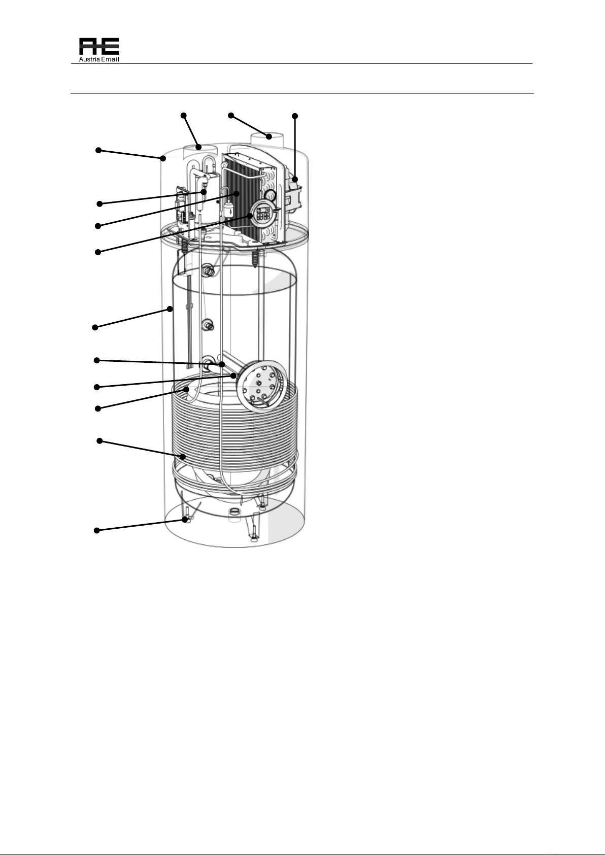
4.2 Component Parts
A
B
D
A
Air duct connection Φ150 - inlet
B
Air duct connection Φ150 - outlet
C
Heat pump housing
D
Fan
E
Compressor
F
Evaporator
G
Controller
H
DHW tank
I
Mg. Anode
J
DHW tank coil
K
Condenser
L
Leveling feet
M
Electric heater
C
E
F
G
H
I
M
J
K
L
DHW heating by means of a heat pump is a very efficient way of hot water supply. A heat pump
consists of a heat pump unit (compressor, evaporator, fan, etc.) and a water heater. The housing
of the unit is made of a resistant EPP material with thermal and sound insulation. The device has
two connections for air ducts, which enables the supply and discharge of air from an adjoining
room or from the outside. The water heater is equipped with an additional heat exchanger for the
connection of a fossil-fuel boiler, biomass boiler or solar panels.
© Austria Email AG
13
V1.0 1/2021
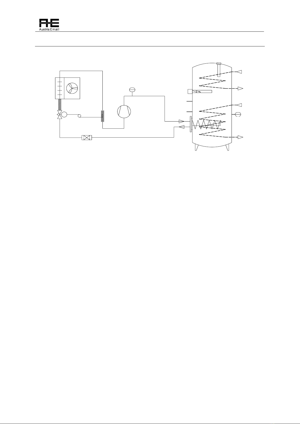
4.3 Operating Principle
56
416
16
7
3
TS
TW THP
14
10
11 12
15
8
9
1
2
13
PSH
PHP
TC
17
1. Compressor
The refrigerant circuitin a heat pump is a closed
system in which the cooling agent R 134a is
circulating as the energy carrier. When the
pressure and the temperature are low (e.g.
20°C) the refrigerant is evaporated in the heat
pump evaporator and the heat is extracted
from the air. In the compressor the refrigerant
is then compressed to a higher level, which
causes the temperature of the refrigerant to
rise above the temperature of the water in the
water tank. Next, the refrigerant transfers the
heat to the water and is then liquefied. With
the expansion of the refrigerant, whereby the
pressure and temperature of the refrigerant
are reduced to the initial value, the cycle is
concluded. This process is continuously
repeated during the heat pump's operation.
2. Condenser
3. Filter dryer
4. Expansion valve
5. Evaporator
6. Fan
7. Expansion valve sensor
8. El. heater
9. Mg. anode
10. /
11. El. heater –safety thermostat
12. Sensor –heat pump
13. High pressure switch
14. Heat exchanger –heating water
15. Water heater
16. Thermal insulation
Water Heater (hot water tank)
The water heater is enamelled on the inside with a patented technology, thermally insulated on the
outside with polyurethane and mechanically protected with steel plate. The water heater contains a
heat exchanger as standard equipment for connection to the boiler if bivalent operation of the heat
pump is selected. The water heater is also fitted with a protective Mg-anode, which prevents
corrosion of the water heater in the event of a mechanical damage to the enamel. Three levelling
feet are enclosed, which enable the placement of the device on an uneven base. For a correct
placement of the heat pump, please use a spirit level.
Additional Electric Heater
An additional electric heater with 1.5 kW of power serves to:
•heat the water quickly; the heat pump and the electric heater operate at the same time,

© Austria Email AG
14
V1.0 1/2021
•protect the evaporator from frosting; if in summertime the heat pump cannot operate due
to a low room temperature, the EH switches on,
•alternative source; in case of a failure of the heat pump unit.
Frost protection sensor
The heat pump regulator contains an air temperature sensor, which measures the temperature of the
air that flows through the evaporator. If the air temperature is below 7°C (factory-set), the sensor
switches off the HP for at least 30 minutes. If the heat pump has an integrated electric heater, the
heating is automatically reconnected using the electric heater (in summertime), or the circulation
pump of the connected boiler is switched on (in wintertime).
Safety thermostat of the electric heater
The electric heater has an integrated working and safety thermostat limited to 65 °C. The safety
thermostat switches off at 85 °C and must then be reset manually.
The safety thermostat is below the flavge cover
Unplug the heat pump from the power supply:
•Remove the flange cover.
•Press the red button on the safety
thermostat until you heat a „Click“.
•Mount the flange cover.
Control of the water temperature in the water heater
The OPTITRONIC regulation is used to monitor the heating of water to the set temperature.
Depending on the set water temperature, the regulation starts or stops the operation of the
compressor and the fan and under certain conditions it also switches on and off the electric heater or
the boiler circulation pump. The maximum set heating temperature is 55°C when operating with the
compressor. When using the “HT” key for fast heating, the temperature reaches 60°C.
High pressure control
A high-pressure safety switch is installed to prevent the occurrence of high pressure in the
refrigerant circuit and possible damages. In the event of an increased pressure, the heat pump
operation is switched off, thus preventing damage to the compressor. If he pressure in the system
drops, the heat pump automatically switches back on. In this, case error »E7« appears on the display.
Operating conditions
In normal operation, the ambient temperature should be between -7°C and +35°C. The air must be
clean and the relative humidity at +40°C should not exceed 50%. If the ambient temperature is lower,
the relative air humidity can be somewhat higher. The appliance cannot be installed at a height of
more than 2000 m above sea level, since the lower air pressure can substantially reduce the heating
capacity of the device.

© Austria Email AG
15
V1.0 1/2021
ATTENTION
The heat pump must never be installed in locations, where there may be
harmful substances present in the air, which could damage the device (stables,
storage rooms for hazardous substances, outdoors, etc.).
4.4 Technical Data
Product
Heat pump for DHW heating with air duct.
Type
WPA
Model
WPA 303 E-LF
WPA 233 E-LF
Heating capacity:
1830 W (3330 W)*
Power consumption:
440 W (1940 W)*
Max. power consumption:
560 W (60°C) (2060 W)*
El. heater:
1500 W
Voltage:
230 V a.c.
Max. additional power for circ.
pump:
300 W
COPt (EN16147; A15W55; XL)
3,0
2,9
Refrigerant:
R134a (0,9kg)
Max. water temperature:
60°C - 65°C (75°C)*
Required air flow rate:
500 m3/h
Protection class:
IPX1
Ambient air temperature:
+7 - +35°C
Water heater protection:
Mg-anode
Sound level:
56 dB(A)
El. protection
16 A, (230 V a.c.)
Max. allowed pressure in the WH:
1,0 MPa (10 bar) at 95°C
Max. allowed pressure in the heat
exchanger (heating water):
1,0 MPa (10 bar) at 110°C
Max. allowed pressure in the
cooling circuit:
2,3 Mpa (23 bar)
Heating capacity of the boiler heat
exchanger:
15 kW
Water connections:
G 1''
Circulation:
G ¾''
Air connections:
Φ 150 mm
WH volume:
300 L
225 L
Mass
175 kg
130 kg
Minimum room hight
2200 mm
2000 mm
* In case of an additional el. heater.

© Austria Email AG
16
V1.0 1/2021
5Installation
5.1 Scope of Delivery
Scope of delivery:
1. Heat pump WPA 230 ECO
2. Instructions for installation and use
3. Levelling feet
5.2 Storage
The appliance must be stored in a dry and clean place. The allowed storage temperature is between
10°C and 45°C, for a short period of time (up to 24 hrs) the temperature can reach up to 55°C.
5.3 Transport
During transportation, the heat pump is protected with protective foil and cardboard packaging to
prevent damage such as indentations and scratches. If necessary, the heat pump can be additionally
protected to avoid mechanical damages. After transportation, the device must be kept in the upright
position for at least 2 hours so that the distributed oil collects again in the compressor.
CAUTION
The appliance is too heavy for manual transportation. Such transportation can
lead to personal injuries and damages to the device. All responsibility for
possible damages is assumed by the buyer.
CAUTION
Never place the heat pump in horizontal position.
5.4 Place of Installation
The heat pump should in no case be installed in a place, where there are harmful substances present
in the air (stables, storage rooms for hazardous substances, outdoors, etc.). The minimum ceiling
height must be at least 2100 mm and the minimum room size must be 20 m3. The construction of the
device enables the heat pump to exploit the warmth of the ambient air or to supply the inlet air from
the neighbouring rooms or from the outside via air duct system. The heat pump enables the
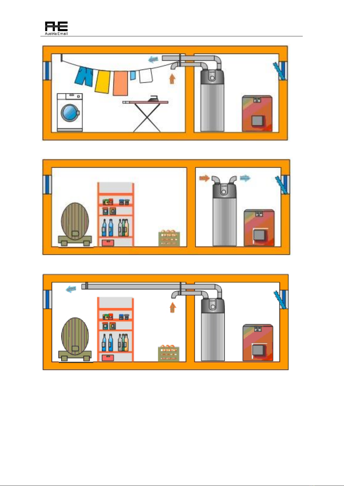
following types of ventilation, depending on the design of the piping system:
© Austria Email AG
17
V1.0 1/2021
Figure 1: Air is supplied from a neighbouring room and discharged back into the same room. Drying of linen.
Figure 2: Air supply and discharge take place in the room where the HP is installed.
Figure 3: Air is supplied from a neighbouring room and discharged back. Cooling of a storage room.
© Austria Email AG
18
V1.0 1/2021
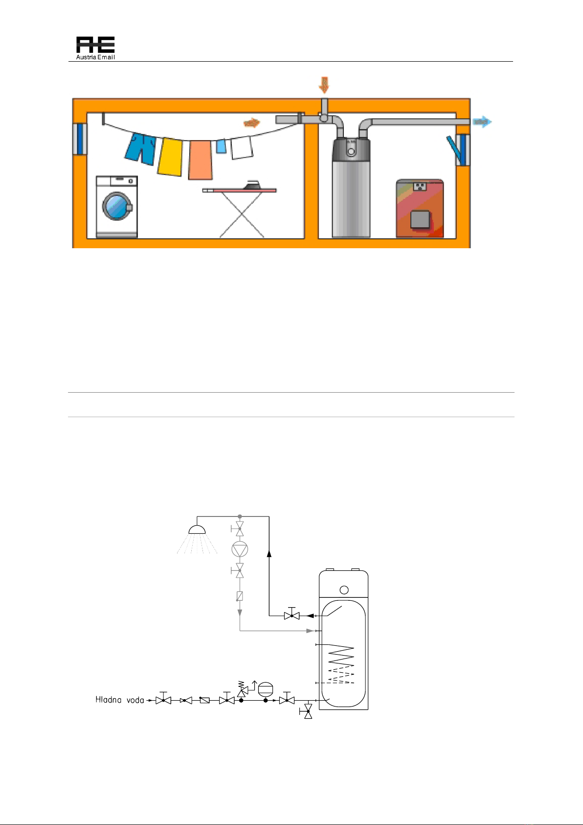
Figure 4: Air is supplied from a neighbouring room and discharged into the surroundings.
The most frequent air duct system is one, where the air is supplied from spaces with large quantities
of waste heat. Heat is extracted from the air, which is then discharged into the surroundings. Air
from kitchens, laundry rooms, bathrooms and toilets, etc. frequently contains odours and is
therefore discharged into the surroundings.
5.5 Installation
5.5.1 Hydraulic Connection
Hydraulic connection must be carried out in accordance with the current national and local
regulations which apply to the connection of water heaters. Figure below illustrates a correct
hydraulic connection of the heat pump. The maximum pressure in the piping system must not exceed
6 bar. If the tube heat exchanger inside the water heater will not be used, it must be filled with a
glycol mixture to avoid corrosion in the exchanger. The filled heat exchanger must not be closed air-
tight at both ends (pressure equalization due to temperature changes).
3
1
1
5
6
1
11
23
4
1
7
8
1. Shut-off valve
2. Pressure
reduction valve
3. Non-return
valve
4. Safety valve
5. Expansion
vessel
6. Discharge valve
7. Circulation
pump
8. Heat pump
© Austria Email AG
19
V1.0 1/2021
Expansion vessel dimensioning:
Safety valve setting [bar]
6
10
System pressure [bar]
3,0
3,5
4,0
3,0
3,5
4,0
Water heater volume [L]
Expansion vessel [L]
450
24
32
44
15
16
17
*This is only a recommendation. The exact size of the expansion vessel must be determined by the
installer/project designer according to the size of the system to which the vessel will be installed.
5.5.2 Connection of the Air Duct System
A heat pump with air-duct system enables the following:
•placement in any room large enough for the installation of the device,
•ventilation of a selected room,
•discharge of waste air or supply of fresh air from the outside.
The air duct system should be executed in such a way, that it minimizes the change of the air flow
direction. The distance between the point of air intake and the point of air discharge should not exceed
10 m. Frequent change of the air flow direction is regarded as additional air resistance, which means
that the length must be shortened. Each additional 90°pipe elbow shortens the overall length by 0,5
m. Closure elements (grates, filters, ventilation valves, etc.) in the air duct system must be taken into
account as well. Increased pressure drop in the duct system reduces the air flow. If the air temperature
is below +10°C, this can cause a slow freezing of the evaporator and thus less efficient ventilation,
which is difficult to notice.
NOTE
It is necessary to install at least one 90°pipe elbow in order to prevent the inlet
and outlet air to mix.
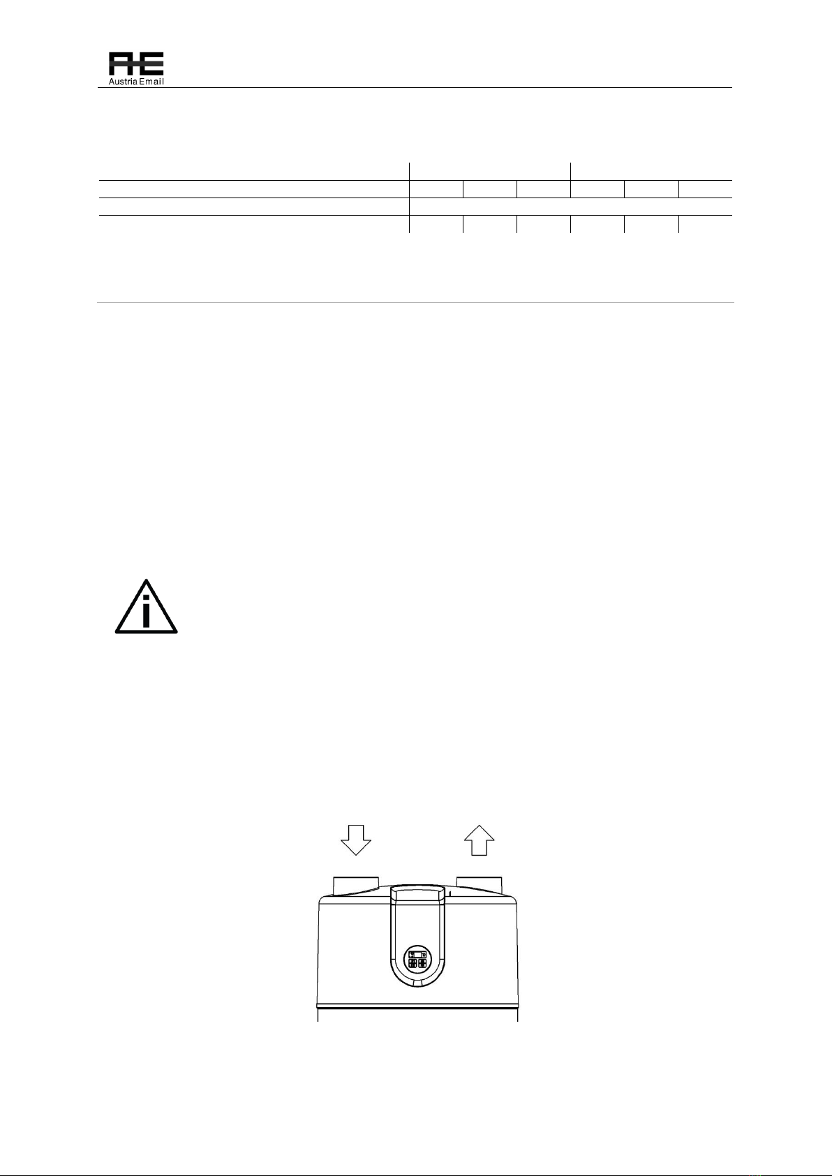
Figure below illustrates the heat pump cover with nozzles for air ducts, which are 45 mm high with an
external diameter of Φ150. Access to the internal parts is covered with a protective grid, which must
not be removed.
This manual suits for next models
1
Table of contents
Other Austria Email Heat Pump manuals

Popular Heat Pump manuals by other brands


Maritime Geothermal
Maritime Geothermal Nordic PC Series Installation and service manual

Ferroli
Ferroli EGEA 200 LT-S User and installation manual

REVELL
REVELL LWRc-8kW Operational manual

York
York FC Technical guide

Sinclair
Sinclair SWH-190-300IRE Installation and operating manual

Jandy
Jandy EE-Ti Installation & operation manual

Bryant
Bryant 575J 16T Series Installation, Start-Up and Service Instructions
 Service manual")
YMGI
YMGI VRUO-2436HP-U2B(54) Service manual

Amana
Amana AVZC18 Series Installation & service reference

Daikin
Daikin Altherma EKCBH-BAV3 installation manual

Samsung
Samsung RD060PHXEA installation manual
 specification")
EMI
EMI DFPH093 (FHP12-SHC09) specification