AUTLED NT-810-154 User manual

TD - Power Supply SC DALI & Switch Dim PRE (CC) - IP20
User Manual - 10W / 150-400mA
Item no.: NT-810-154
1. Product Description
The TD-Power Supply SC DALI & Switch Dim PRE is a dimmable constant current LED driver
for ceiling and furniture installation. Power supply and dimmer are in one housing. It can be
controlled by means of a DALI signal as well as with commercially availabel push-buttons (push,
touch or switch dim function). The ouptut current is adjustable from 150-400mA.
Suitable for emergency escape lighting systems acc. to EN50172
3. Description
2. Specifications
1. Dimmable constant curred LED driver
2. Dimming range from 1-100%
3. Dimmig and switching on and off of the LEDs by means of DALI signal or commercail
available buttons (push, touch or switch dim function)
4. The dimmer has 1 output channel and can be connected by means of resistors
150mA - 400mA output currenct can be adjusted.
5. Suitable for emergency lighting according to EN50172
6. Ideal for using linear and area lighting in office applications
7. Small design (175x43x30mm) with strain relief
Input Voltage 198-264VAC, 176-280VDC
max. Output Power 150mA-400mA (max. 10W)
Inrush Current 16A / 255µs | 230V
max. wire cross-section max. 1,5mm²
Dimensions (L x W x H) 130 x 43 x 30mm (without strain relief)
weight 125g
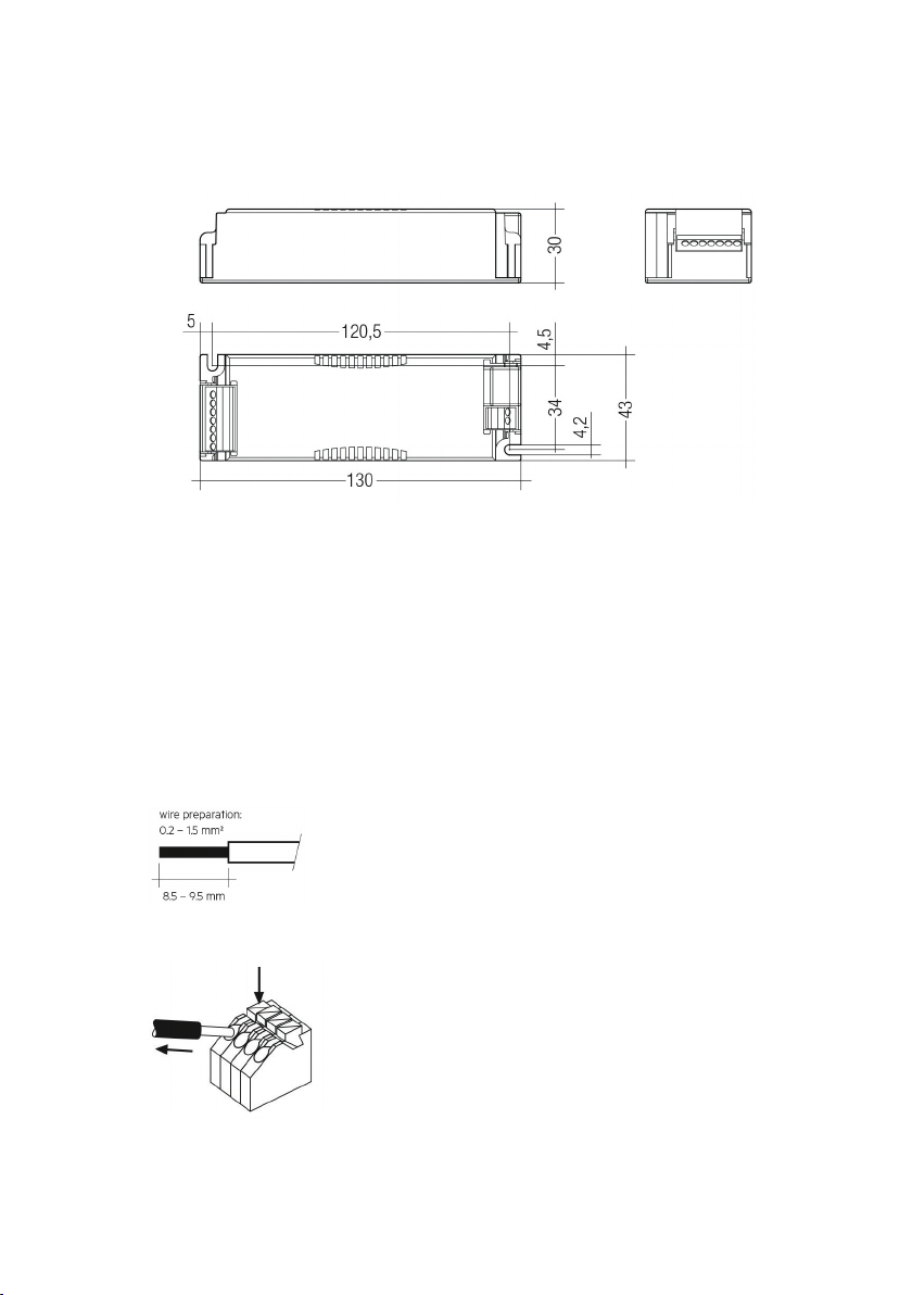
Wiring type and cross section
The wiring can be in stranded wires with ferrules or solid with a cross section of 0.2–1.5 mm².
Strip 8.5–9.5 mm of insulation from the cables to ensure perfect operation of the push-wire
terminals.
Use one wire for each terminal connector only.
Use each strain relief channel for one cable only.
6. Installation and wiring
4. Dimensions
Loose wiring
Press down the „push button“ and remove the cable from the front.
Dimensions without strain-relief

Wiring guidellines
- The cables should be run separately from the mains connections and mains cables to
ensure good EMC conditions.
- The LED wiring should be kept as short as possible to ensure good EMC.
The max. secondary cable length is 2 m (4 m circuit), this applies for LED output as well
as for I-select 2.
- Secondary switching is not permitted.
- The LED Driver has no inverse-polarity protection on the secondary side. Wrong polarity can
damage LED modules with no inverse-polarity protection.
- Wrong wiring of the LED Driver can lead to malfunction or irreparable damage.
Hot plug-in
Hot plug-in is not supported due to residual output voltage of > 0 V.
If a LED load is connected the device has to be restarted before the output will be activated
again.
This can be done via mains reset or via interface (DALI, DSI, switchDIM,
ready2mains).
Earth connection
The earth connection is conducted as protection earth (PE). The LED Driver
can be earthed via earth terminal. If the LED Driver will be earthed, protection earth (PE)
has to be used. There is no earth connection required for the functionality of the LED Driver.
Earth connection is recommended to improve following behaviour:
• Electromagnetic interferences (EMI)
• LED glowing at standby
• Transmission of mains transients to the LED output
In general it is recommended to earth the LED Driver if the LED module is mounted on earthed
luminaire parts respectively heat sinks and thereby representing a high capacity against earth.
7. Electrical values
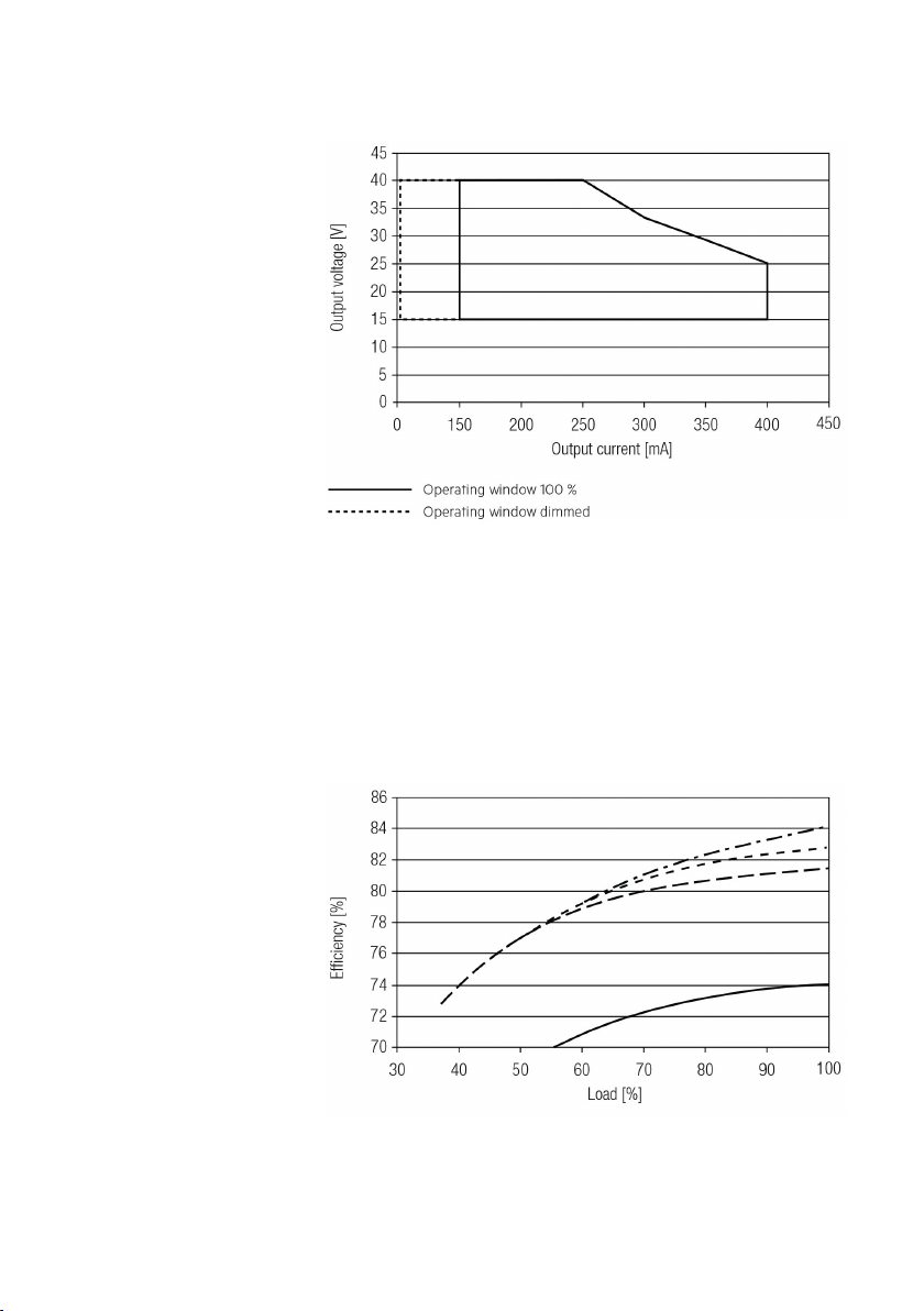
Efficiency vs load
Operating window
Make sure that the LED Driver is operated within the given window under all operating
conditions. Special attention needs to be paid at dimming and DC emergency operation as
the forward voltage of the connected LED modules varies with the dimming level, due to
the implemented amplitude dimming technology.
Coming below the specified minimum output voltage of the LED Driver may cause the
device to shut-down.
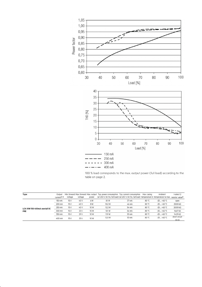
Power factor vs load
THD vs load
(without harmonic < 5mA
or 0,6% of the input current)
Specific techhical data
1) Valid at 100 % dimming level.
2) Depending on the selected output current.
3) Depending on the DALI traffic at the interface.
4) The table only lists a number of possible operating points but does not cover each
single point. The output current can be set within the total value range in 1-mA-steps.
5) Not compatible with I-select (generation 1).
6) Output current is mean value.

Maximum loading of automatic circuit breakers
Calculation uses typical values from ABB series S200 as a reference.
Actual values may differ due to used circuit breaker types and installation environment.
Harmonic distortion in the mains supply (at 230V/50Hz and full load)
Dimming
Dimming range 1 % bis 100 %
Digital control with:
• DSI signal: 8 bit Manchester Code, Speed 1% to 100% in 1,4 s
• DALI signal: 16 Bit Manchester Code, Speed 1% to 100% in 0,2 s
Programmable parameter:
Minimum dimming level = 1 %, Programmable range 1% ≤ MIN ≤ 100%
Maximum dimming level = 100 %, Programmable range 100% ≥ MAX ≥ 1%
Dimming curve is adapted to the eye sensitiveness.
Dimming is realized by amplitude dimming.
Dimming characteristic
Acc. to 61000-3-2. Harmonics < 5 mA or < 0.6% (whatever is greater) of the input current are not
considered for calculation of THD.

8. Interface / Communication
Control Input (DA/N, DA/L)
Digital DALI signal or switchDIM can be wired on the same terminals (DA/N and DA/L).
The control input is non-polar for digital control signals (DALI, DSI).
The control signal is not SELV.
Control cable has to be installed in accordance to the requirements of low voltage installations.
Different functions depending on each module.
Control input ready2mains (L, N)
The digital ready2mains protocol is modulated onto the mains signal which is wired to
the mains terminal (L and N).
switchDIM
Integrated switchDIM function allows a direct connection of a pushbutton for dimming
and switching.
Brief push (< 0.6 s) switches LED Driver ON and OFF. The dimm level is saved at power-down
and restored at power-up.
When the pushbutton is held, LED modules are dimmed. After repush the LED modules are
dimmed in the opposite direction.
In installations with LED Drivers with different dimming levels or opposite dimming directions
(e.g. after a system extension), all LED Drivers can be synchronized to 50 % dimming level by a
10 s push.
Use of pushbutton with indicator lamp is not permitted.

Adjustable current
The output current of the LED Driver can be adjusted in a certain range.
For adjustment there are three options available.
Option 1: DALI
Adjustment is done by masterCONFIGURATOR (see masterCONFIGURATOR documentation).
Option 2: I-select 2
By inserting a suitable resistor into the I-select 2 interface, the current value
can be adjusted. The relationship between output current and resistor value as follows:
R [kΩ] = 5 V / I_out [mA] x 1000
Please note that the resistor values for I-select 2 are not compatible with I-select (generation 1).
Installation of an incorrect resistor may cause irreparable damage to the LED module(s).
Option 3: ready2mains
Adjustment is done by the ready2mains programmer and the corresponding configuration
software (see ready2mains documentation).
The priority for current adjustment methods is DALI (highest priority), I-select 2,
ready2mains (lowest priority).
ready2mains – Configuration
The ready2mains interface can be used to configure the main parameters of LED Drivers
via the mains wiring, such as LED output current, CLO and DC level. These parameters can
be adjusted either via ready2mains-capable configuration software or directly via the
ready2mains programmer (output current only).
ready2mains – Dimming
ready2mains allows for mains-based group dimming, controlled via the ready2mains protocol
and appropriate dimming interfaces.
For details on the operation of ready2mains and its components see the relevant technical
information.
9. Functions

Short-circuit behaviour
In case of a short-circuit at the LED output the LED output is switched off.
After restart of the LED Driver the output will be activated again.
The restart can either be done via mains reset or via interface (DALI, DSI, switchDIM,
ready2mains).
No-load operation
The LED Driver will not be damaged in no-load operation. The output will be deactivated
and is therefore free of voltage. If a LED load is connected the device has to be restarted
before the output will be activated again.
Overload protection
If the output voltage range is exceeded the LED Driver turns off the LED output.
After restart of the LED Driver the output will be activated again.
The restart can either be done via mains reset or via interface (DALI, DSI,
switchDIM, ready2mains).
Overtemperature protection
The LED Driver is protected against temporary thermal overheating. If the temperature limit
is exceeded the output current of the LED module(s) is reduced.
The temperature protection is activated approx. +5 °C above tc max (see page 2).
On DC operation this function is deactivated to fulfill emergency requirements.
corridorFUNCTION
The corridorFUNCTION can be programmed in two different ways.
To program the corridorFUNCTION by means of software a DALI-USB interface is needed
in combination with a DALI PS. The software can be the masterCONFIGURATOR.
To activate the corridorFUNCTION without using software a voltage of 230 V has to be applied
for five minutes at the switchDIM connection. The unit will then switch automatically to the
corridorFUNCTION.
Note:
If the corridorFUNCTION is wrongly activated in a switchDIM system (for example a switch is
used instead of pushbutton), there is the option of installing a pushbutton and deactivating
the corridorFUNCTION mode by five short pushes of the button within three seconds.

switchDIM and corridorFUNCTION are very simple tools for controlling gears with conventional
pushbuttons or motion sensors.
To ensure correct operation a sinusoidal mains voltage with a frequency of 50 Hz or 60 Hz
is required at the control input.
Special attention must be paid to achieving clear zero crossings.
Serious mains faults may impair the operation of switchDIM and corridorFUNCTION.
Constant light output (CLO)
The luminous flux of a LED decreases constantly over the life-time. The CLO function ensures
that the emitted luminous flux remains stable. For that purpose the LED current will increase
continuously over the LED life-time.
In masterCONFIGURATOR it is possible to select a start value (in percent) and an expected
life-time. The LED Driver adjusts the current afterwards automatically.
Power-up/-down Fading
The power-up/-down function offers the opportunity to modify the on-/off behavior.
The time for fading on or off can be adjusted in a range of 0.2 to 16 seconds.
According to this value, the device dims either from 0 % up to the power-on level or from the
current set dim level down to 0 %.
This feature applies while operating via switchDIM, ready2mains and when switching the mains
voltage on or off. By factory default no fading time is set (= 0 seconds).
Light level in DC operation
The LED Driver is designed to operate on DC voltage and pulsed DC voltage.
For a reliable operation, make sure that also in DC emergency operation the LED Driver is
run within the specified conditions as stated in chapter “4.1 operating window”.
Light output level in DC operation: programmable 1 – 100 % (EOFi = 0.13).
Programming by DALI or ready2mains.
In DC operation dimming mode can be activated.

The voltage-dependent input current of Driver incl. LED module is depending on the used load.
The voltage-dependent no-load current of Driver (without or defect LED module) is for:
AC: < 12.4 mA
DC: < 4.5 mA
Software / programming
With appropriate software and an interface different functions can be activated and various
parameters can be configured in the LED Driver.
To do so, a DALI-USB or ready2mains programmer and the software (masterCONFIGURATOR)
are required.
masterCONFIGURATOR
From version 2.8:
For programming functions (CLO, I-select 2, power-up fading,
corridorFUNCTION) and device settings (fade time, ePowerOnLevel, DC
level, etc.). For further information see masterCONFIGURATOR manual.
10. Miscellaneous
Isolation and electric strength testing of luminaires
Electronic devices can be damaged by high voltage. This has to be considered during
the routine testing of the luminaires in production.
According to IEC 60598-1 Annex Q (informative only!) or ENEC 303-Annex A,
each luminaire should be submitted to an isolation test with 500 V DC for 1 second.
This test voltage should be connected between the interconnected phase and neutral
terminals and the earth terminal.
The isolation resistance must be at least 2 MΩ.
As an alternative, IEC 60598-1 Annex Q describes a test of the electrical strength
with 1500 V AC (or 1.414 x 1500 V DC). To avoid damage to the electronic devices this
test must not be conducted.

Conditions of use and storage
Enviromental conditions:
5 % up to max. 85 %,
not condensed
(max. 56 days/year at 85 %)
Storage temperature:
-40 °C up to max. +80 °C
The devices have to be acclimatised to the specified temperature range (ta)
before they can be operated.
Variante Switch/Touch/Push DIM
Variante DALI
DA
DA
DALI
SIGNAL
PE
L
230V~
POWER N
R
R
o
GND
TASTER
BUTTON
PE
L
230V~
POWER N
Der Ausgangsstrom kann mittels Einsteckwiderständen, Programmiergerät oder DALI eingestellt werden. Wird kein Widerstand oder Drahtbrücke zwischen den I-SELECT
Anschlüssen gesetzt, so gilt der am Gerät niedrigste Ausgangsstrom. Wird eine Drahtbrücke am I-SELECT Anschluss gesetzt, so gilt der am Gerät höchste Ausgangsstrom. Für
Einstellwerte dazwischen werden Einsteckwiderstände benötigt.
The output current can be adjusted by means of plug-in resistors, pragramming unit or DALI. Is no resistance or wire bridge set between the I-SELECT plug, the lowest output current
on the device applies. If a wire bridge is set at the I-SELECT plug, the hightest output current on the device applies. For setting values between, plug-in resistors are required.
TD Netzteil | Power Supply SC DALI
& Switch Dim PRE (CC) MM –IP20
NT-810-154 | NT-817-257
NT-825-351 | NT-845-514
LED+
POWER
IN
230V
AC/DC
DA | N
DA | L
LED–
DALI/
SWITCH
DIM
L
N
PE
Isel2-1
Isel2-2
I-SELECT
PLUG
OUTPUT
LED
TD Netzteil | Power Supply SC DALI
& Switch Dim PRE (CC) MM –IP20
NT-810-154 | NT-817-257
NT-825-351 | NT-845-514
LED+
POWER
IN
230V
AC/DC
DA | N
DA | L
LED–
DALI/
SWITCH
DIM
L
N
PE
Isel2-1
Isel2-2
I-SELECT
PLUG
OUTPUT
LED LED Platinen Modul
LED PCB Module
+
–
LED Platinen Modul
LED PCB Module
+
–
11. Wiring diagram
Table of contents


