KEBCO Combivert R6 User manual

COMBIVERT
GB Instruction Manual
Power Supply and Regenerative Unit
Type R6-S Type 25R6S3R-xxxx
Mat.No. Rev.
00R6SEB-KR01 2B


Table of Contents
1. Introduction..................................................................................................... 5
1.1 Preface..................................................................................................................................5
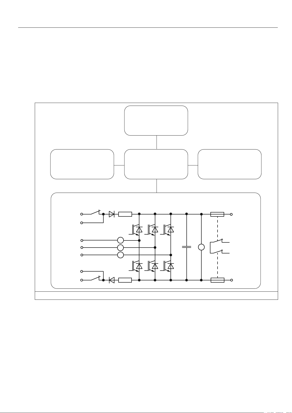
1.2 Product description.............................................................................................................5
1.3 Validity and liability .............................................................................................................7
1.4 Copyright..............................................................................................................................7
1.5 Speciedapplication...........................................................................................................7
1.5.1 Standard operation ................................................................................................................8
1.5.2 Abnormal operation ...............................................................................................................8
1.6 Unitidentication ................................................................................................................9
2. Safety Instructions ....................................................................................... 10
2.1 General instructions..........................................................................................................10
2.2 Transport, storage and installation..................................................................................10
2.3 Electrical connection......................................................................................................... 11
2.4 EMC instructions ...............................................................................................................14
2.5 EMC conform installation .................................................................................................14
3. Technical Data .............................................................................................. 15
3.1 Overload (OL) function......................................................................................................16
3.2 Operating conditions.........................................................................................................17
3.3 Accessories........................................................................................................................18
3.4 Options ...............................................................................................................................19
3.4.1 Ferrite rings..........................................................................................................................20
3.5 Dimensions and weights...................................................................................................21
3.5.1 Dimensions air cooling system mounted version.................................................................21
3.5.2 Commutation reactor / mains choke ....................................................................................22
3.5.3 Radiointerferencelter(side-mounted) ..............................................................................23
3.5.4 Synchronization unit ............................................................................................................25
3.5.5 Fuse holder with cover.........................................................................................................26
4. Installation..................................................................................................... 27
4.1 EMC-compatible control cabinet installation..................................................................27
4.2 Installation instructions ....................................................................................................27
4.3 Connection of the COMBIVERT R6 ..................................................................................28
4.3.1 General description of inverter input terminals ....................................................................28
4.3.2 Connection terminals of the power circuit............................................................................30
4.3.3 Connections of the control board.........................................................................................32
4.3.4 Connection of the synchronization unit................................................................................33
4.4 Connection power unit R6-S without UL .........................................................................34
4.4.1 Powersupplyandregenrativeoperationatinvertercurrent≤invertercurrentofone
COMBIVERT R6-S without UL ............................................................................................34
4.5 Connection power unit R6-S with UL...............................................................................36
4.5.1 Powersupplyandregenrativeoperationatinvertercurrent≤invertercurrentofone
COMBIVERT R6-S with UL .................................................................................................36
4.5.2 Power supply and regenerative operation at parallel operation with one frequency
inverter.................................................................................................................................37
GB - 3
Table of Contents

4.5.3 Power supply and regenerative operation at parallel operation with a further regenera-
tive unit ................................................................................................................................37
4.6 Connection of the control board version S.....................................................................38
4.6.1 Assignment of the control terminal strip X2A.......................................................................38
4.6.2 Assignment of the socket X2B.............................................................................................39
4.6.3 Assignment of the terminal block X2C.................................................................................39
4.6.4 Wiring example ....................................................................................................................40
5. Operation of the Unit.................................................................................... 41
5.1 Operation with PC und system software COMBIVIS ......................................................41
5.2 Switch-on procedure .........................................................................................................41
5.3 Parameter summary ..........................................................................................................42
5.4 Monitoring and analysis parameters ...............................................................................43
5.5 Special adjustments ..........................................................................................................47
A. Appendix A.................................................................................................... 50
A.1 Dimensioning power supply and regenerative units .....................................................50
A.2 DC link capacitors of KEB frequency inverters ..............................................................51
A.3 Decoupling diodes.............................................................................................................53
A.3.1 Assignment ..........................................................................................................................53
A.3.2 Dimensions of the decoupling diodes ..................................................................................54
B. Appendix B.................................................................................................... 55
B.1 Certication........................................................................................................................55
B.1.1 CE Marking ..........................................................................................................................55
B.1.2 ULCertication ....................................................................................................................55
List of Figures
Figure 1: Block diagram of the COMBIVERT R6S ...................................................................6
Figure2: Overload(OL)function............................................................................................16
Figure 3: COMBIVERT R6 with fan heat sink ........................................................................21
Figure 4: Mains choke............................................................................................................22
Figure5: Radiointerferencelter24E6T60-3000(side-mounted).........................................23
Figure6: Radiointerferencelter25E4T60-1001(side-mounted).........................................24
Figure 7: Synchronization unit................................................................................................25
Figure 8: Fuse holder .............................................................................................................26
Figure 9: EMC-compatible control cabinet installation ...........................................................27
Figure 10: General description of input terminals at KEB inverter ...........................................29
Figure 11: Description of the input terminals of the COMBIVERT R6......................................30
Figure 12: Connection terminals of the power circuit ...............................................................31
Figure 13: Connection terminals of the control board ..............................................................32
Figure 14: RJ45 socket for phase synchronization and temperature sensor ...........................33
Figure 15:
Powersupplyandregenerativeoperationatinvertercurrent≤currentofoneCOMBIVERTR6-S
35
Figure 16:
Powersupplyandregenerativeoperationatinvertercurrent≤currentofoneCOMBIVERTR6-S
37
Figure 17: RJ45 socket ............................................................................................................39
Figure 18: Wiring example R6-S ..............................................................................................40
Figure 19: Dimensioning power supply and regenerative units ...............................................50
Figure 20: Dimensions of the decoupling diodes .....................................................................54
GB - 4
Table of Contents

1. Introduction
1.1 Preface
First we would like to welcome you as a customer of KEB and congratulation to the purchase
of this product. You have decided for a product on highest technical niveau.
The enclosed documents as well as the indicated hard- and software are developments of
the KEB Automation KG. Errors excepted. KEB Automation KG has created these docu-
ments and the hard- and software to the best of knowledge, but they assume no liability that
thespecicationswillprovidethebenetssoughtbytheuser.KEBAutomationKGreserves
therighttochangespecicationswithoutpriornoticeortoinformthirdparties.Thislistisnot
exhaustive.
Theusedpictogramshavefollowingsignicance:
Danger
Warning
Caution
Attention
absolutely observe
Information
Help
Tip
1.2 Product description
This instruction manual describes the power supply and regenerative unit KEB COMBIVERT
R6-S. The COMBIVERT R6-S has the following features.
In power supply operation
• converts a three-phase input voltage into DC voltage.
• supplies single KEB frequency inverter or via DC interconnection.
• can be parallel connected if higher power supply is required.
In regenerative operation
• refeeds excess energy from regenerative operation into the supply system.
• replaces braking resistor and braking transistor.
• reduces the heat loss dissipation compared to the braking resistor
• improves the energy balance
• is environmentally friendly and space-saving
• is economically
GB - 5
Introduction

The COMBIVERT R6-S is generally protected against overcurrent, ground fault and tempera-
ture. The internal DC fuses protect the DC circuit against short-circuit to the line side. The
following accessories are necessary for operation with the COMBIVERT R6-S:
• Mains choke
• HFlter(forobservanceofEMCstandard)
+
X1A ++
X1A --
X1C L1
X1A L12
X1B L2
X1C L2
X1B L1
V
X1C Fo.1
X1C Fo.2
A
A
A
K2
K2
X1A L22
X1A L32
Power unit
Connection syn-
chronization(net-
workcoverage)
Control communication
Connection I / O
Interface communi-
cation
Figure 1: Block diagram of the COMBIVERT R6S
GB - 6
Introduction

1.3 Validity and liability
Application and use of our units in the target products is outside of our control and
therefore exclusively in the area of responsibility of the machine manufacturer.
Theinformationcontainedinthetechnicaldocumentation,aswellasanyuser-specicadvice
in spoken and written and through tests, are made to best of our knowledge and information
about the application. However, they are considered for information only without responsibil-
ity. This also applies to any violation of industrial property rights of a third-party.
Selection of our units in view of their suitability for the intended use must be done generally
by the user.
Inspections and tests can only be done by the machine manufacturer within the framework
of the application. Inspections and tests must be repeated, even if only parts of hardware,
softwareortheunitadjustmentaremodied.
Unauthorized opening and improper tampering can lead to bodily injuries or liability insur-
ances and this cause loss of the warranty. Original spare parts and authorized accessories
by the manufacturer serve as security. The use of other parts excludes liability for the conse-
quences arising out of.
Thesuspensionofliabilityisespeciallyvalidalsoforshutdowndamages,lostprot,dataloss
or other consequential damages. This is also valid, if we have been referred to the possibility
of such damages.
Should any part of this agreement be invalid for any reason, it is to be replaced with a cor-
responding text, which is valid and equivalent to the intended meaning. The rest of the agree-
ment shall remain unaffected and valid.
1.4 Copyright
The customer may be use the instruction manual as well as further enclosed documents or
parts from it for internal purposes. KEB has the copyrights and they remain effective also
to the full extent. All rights reserved. KEB®, COMBIVERT®, KEB COMBICONTROL® and
COMBIVIS® are registered trademarks of KEB Automation KG. Other wordmarks or/and
logosaretrademarks(TM)orregisteredtrademarks(®)oftheirrespectiveownersandare
listedinthefootnoteontherstoccurrence.Whencreatingourdocumentswepayattention
with the utmost care to the rights of third parties. Should we have not marked a trademark or
breach a copyright, please inform us in order to have the possibility of remedy.
1.5 Speciedapplication
The COMBIVERT R6-S serves exclusively for the supply of frequency inverters with DC input
and/or regeneration of excess energy into the supply system. The operation of other electrical
consumers is prohibited and can lead to malfunctions or to the destruction of the units.
The used semiconductors and components of KEB are developed and dimensioned for the
use in industrial products. If the product is used in machines, which work under exceptional
conditions or if essential functions, life-supporting measures or an extraordinary safety step
mustbefullled,thenecessaryreliabilityandsecuritymustbeensuredbythemachinebuild-
er. The operation of our products outside the indicated limit values of the technical data leads
to the loss of any liability claims.
GB - 7
Introduction

All control card outputs of the R6 are „one-channel, no diagnostic coverage and therefore not
safe“ according to ISO 13849. If required, additional protective measures must be met by the
user.
1.5.1 Standard operation
Generally the power supply and regenerative unit is a DC supply. If the DC voltage increases
to a value above the peak value of the mains voltage, regeneration of the current into the
mainsoccursautomatically.TheregenerativelevelcanbedenedwithparameterCP.34or
cS.02. The mains voltage is analog measured. Regeneration occurs by square-wave current
curvewhichcorrespondsinphasepositiontothecurrentowperiodofaB6bridgecircuit.
Regenerationiscompletediftheregenerativeandpulsofflevel(CP.32orcS.06)isfallen
below.
1.5.2 Abnormal operation
When exceeding the permissible limit values for voltage, current or temperature the current
owbetweenDClinkandmainsisblockedduringregeneration.Anappropriateerrormes-
sage is also displayed during supply. The unit must be disconnected from the supply system
or the load must be switched off in case of overcurrent or overload. This can be done by
opening the control release of the frequency inverter.
At factory setting the modulation is switched off in case of a net phase failure and error mes-
sage E.nEt is displayed.
Special adjustments from KEB are necessary if the modulation and/or the standard operation
shouldstartagainwithinadenedtimeincaseofreturnofpowersupply.
GB - 8
Introduction

1.6 Unitidentication
2 5 . R 6 . S 3 R - 9 0 0 A
Type A: Standard
D. ext. fan power supply
H: Water cooling
Design 0: Standard
reserved 0: Standard 1: modiedstandard
Voltage 9: 3-ph.; 400 V; AC
Housing R
Options 3: Precharging, DC fuses
Control S: 2B.R6
Series R6
Unit size 25
GB - 9
Introduction

2. Safety Instructions
2.1 General instructions
Electric
shock
COMBIVERT R6 power supply und regenerative units contain dangerous volt-
ages which can cause death or serious injury.
COMBIVERT R6 can be adjusted by way that energy is regenerated into the
supply system in case of power failure at regenerative operation. Therefore a
dangerous high tension can be in the unit after switching off the supply system.
Before working with the unit check the isolation from supply by measure-
ments in the unit.
Care should be taken to ensure correct and safe operation to minimise risk to
personnel and equipment.
Only quali-
edelectro-
personnel
All work from the transport, to installation and start-up as well as maintenance
mayonlybedonebyqualiedpersonnel(IEC364and/orCENELECHD384
andIEC-Report664andnotenationalsafetyregulations).Accordingtothis
manualqualiedstaffmeansthosewhoareabletorecogniseandjudgethe
possible dangers based on their technical training and experience and those
withknowledgeoftherelevantstandardsandwhoarefamiliarwiththeeldof
power transmission.
Observe
standards
The COMBIVERT R6 must not be started until it is determined that the installa-
tioncomplieswith2006/42/EC(machinedirective)(noteEN60204).
The COMBIVERT R6 meets the requirements of the Low-Voltage Directive
2006/95/EC.TheharmonizedstandardoftheseriesEN61800-5-1(VDE0160)
is used.
This is a product of limited availability in accordance with IEC 61800-3. This
product may cause radio interference in residential areas. In this case the op-
erator may need to take corresponding measures.
2.2 Transport, storage and installation
The storage of the COMBIVERT must be done in the original packing. It is to be protected
against humidity and excessive cooling and thermal effect. A long-distance transport must be
carriedoutintheoriginalpacking.Itistobesecuredagainstimpactinuence.Observethe
markingonthenalpacking!AfterremovingthenalpackingtheCOMBIVERTmustbeshut
down on a stable base.
GB - 10
Safety Instructions

Protect
against
accidental
contact
The COMBIVERT R6 must be protected against invalid loading. Components
and covers must not be bent or moved as this may affect insulation distances.
The units contain electrostatic sensitive devices which can be destroyed by
inappropriate handling. For that reason the contact of electronic devices and
contacts is to be avoided. The equipment must not be switched on if it is dam-
aged as it may no longer comply with mandatory standards.
Make sure that during installation there is enough minimum clearance and
enough cooling. Climatic conditions must be observed in accordance with the
instruction manual.
Hot surface
Heat sinks can reach temperatures, which can cause burns when touching. If
in case of structural measures a direct contact cannot be avoided, a warning
notice "hot surface" must be mounted at the machine.
2.3 Electrical connection
Note capaci-
tor
discharge
time
Before any installation and connection work, the system must be switched off
and secured.
After clearing the DC link capacitors are still charged with high voltage for
a short period of time. The unit can be worked on again, after it has been
switched off for 5 minutes.
Secure
isolation
The terminals of the control terminal strip are securely isolated in accordance
with EN 61800-5-1. With existing or newly wired circuits the person install-
ing the units or machines must ensure that the requirements are met. With
frequency inverters that are not isolated from the supply circuit all control
linesmustbeincludedinotherprotectivemeasures(e.g.doubleinsulationor
shielded,earthedandinsulated).
Voltage
with re-
spect to
ground
The connection of COMBIVERT R6 is allowed to:
symmetricalmainswithaphasevoltage(L1,L2,L3)withrespecttoneutral
conductor/ground(N/PE)ofmaximum305V.
Stationary
connection
TheCOMBIVERT R6isdesignedforxedconnection,since discharge cur-
rentsof>3.5mAoccurespeciallywhenusingtogetherwithEMIlters.There-
fore,therequirements orinstructionsfromEN60204-1(VDE0113)andEN
61800-5-1(IEC0160-5-1)mustbeobserved.
GB - 11
Safety Instructions

Insulation
measure-
ment
When doing an insulation or voltage measurement in accordance with in
EN 60204-1 / VDE 0113-1, the power semiconductor of the unit and existing
radiointerferenceltersmustbedisconnectedbecauseofthedangerofde-
struction. This is permissible in compliance with the standard, since all inverters
are given a high voltage test in the end control at KEB. In the case of special
requirements please contact KEB.
Different
earth po-
tentials
When using components without isolated inputs/outputs, it is necessary that
equipotentialbondingexistsbetweenthecomponentstobeconnected(e.g.by
compensatingcable).Disregardcancausedestructionofthecomponentsby
the equalizing currents.
Prevent
disturbanc-
es
A trouble-free and safe operation of the COMBIVERT R6 is only guaranteed
when the connection instructions below are strictly followed. Incorrect opera-
tion or damage may result from incorrect installation.
• Pay attention to mains voltage.
• Installpowercablesandcontrolcablesseparately(>15cmseparation).
• Use shielded / twisted control lines. Lay shield at one side to COMBIVERT
R6-StoPE!
• Only use suitable circuit elements to control the logic and analog inputs,
whose contacts are rated for extra-low voltages.
• Housing of the COMBIVERT R6 must be well earthed. Screens of larger
power cable must be directly and securely attached to both the inverter PE
terminalandthemotorgroundterminal(removepaint).
• Ground the cabinet or the system earth star point with the shortest connec-
tiontomainsearth.(avoidearthloops)!
• UseexclusivelythelinecommutationthrottlespeciedbyKEB.
• The maximum DC current of the R6-S must not be exceeded.
• If several frequency inverters are connected to the COMVIBERT R6-S, the
max. permissible DC link capacities of all connected frequency inverters
mustbeconsidered(seetechnicaldata).
Automatic
restart of
operation
The COMBIVERT R6 can be adjusted by way that the inverter restarts auto-
maticallyafteranerrorcase(e.g.phasefailure).Systemdesignmusttakethis
into account, if appropriate, and additional monitoring or protective features
added where necessary.
GB - 12
Safety Instructions

Condition-
ally short-
circuit proof
TheCOMBIVERTR6isconditionallyshort-circuitproof(VDE0160).Afterre-
setting the internal protection devices, the function as directed is guaranteed.
Exception:
• Earth fault or short circuits at the output in regenerative operation can lead
to a defect in the unit.
• If earth fault or short circuits occur in power supply operation, semi-conduc-
tor protection is only limited.
Cyclic acti-
vation and
deactiva-
tion
With applications requiring the COMBIVERT R6 to be switched on and off cycli-
cally, maintain an off-time of at least 5 min. If you require shorter cycle times
please contact KEB. Switching off during the initialization phase can cause
undenedconditions.
RCD (resid-
ual current
operated
circuit-
breaker)
When using systems with RCD, the instructions or the requirements of VDE
0100-T530(IEC60364-5)mustbeobserved.Therecommendedtrippingcur-
rent of RCD type "B" is 300 mA.
GB - 13
Safety Instructions

2.4 EMC instructions
COMBIVERT R6-S represent electrical equipment designed for use in industrial and com-
mercial units.
In accordance with the EMC directive 2014/30/EU, these devices are with the meaning of the
directive components to be further processed by the respective machine and unit manufac-
turer and are not operable independently.
The person installing / operating the machine / unit is obliged to proove the protective meas-
ures demanded by the EMC directive are complied with. The prescribed ratings can usually
becompliedwithwhenusingtheradiointerferencevoltageltersspeciedbyKEBandwhen
observing the following measures and installation guidelines.
2.5 EMC conform installation
TheCOMBIVERTR6isdesignedtobeusedinthesecondenvironmentasdenedinEN
61800-3(unitwithitsownsupplytransformer).Takeadditionalltermeasureswhenusing
itintherstenvironment(residentialandcommercialareaconnectedtopubliclow-voltage
mains)!
• Installthecontrolcabinetorsysteminanappropriateandcorrectlyway(seechapter„EMC
conformcontrolcabinetinstallation“).
• To avoid coupled-in noises, separate supply lines, DC lines, motor lines, control and data
lines(low-voltagelevel<48V)andleaveaspaceofatleast15cmbetweenthemwhen
installing.
• In order to maintain low-resistance high frequency connections, earthing and shielding, as
wellasothermetallicconnections(e.g.mountingplate,installedunits)mustbeinmetal-
to-metal contact with the mounting plate, over as large an area as possible. Make ground
connectionswithasurfaceaslargeaspossible(earthingstrips).
• Only use shielded cable with copper or tin-plated braid, since steel braid is not suitable for
high frequency ranges. The screen must always be installed on the compensating rail and
fastened with clips or guided through the wall of the housing. Do not elongate the screen
end(pigtails)withindividualconductors!
• Ifexternalinterferencesuppressionltersareused,thenthesemustbeinstalledasclose
aspossibleto(<30cmfrom)theinterferencesourceandinmetal-to-metalcontactwiththe
mouting plate, over as large an area as possible.
• Alwaysequipinductivecontrolelements(contactors,relaysetc.)withsuppressorssuchas
varistors, RC-elements or damping diodes.
• All connections must be kept as short as possible and as close as possible to the earth, as
freeoatinglinesworkasactiveandpassiveaerials.
• Keepconnectioncablesstraight(donotbundle).Installanon-assignedwireatonesidesto
the protective earth conductor.
• Theowandreturncircuitmustbetwistedwhen the linesarenotshielded,inorderto
dampen common-mode noise.
• The cable for phase synchronization between mains choke and COMBIVERT R6-S may
not exceed a cable length of 1 m.
• Further information can be found in the internet, see „www.keb.de“.
GB - 14
EMC instructions

GB - 15
Technical Data
3. Technical Data
Unit size 25
Housing size R
Phases 3
permitted mains forms 5) TN, TT
Rated voltage [V] 400
Mains voltage range [V] 305…528
Mains frequency [Hz] 50 / 60 ±2
DC voltage range [VDC] 420…747
Regenerative operation
Output rated power Sn [kVA] 153
Rated active power [kW] 140
Max. power output [kVA] 230
Max. active power [kW] 210
Regenerative rated current *) [A] 221(184)
Regenerative DC current 1) [ADC] 270
Overloadcurrent(E.OL)60s 2) [A] 331
Max. regenerative DC current 60 s [ADC] 405
Power supply operation
Input rated power Sn [kVA] 153
Rated active power [kW] 140
Max. input power [kVA] 230
Max. active power [kW] 210
Rated supply current *),3) [A] 221(184)
DC supply current 1) [ADC] 270
Overloadcurrent(E.OL)60s [A] 331
Max. DC supply current 60s [ADC] 405
Overloaddisconnection(E.OL) [%] 160
Overvoltageswitch-off(E.OP) [VDC] 840
Output rated voltage [VDC] 540
Max. permissible DC link capacity 4) [mF] 50(400Vclass)35(480Vclass)
Max.permissibletotalloadcurrentatprecharging(I_
LSF) [AAC]≤4
I2t Integral of the limiting load of the semiconduc-
tor [A2s] 39000
Max. permissible mains fuse type gR / aR [A] 315
Permissiblemainsfuse(nodeltapowersystem) Siemens 3NE8731 /
Eaton Bussmann 170M1372 or 170M1422
Permissiblemainsfuse(nodeltapowersystem)forUL Ferraz Shawmut HSJ300, rated 300A / 600Vac
Max. permissible DC fuse Bussmann Type aR see options
Short-circuitfactorattheconnectionpoint(Skn/Sn)or(Sscp/Sn) 15<Skn“ / Sn<350
Power loss at nominal operating [W] 1300
Max. heat sink temperature [°C] 88
*) ThevaluesinbracketsmustbeobservedwhenULapprovalisrequired!
1) Lay two connection cables parallel at supply and regenerative current > 230 A DC.
2) Theoverloadcurrentisspeciedfor1minute.Theoverloadcycleis300seconds.Thiscorrespondstodutyclass2
EN 2-60146-1.
3) The current data are based on a fundamental frequency component of g=0.95. The fundamental frequency com-
ponent or the effective value of the input current is dependent on load and line supply conditions. At uncontrolled
B6convertersthephaseanglecosφ1canbesettoone,sothevalueofthefundamentalfrequencycomponentsis
equal to the value of the power factor.
4) Please contact KEB for higher values.

GB - 16
Technical Data
5) Connection to IT and delta power systems after consultation KEB.
VoltagestabilizationmustbeactivatedattheinverterifaharmoniclterisusedIfaharmoniclterisused,volt-
age stabilization must be activated for the inverter which is connected to the DC circuit.
Exceeding of the max. rechargeable DC link capacity can lead to a defect.
A load removal in the DC link circle may be done only after the message „ready“.
If the control release is set when switching off the mains, this can lead to an overcurrent error and the lifetime of
the module can be reduced.
The load must be disconnected in case of overcurrent or overload.
The device must be disconnected from the mains supply if a mains fuse has triggered.
3.1 Overload (OL) function
105 110 120 130 140 150 160
100
150
200
250
270
60
Release time [s]
Load [%]
Figure 2: Overload (OL) function

GB - 17
Technical Data
3.2 Operating conditions
Standard Standard/
class
Instructions
Denitionaccordingto
EN 61800-2 Inverter product standard:
ratedspecications
EN 61800-5-1 Inverter product standard:
general safety
Site altitude
max. 2000 m above sea level
(withsitealtitudesover1000maderatingof
1 % per 100 m must be taken into considera-
tion)
Ambient conditions during operation
Climate Temperature
EN 60721-3-3
3K3
extended to -10…45 °C
(withtemperatureover45°Ctomax.55°C
a derating of 5 % per 1 K must be taken into
consideration)
Humidity 3K3 5…85%(withoutcondensation)
Mechanical Vibration 3M1
max.amplitudeofavibration1mm(5…13Hz)
max. acceleration amplitude 7 m/s²
(13…200Hz)
Contamination Gas 3C2
Solids 3S2
Ambient conditions during transport
Climate Temperature
EN 60721-3-2
2K3
Humidity 2K3 (withoutcondensation)
Mechanical Vibration 2M1 max.vibrationamplitude3.5mm(2…9Hz)
max.accelerationamplitude15m/s²(9…200Hz)
Surge 2M1 max. 100 m/s²; 11 ms
Contamination Gas 2C2
Solids 2S2
Ambient conditions for the storage
Climate Temperature
EN 60721-3-1
1K4
Humidity 1K3 (withoutcondensation)
Mechanical Vibration 1M1 max.amplitudeofavibration1mm(5…13Hz)
max.accelerationamplitude7m/s²(13…200Hz)
Surge 1M1 max. 100 m/s²; 11 ms
Contamination Gas 1C2
Solids 1S2
Type of protection EN 60529 IP20
Environment IEC 664-1 Pollution degree 2
Denitionaccordingto EN 61800-3 Inverter product standard: EMC
EMC emitted interference
Cable-based interferences EN 55011 C2 withEMClterandferritupto100mlinelength
Radiated interferences EN55011 C2 withEMClterandferrit
Interference immunity
Electro-static discharge EN 61000-4-2 8 kV AD(airdischarge)andCD(contactdischarge)
Burst - control lines + bus EN 61000-4-4 2 kV
Burst - mains supply EN 61000-4-4 4 kV
Surge - mains supply EN 61000-4-5 1 / 2 kV Phase-phase / phase-ground
Immunity to conducted
disturbances,
induced by radio-frequency
elds
EN 61000-4-6 10 V 0.15-80 MHz
Electromagneticelds EN 61000-4-3 10 V/m
Voltage variation / voltage drop EN 61000-2-1 +10 %, -15 %; 90 %
Voltage unsymmetries /
frequency changes EN 61000-2-4 3 %; 2 %

GB - 18
Technical Data
3.3 Accessories
Unit size 25
Rated voltage 400 V
Commutation choke 25Z1B04-1000
Synchronization unit
00R6940-2407
Control cabinet installation; max. distance to the power supply
and regenerative unit 1m
Sync cable
00F50C3-4010
Length 1 m
for connection of the synchronization unit with R6 regenerative
unit

GB - 19
Technical Data
3.4 Options
Unit size 25
HF radio interference
lter(EMC)
For an ED of max. 82 % -> 24E6T60-3000
For an ED of 100 % -> 25E4T60-1001
in accordance with EN 61800-3
C2(onlywithferriterings)
C1(afterconsultationwithKEB)
DC fuses 690V / 400A Mat.No. 009025H-4651
Micro switch for fuse
009025H-4651 0090278-0001
Fuse holder for NH00
and NH000 fuses 0090574-0001
Harmoniclter
(noULcertication)
25Z1C04-1000 2)
Please contact KEB for data to the THD value at regenerative
operation in accordance with EN 61800-2-12.
Harmoniclter
(withULcertication)
Compliance with the IEEE519 requirements at a 480V / 60Hz
mainsispossiblewiththefollowingharmoniclter:
22Z1C05-1000, 23Z1C05-1000, 24Z1C05-1000, 25Z1C05-
1000
Operators Digital operator, interface operator
Bus operators CAN®,ProBus®, INTERBUS®, EtherCAT®, Ethernet®, Sercos,
ModBus, PROFINET®3), LCD, Devicenet, HSP5
1) The ON time ED refers to the regenerative unit R6-S
2)
Dependingontheload,thefollowingharmonicltersarealsopossiblewiththetechni-
cal data given therein:20Z1C04-1000, 21Z1C04-1000, 22Z1C04-1000, 23Z1C04-1000,
24Z1C04-1000
3) ProNetfromoperatorrmwareV3.4of30.01.2015
CANopen® is a registered trademark of the CAN in AUTOMATION - International Users and Manufacturers
Group e.V
INTERBUS® is a registered trademark of Phoenix Contact GmbH & Co. KG.
EtherCAT® is a registered trademark and patented technology licensed by Beckhoff Automation GmbH, Ger-
many
Industrial Ethernet® is a registered trademark of Siemens AG
PROFBUS® is a registered trademark of Siemens AG
PROFINET® is a registered trademark of Siemens AG

GB - 20
Technical Data
3.4.1 Ferrite rings
Ferrite rings are used for the reduction of the cable-based and radiated interferences. For a
high damping, the ferrite rings are attached as close as possible to the interference source,
i.e. at the DC and at the motor output terminals of the frequency inverter. The conductors
must passed through the ferrite core for the use as current-compensated choke. PE must be
passed outside. Further information can be taken from the provided documentation. Which
ferrite ring shall be used is dependent on the used cable cross-section.
Part number Nominal size in mm Inside diameter in mm
0090396-2621 R 42/26/18 24.9
0090390-5241 R 56/32/18 29.5
0090395-3820 R 63/38/25 36.0
0090395-5222 R 87/54/30 54.5
0090395-5520 R 102/66/15 64.5
Other manuals for Combivert R6
4
Table of contents
Other KEBCO Power Supply manuals

KEBCO
KEBCO combivert R6-S User manual

KEBCO
KEBCO combivert R6-S User manual

KEBCO
KEBCO combivert R6-S User manual

KEBCO
KEBCO Combivert R6 User manual

KEBCO
KEBCO Combivert R6 User manual

KEBCO
KEBCO Combivert R6 User manual

KEBCO
KEBCO COMBIVERT F5 User manual

KEBCO
KEBCO combivert R6-S User manual

KEBCO
KEBCO COMBIVERT R5-C User manual
Popular Power Supply manuals by other brands

SFC Energy
SFC Energy Efoy Pro 600 Control guide

Paradyne
Paradyne FrameSaver 9620 installation instructions

Elektro-Automatik
Elektro-Automatik PSI 9000 DT Series operating guide

Fracarro
Fracarro MINIPOWER 12 operating instructions

Sorensen
Sorensen DLM 5-75 Operation manual

Amada
Amada 125DP Operation manual