Auto Crane 600661 User manual

MODEL RS60AC
AIR COMPRESSOR
OPERATORS, MAINTENANCE
AND PARTS MANUAL
APPLIES TO SERIAL NUMBERS
600661 AND EARLIER
THIS MANUAL NO LONGER REPRESENTS
CURRENT PRODUCTION
P/N: 304173
4/7/2010 MCM

4
OPERATORS, MAINTENANCE, AND PARTS MANUAL
AUTO CRANE MODEL RS60AC
TABLE OFCONTENTS
Operation & Maintenance Section
Specifications ...................................................................................................................... 6
Safety .......................................................................................................................... 7 - 11
CompressorTerminology .................................................................................................. 12
Description of Components....................................................................................... 13 - 16
Inspection, Lubrication, and Maintenance ................................................................. 17 - 24
Troubleshooting ......................................................................................................... 25 - 27
Compressor Operation.............................................................................................. 28 - 29
Parts and Illustration Section.................................................................................... 30 - 38
Recommended Spare Parts............................................................................................... 39
ServiceQuestionnaire........................................................................................................ 40
Instructional Procedures For Installation ................................................................... 41 - 44
6
SPECIFICATIONS
GISP051@YREVILEDMFC5406
rosserpmoCotdeepStupnI MPR MPG
0051 @01 ISP0742
1591 @31 ISP0742
rosserpmoC-yticapaCdiulF )ciluardyhton( metsySsnollaG0.1 pmuSrosserpmoC57.
metsySrosserpmoC-stnenopmoC )snoisnemiDllarevO( wolebees
)yrd(thgieW .sbl003
SPECIFICATIONS SUBJECT TO CHANGE WITHOUT PRIOR NOTICE
1
1
2
2
3
3
4
4
5
5
6
6
7
7
8
8
A A
B B
C C
D D
SIZE DWG NO REV
SCALE SHEET OF
DRAWN
PATH
TIT L E
CHECKE D
MA TE RI A L
THIS D RAW IN G A ND AL L
INFORMATION THEREIN IS
THEP RO PERT Y OF AU T O-
CR ANE , IS CON-
FIDENTIAL AND MUSTNOT
BEMAD E PUB L IC OR
COPI ED . IT IS LO ANE D
SU BJE CT T O RETURNUPON
DE MA ND, IS N OT T O B E
US E D DI R ECT L Y O R IN -
DIR ECT L Y I N ANYWAYDE-
TRIMENTI AL TO TH E IN-
TER EST O F A UTO CRA NE.
DON O T SC ALE
TOL ERA N C ES
UNL E SS NOT ED
MAC HIN ED S URF ACE S
NOMINALDIM.
0. 00 0 TO 1. 00 0
.010
1. 00 1 TO 5. 00 0
.015
5. 001 T O 10.00 0
.020
10 .0 01 & OV ER
/
AUT O CR AN E
P.O. BOX 580697
TULSA, OK 74158-0697
G:\INVENTOR53\
Rev.Num. Rev. Date EN Num.Released For
RS60AC 45- 60 SCI 8G (RE V 6)
20067-999
1 2
6
D
DC L 3/5/ 200 7
ND D 3/5 /200 7
G:/INV ENTOR10/
1=4
Parts List
ITEM QTY PART NUMBER DESCRIPTION
1 1 200338-999 COMPR & MTG SYS, RS60AC 45/60/150 SCI8G
(REV 3)
2 1 200339-999 OIL/AIR/ HYD CL NG SYS, RS60AC SCI8G (REV 1)
3 1 200201-999 CANOPY SYS, RS60AC 45/60/150 SCI8G (REV 1)
4 1 200202-999 ELEC SYS, RS60AC 45/60/150 SCI8G (REV 1)
NS 1 200237-AC OPT, SHIPPING MAT'LS AC
NS 1 60612 KIT, HOSE INFINITY
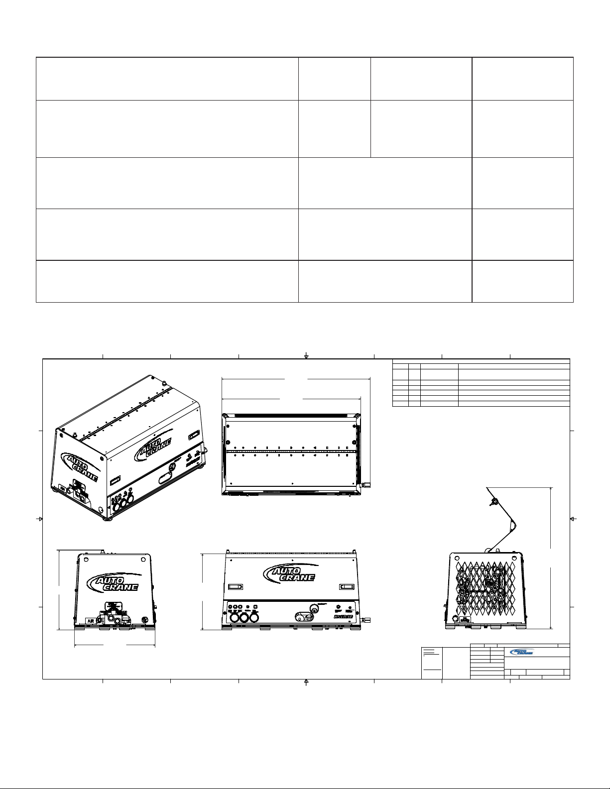
34 3/4 in
[883.0 mm]
3 7 1/ 8 i n
[944.2 mm]
1 9 1/ 8 in
[484.2 mm]
WITH DOOR
CLOSED
20 1/4 in
[514.4 mm]
20 in
[506.8 mm]
35 1/4 in
[895.9 mm]
WITH DOOR
OPEN

7
WARNING
AIR COMPRESSOR SAFETY PRECAUTIONS
Safety is basically common sense. While there are standard safety rules, each situation has its own
peculiarities that cannot always be covered by rules. Therefore with your experience and common
sense, you are in a position to ensure your safety. Lack of attention to safety can result in:
accidents, personal injury, reduction of efficiency and worst of all - Loss of Life. Watch for safety
hazards. Correct them promptly. Use the following safety precautions as a general guide to safe
operation:
Do not attempt to remove any compressor parts without first relieving the entire system of
pressure.
Do not attempt to service any part while machine is operating.
DANGER
Do not operate the compressor at pressure(s) or speed in excess of its rating as indicated in
“Compressor Specifications”.
Periodically check all safety devices for proper operation.
Do not play with compressed air. Pressurized air can cause serious injury to personnel.
Exercise cleanliness during maintenance and when making repairs by covering parts and exposed
openings.
SAFETY
ALLUNITSARE SHIPPEDWITHADETAILEDOPERATORSANDPARTS
MANUAL. THISMANUALCONTAINSVITALINFORMATIONFORTHESAFE
USEANDEFFICIENTOPERATIONOFTHIS UNIT. CAREFULLYREAD
THEOPERATORSMANUALBEFORE STARTINGTHE UNIT. FAILURE TO
ADHERE TO THE INSTRUCTIONS COULD RESULT IN SERIOUS BODILY
INJURYORPROPERTYDAMAGE.
CHECKTHECOMPRESSORSUMPOILLEVELONLYWHENTHECOMPRESSOR
ISNOTOPERATINGANDSYSTEMISCOMPLETELYRELIEVEDOFPRESSURE.
OPENSERVICEVALVETOENSURERELIEFOFSYSTEMAIRPRESSUREWHEN
PERFORMINGMAINTENANCEONCOMPRESSORAIR/OILSYSTEM. FAILURE
TOCOMPLYWITHTHISWARNINGMAYCAUSEDAMAGETOPROPERTY
AND SERIOUS BODILYHARM.

8
SAFETY
Do not install a shut-off valve between the compressor and compressor oil sump.
DANGER
Do not disconnect or bypass safety circuit system.
Do not install safety devices other than authorizedAUTO CRANE replacement devices.
Close all openings and replace all covers and guards before operating compressor unit.
Tools, rags, or loose parts must not be left on the compressor or drive parts.
Do not use flammable solvents for cleaning parts. This can cause the unit to ignite during operation.
Keep combustibles out of and away from the Compressor/Inlet and any associated enclosures.
The owner, lessor, or operator of the Compressor are hereby notified and forewarned that any
failure to observe these safety precautions may result in damage or injury.
AUTO CRANE expressly disclaims responsibility or liability for any injury or damage caused by
failure to observe these specified precautions or by failure to exercise that ordinary caution and
due care required when operating or handling the Compressor, even though not expressly specified
above.
DONOTUSEAUTOCRANECOMPRESSORSYSTEMSTOPROVIDEBREATHING
AIR. SUCH USAGE, WHETHER SUPPLIED IMMEDIATELY FROM THE
COMPRESSOR SOURCE, OR SUPPLIED TO BREATHING TANKS FOR
SUBSEQUENTUSE,CAN CAUSESERIOUS BODILYINJURY.
AUTOCRANEDISCLAIMSANYANDALLLIABILITIESFORDAMAGEFORLOSS
DUE TO PERSONAL INJURIES, INCLUDING DEATH, AND/OR PROPERTY
DAMAGE INCLUDING CONSEQUENTIAL DAMAGES ARISING OUT OF ANY
AUTOCRANECOMPRESSORS USEDTOSUPPLYBREATHINGAIR.

9
SAFETY
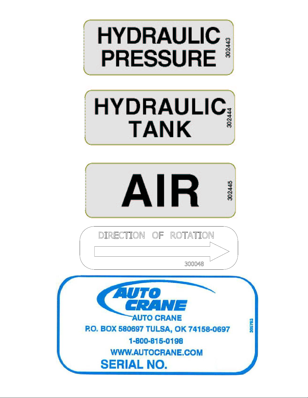
A compliment of warning decals is supplied with each unit. These decals must be affixed to the
comressor package in the locations noted in this manual. If for any reason a safety decal is
removed it is the owners responsibility to make sure it is replaced.
10
11
304174

12
COMPRESSOR TERMINOLOGY
AIR/OILCOALESCER- Performs second stage separation of oil from compressed air feeding
air tools. Sometimes referred to as the separator element.
CFM - Refers to the volume of compressed air being produced, expressed as cubic feet of air per
minute.
COMPRESSOR LUBRICANT - DEXRON IIIATF.
GPM- Refers to the amount of gallons per minute of hydraulic fluid flowing through the pump.
OILSUMP - The first stage of oil separation from compressed air. Also serves as reservoir area
for compressor lubricant and sometimes referred to as the receiver tank.
PSI - Refers to the operating pressure the system is set up at, expressed as pounds per square
inch.
SAFETYVALVE-Avalve located on the oil sump which opens in case of excessive pressure.
Sometimes referred to as the pop-off or pressure relief valve.

13
DESCRIPTION OF COMPONENTS
COMPRESSORASSEMBLY
TheAUTO CRANE hydraulic drive compressor assembly is a positive displacement, oil flooded,
rotary screw type unit employing one stage of compression to achieve the desired pressure.
Components include a housing (stator), two screws (rotors), bearings, and bearing supports.
Power from the hydraulic motor shaft is transferred to the male rotor through a drive coupling.
The female rotor is driven by the male rotor. There are five lobes on the male rotor while the
female rotor has six roots.
PRINCIPLES OF OPERATION
In operation, two helical grooved rotors mesh to compress air. Inlet air is trapped as the male
lobes roll down the female grooves, pushing trapped air along, compressing it until it reaches the
discharge port in the end of the stator and delivers smooth-flowing, pulse-free air to the receiver.
During the compression cycle, oil is injected into the compressor and serves these purposes:
1. Lubricates the rotating parts and bearings.
2. Serves as a cooling agent for the compressed air.
3. Seals the running clearances.
LUBRICATION SYSTEM
Oil from the compressor at discharge pressure, is directed into it’s integral housing, through the
thermal valve and filter, and then out of the integral housing to the oil cooling system, and then back
to the side of the compressor stator, where it is injected into the compressor. At the same time oil
is directed internally to the bearings and shaft seal of the compressor.
OIL SUMP
Compressed, oil-laden air enters the sump from the compressor. As the oil-laden air enters the
sump, most of the oil is separated from the air as it passes through a series of baffles and de-fusion
plates. The oil accumulates at the bottom of the sump for recirculation. However, some small
droplets of oil remain suspended in the air and are passed on to the Coalescer.

14
DESCRIPTION OF COMPONENTS
SAFETYVALVE
The pop safety valve is set at 200 PSI and is located at the top of the air/oil sump. This valve acts
as a backup to protect the system from excessive pressure that might result from a malfunction.
AIR/OIL COALESCER
The coalescer is self-contained within a spin-on housing. When air is demanded at the service line,
it passes through the coalescer which efficiently provides the final stage of oil separation.
OIL RETURN LINE
The oil that is removed by the coalescer accumulates and is returned through an internal oil return
line leading to the compressor.
MINIMUM PRESSUREVALVE
The minimum pressure valve is located at the outlet of the coalescer head and serves to maintain a
minimum discharge pressure of 75 PSIG in operation, which is required to assure adequate
compressor lubrication pressure.
OILFILTER
The compressor oil filter is a removable and cleanable screen built into the side of the compressor
housing. Screen replacement may be necessary after several cleanings.
COMPRESSOR OILAND HYDRAULIC OIL COOLING SYSTEMS
The compressor cooling system consists of a combination hydraulic cooler and compressor cooler
mounted on the common frame. Compressor oil temperature is controlled by a thermal valve
located down stream of the oil filter. The thermal valve maintains the compressor oil temperature
at 185ºF. Cool air is drawn through the vented end panel and across the combo cooler. The air is
heated by the coolers and the hot air exits out the back vented panel . Allow for adequate
clearance (12”) for the air to exit. Also, the package location should not be subjected to above
ambient air temperatures.

15
DESCRIPTION OF COMPONENTS
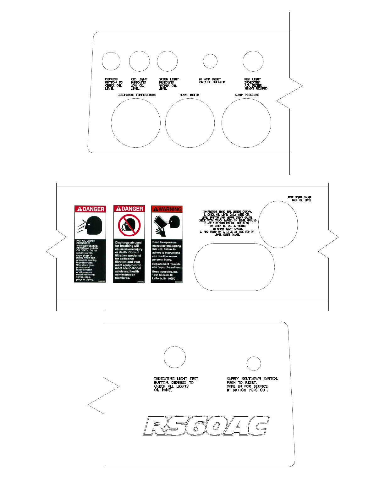
INSTRUMENTATION
TheAUTOCRANEhydraulic drive compressor unit incorporates agaugepanelthatmonitors
temperature,pressureand hours ofoperation.
HOURMETER
Thehourmeterrecordsthetotal number of operatinghours. Itservesasa guide in followingthe
recommendedinspectionandmaintenance schedule. The hourmeter willonlyrunwhenthereispressure
inthesystem.
COMPRESSORDISCHARGEAIR/OILTEMPERATURE SWICHGAUGE
Thisswichgaugeindicatescompressorair discharge temperature. The swichgauge ensuressafety
shutdownincaseofexcessiveoperatingtemperatures,preventingcompressordamage,bystopping
hydraulicflowtothecompressormotor.
ELECTRICALANDSAFETYSYSTEM
TheAUTO CRANE compressor’sstandardelectricalsystemconsists of:
-Gaugepanelwithatemperatureswichgauge,hourmeteranddischargepressureswichgauge.
-Compressorandhydraulicoilcoolerfanassemblyand relay.
-Compressoraftercooler/oilcoolerfanassemblywithrelay.
-N.O.hourmeterpressure switch.
-N.C.blowdown pressure switch.
-12VDCN.O.hydraulic solenoid andrelay.
-Switchrelayforcustomerequipmentinterfaceduringcompressor operation.

16
DESCRIPTION OF COMPONENTS
AUTOMATIC BLOW DOWN VALVE
There is one blow down valve in the compressor system. It is located at the intake valve and will
automatically bleed the sump to zero pressure when the compressor is disengaged. Blow down
time interval takes between 45 and 60 seconds.
CONTROL SYSTEM
The prime component of the compressor control system is the compressor inlet valve. The control
system is designed to match air supply to air demand and to prevent excessive discharge pressure
when compressor is at idle. Control of air delivery is accomplished by the inlet valve regulation
and modulation as directed by the discharge pressure regulator.
NORMALYOPEN REGULATOR SOLENOID
A closed Furnas air pressure switch will energize the normaly open regulator solenoid, thus closing
it. When the normaly open regulator solenoid is closed, air pressure will rise. When it is open air
pressure falls only in the compressor sump.
Note: See page 28 for description of Furnas switch.
NOTE: Most air tools operating pressure range is between 90 and 125 psi. Operating
above the tools recommended pressures will decrease the life of the tool. Higher
operating pressure can also over torque nut and bolts fatiguing the fastener and mating
parts. Strictly adhere to tool operating pressures and torque standards set forth by the
tool manufacturer and the specifications of the equipment that work is being performed
on.
INLETVALVE
The compressor inlet valve is a piston operated disc valve that regulates the inlet opening to control
capacity and serving as a check valve at shutdown.

17
INSPECTION, LUBRICATION, AND MAINTENANCE
Thissection contains instructions for performing the inspection,lubrication, and maintenance
procedures required to maintain the compressor in proper operating condition. The importance of
performing the maintenance described herein cannot be over emphasized.
The periodic maintenance procedures to be performed on the equipment covered by this manual
are listed below. It should be understood that the intervals between inspections specified are
maximum interval. More frequent inspections should be made if the unit is operating in a dusty
environment, in high ambient temperature, or in other unusual conditions. Aplanned program of
periodic inspection and maintenance will help avoided premature failure and costly repairs. Daily
visual inspections should become a routine.
The LUBRICATIONAND MAINTENANCE CHART lists serviceable items on this compressor
package. The items are listed according to their frequency of maintenance, followed by those
items which need only “As Required” maintenance.
The maintenance time intervals are expressed in hours. The hourmeter shows the
total number of hours your compressor has run. Use the hourmeter readings for determining your
maintenance schedules. Perform the maintenance at multiple intervals of the hours shown. For
example, when the hourmeter shows “100” on the dial, all items listed under “EVERY10 HOURS”
should be serviced for the tenth time, and all items under “EVERY 50 HOURS” should be
serviced for the second time, and so on.
DANGER
COMPRESSOR MUST BE SHUT DOWN AND COMPLETELY RELIEVED OF
PRESSUREPRIORTO CHECKINGFLUID LEVELS. OPEN SERVICEVALVETO
ENSURERELIEFOFSYSTEMAIRPRESSURE. FAILURETOCOMPLYWITHTHIS
WARNINGMAYCAUSEDAMAGETOPROPERTYANDSERIOUSBODILYHARM.

18
LUBRICATION AND MAINTENANCE CHART
NOTE: Compressor oil and filter is to be changed after the first 50 hours of operation. After this,
normal intervals are to be followed.
LAVRETNINOITCA
YLLACIDOIREP GNIRUD NOITAREPO
egnahcynaetoN.gnidaereguagllaevresbO.1 ehtenimreteddnagnidaerlamronehtmorf :ETON(.edamsriaperyrassecenevaH.esuac nehwgnidaereguaglausuehtsi"LAMRON" yadotyadanosnoitidnocralimistagnitarepo ).noitarepo
YLIAD
.levelliorosserpmocehtkcehC.1 rotacidniporderusserP.retlifriakcehC.2 .gnitareposirosserpmocelihw .skaelriadnaliorofkcehC.3 .sehctiwstiucricytefaskcehC.4
SRUOH52YREVE YLHTNOMRO .liorosserpmocmorfretawniarD.1
005YREVE 6ROSRUOH SHTNOM
neercsecalperdnaliorosserpmocegnahC.1 .egakaelroflaestfahsrosserpmockcehC.2 .spmalcdnasgnittif,gnipipretlifriakcehC.3 .stroppusrosserpmockcehC.4 retrohS(.tnemeleretlifriawenllatsnI.5 ytsudrednuyrassecenebyamlavretni ).snoitidnoc .evlavytefaspmuskcehC.6
0001YREVE 1ROSRUOH RAEY .tnemelegnicselaocegnahC.1
ROYLLACIDOIREP DERIUQERSA
.tnemeleretlifrianaelcdnatcepsnI.1 recselaocno-nipsecalperdnatcepsnI.2 .yrassecenfitnemele .snifrelooclionaelcdnatcepsnI.3

19
LUBRICANT RECOMMENDATIONS
WARNING
The following are general characteristics for a rotary screw lubricant. Due to the impossibility of
establishinglimits on all physical and chemical propertiesof lubricants which can affect their
performance in the compressor over a broad range of environmental influences, the responsibility
forrecommending and consistently furnishing a suitable heavyduty lubricant must rest with the
individual supplier if they choose not to use the recommendedAUTO CRANE rotary screw
lubricant. The lubricant supplier’s recommendation must, therefore, be based upon not only the
following general characteristics, but also upon his own knowledge of the suitability of the
recommended lubricant in helical screw type air compressors operating in the particular
environmentinvolved.
CAUTION
IT IS IMPORTANT THAT THE COMPRESSOR OIL BE OF A RECOMMENDED
TYPE AND THAT THIS OILAS WELL AS THE AIR FILTER, OIL FILTER, AND
COALESCERELEMENTSBEINSPECTEDAND REPLACEDASSTATED INTHIS
MANUAL.
THE COMBINATION OFACOALESCER ELEMENT LOADED WITH DIRTAND
OXIDIZEDOILPRODUCTSTOGETHERWITHINCREASEDAIRVELOCITYASA
RESULT OFTHISCLOGGEDCONDITION MAYPRODUCEACRITICALPOINT
WHILETHEMACHINEISINOPERATIONWHEREIGNITIONCANTAKEPLACE
ANDCOULD CAUSEAFIRE INTHEOILSUMP.
FAILURE TO COMPLY WITH THIS WARNING MAY CAUSE DAMAGE TO
PROPERTYAND SERIOUSBODILYHARM.
MIXING DIFFERENT TYPES OR BRANDS OF LUBRICANTS IS NOT
RECOMMENDED DUE TO THE POSSIBILITY OF A DILUTION OF THE
ADDITIVESORAREACTIONBETWEENADDITIVES OFDIFFERENTTYPES.

20
LUBRICANT RECOMMENDATIONS
LUBRICANT CHARACTERISTICS
1. Flashpoint 400°F minimum.
2. Pour point -40°F.
3. Contains rust and corrosion inhibitors.
4. Contains foam suppressors.
5. Containsoxidation stabilizer.
NOTE
NOTE
DUETOENVIRONMENTALFACTORSTHEUSEFULLIFEOFALL“EXTENDED
LIFE”LUBRICANTS MAYBESHORTERTHAN QUOTEDBYTHELUBRICANT
SUPPLIER. AUTOCRANE ENCOURAGESTHE USER TOCLOSELYMONITOR
THE LUBRICANT CONDITION AND TO PARTICIPATE IN AN OIL ANALYSIS
PROGRAMWITHTHESUPPLIER.
NO LUBRICANT, HOWEVER GOOD AND/OR EXPENSIVE, CAN REPLACE
PROPERMAINTENANCEANDATTENTION. SELECTAND USE ITWISELY.

21
MAINTENANCE
If some of the maintenance intervals in the schedule outlined in this manual seem to be rather short,
it should be considered that one hour’s operation of a compressor is equal to about 40 road miles
on an engine. Thus, eight hours operation is equal to 320 road miles, 250 hours is equal to 10,000
road miles, etc.
COMPRESSOR OILSUMPFILL, LEVEL,AND DRAIN
Before adding or changing compressor oil make sure that the compressor is completely relieved of
pressure. Oil is added at the fill cap on the side of the compressor body. Adrain valve/hose
assembly is provided at the bottom of the compressor body. The proper oil level, when unit is shut
down and has had time to settle between the top and the midpoint of the upper oil sightglass. The
truck must be level when checking the oil. DO NOT OVERFILL. The oil sump capacity is given
in“Compressor Specifications”. DANGER
AIR INTAKE FILTER
The air intake filter is a heavy-duty dry type high efficiency filter designed to protect the
compressor from dust and foreign objects. Optional two-stage available.
Optional filter is equipped with an evacuator cup for continuous dust ejection while operating and
when stopped.
Frequency of maintenance of the filter depends on dust conditions at the operating site. The filter
element must be serviced when clogged (maximum pressure drop for proper operation is 15”
of water). The filter is equipped with a pressure drop indicator, and the element should be
changed based on it’s reading first and then by the maintenance intervals outlined.
DO NOTATTEMPTTO DRAIN CONDENSATE, REMOVETHE OILLEVELFILL
PLUG, OR BREAKANYCONNECTIONINTHEAIROR OILSYSTEMWITHOUT
SHUTTINGOFFCOMPRESSORANDMANUALLYRELIEVINGPRESSUREFROM
THESUMP. FAILURETOCOMPLYWITHTHISWARNINGMAYCAUSEDAMAGE
TOPROPERTYANDSERIOUS BODILYHARM.

22
MAINTENANCE
AIR/OIL COALESCER
The air/oil coalescer employs an element permanently housed within a spin-on canister. This is a
single piece unit that requires replacement when it fails to remove the oil from the discharge air, or
pressure drop across it exceeds 15 PSI. Dirty oil clogs the element and increases the pressure
drop across it.
To replace element proceed as follows:
1. Shutdown compressor and wait for complete blow down (zero pressure).
2. Turn element counterclockwise for removal (viewing element from bottom).
3. Apply a film of fluid directly to seal on the new element.
4. Rotate element clockwise by hand until element contacts seal (viewing element from
bottom).
5. Rotate element approximately one more turn clockwise with band wrench near the top
ofelement.
6. Run system and check for leaks.
WARNING
COALERSCER OIL RETURN
This originates at the bottom of the air/oil coalescer and flows through a special recovery
pipe and venturi nozzle. If the coalerscer starts to fill with oil there is a good chance the
venturi or pipe has been plugged. Consult factory for cleaning instructions.
DO NOT SUBSTITUTE ELEMENT. USE ONLY A GENUINE AUTO CRANE
REPLACEMENT ELEMENT. THIS ELEMENT IS RATEDAT 200 PSI WORKING
PRESSURE. USEOFANYOTHERELEMENTMAYBEHAZARDOUSANDCOULD
IMPAIR THE PERFORMANCE AND RELIABILITY OF THE COMPRESSOR,
POSSIBLY VOIDING THE WARRANTY AND/OR RESULTING IN DAMAGE TO
PROPERTYAND SERIOUSBODILYHARM.

23
MAINTENANCE
OILFILTER
The compressor oil filter is a throwaway type cartridge. It is designed with a built-in bypass so that
if there is a large restriction, due to cold oil or clogged element, the compressor will still be
lubricated.
To replace filter proceed as follows:
1. Make sure system pressure is relieved.
2. Unscrew with 14mm allen wrench.
3. Remove oil filter from housing.
4. Replace the oil filter screen element.
5. Reinsertoil filter screen into housingand tighten with 14mm allen wrench.
6. Add oil (total system takes one gallon), re-tighten filler cap.
7. Check for leaks in operation.
WARNING
HYDRAULIC OILCOOLERAND COMPRESSOR OILCOOLER COMBINATION
The interior of the oil cooler should be cleaned when the pressure drop across it at full flow
exceeds 25 PSI. The following procedure has been recommended by the vendor who supplies the
cooler:
1. Remove cooler.
2. Circulate a suitable solvent to dissolve and remove varnish and sludge.
3. Flush generously with compressor lubricant (compressor oil cooler section only, use
hydraulic oil to flush the hydraulic cooler portion on the combo cooler).
4. Once the coolers are reinstalled, fill the compressor and hydraulic systems with the
proper fluids to their appropriate levels.
DO NOT SUBSTITUTE ELEMENT. USE ONLY A GENUINE AUTO CRANE
REPLACEMENT ELEMENT. USE OF ANY OTHER ELEMENT MAY BE
HAZARDOUSAND COULD IMPAIR THE PERFORMANCEAND RELIABILITY
OF THE COMPRESSOR, POSSIBLY VOIDING THE WARRANTY AND/OR
RESULTINGIN DAMAGETOPROPERTYANDSERIOUS BODILYHARM.
This manual suits for next models
1
Table of contents
Other Auto Crane Air Compressor manuals


Popular Air Compressor manuals by other brands


Craftsman
Craftsman 919.165180 owner's manual

Oshkosh Corporation
Oshkosh Corporation IMT CAS80R Installation, Operation, Maintenance & Parts Manual

Clarke
Clarke RANGER 24 Operation & maintenance instructions

Husky
Husky 41004 Operator's manual

Sullair
Sullair TS32 Series user manual

Vmac
Vmac H400005 Installation and owner's manual


