CruzPro PR60 User manual

Page 3
Digital Pressure Gauge/Alarm
CruzPro
PR60
Page 14
Other CruzPro Products
lDepthsounders & Speed/Temperature/Log
lDC Volts/Amps/Amp-Hour Monitor
lAC Volts/Amps//Freq/kW Monitor
lLPG/Petrol Gas Detectors/Alarms
lBilge Water Alarms & Bilge Pump Controllers
lWindlass Controller/Chain Counter
lDigital Fuel Gauges & Fuel Consumption Calculator
lDigital Gauges for 1 & 3 Tanks /w Separate Alarms
lSmart and Manual Alternator Regulators
lMarine Security System
lRPM/Engine Hours/Elapsed Time Gauge
lDigital Oil Pressure Gauge/Alarm
lDigital Water Temperature Gauge/Alarm
lOne and Three Bank Digital Volts Gauges
lDigital Amps Gauge
lDigital Clock/Watch/Race Timers/Alarms
l8 and 16 Amp Light Dimmers / Motor Speed Controller
lSolar Panel Charge Controllers 6/8/9 & 20 Amps
l4 & 8 Channel NMEA Combiners/RS-232 Convertors
lEngine/Exhaust Temp. Monitor & Digital Pyrometer
lRemote Digital NMEA 0183 Data Repeater
Introduction
ThePR60DigitalPressureGaugeprovidesanaccurate
display of pressure. Pressure can be displayed up to
6550 units (PSI or Bars) or as a percentage (0 to
100%). ThePR60 is pre-programmedfor use withall
popular American and European resistive pressure
senders made by VDO, Teleflex, Mercury, GM,
Stewart-Warner, Centroid, Faria and others. Custom
0-5Vand4-20mAversionsarealsoavailableby special
order. Low and High level alarms can be set over the
entirerangeoftheinstrument/sender. When activated,
thebuilt-in 85 dB alarmwillsound and the displaywill
flash. Fivelevels of backlightingcanbeselectedand all
set-up, alarm values, sender type and maximum tank
capacity are saved in a non-volatile memory. The
PR60outputsNMEA0183serialdataorthis output pin
can be programmed to activate an external alarm.
Notes

Page 4
Table of Contents
Introduction . . . . . . . . . . . . . . . . . . . . . . . . . . . . 3
Specifications . . . . . . . . . . . . . . . . . . . . . . . . . . . 4
Installation . . . . . . . . . . . . . . . . . . . . . . . . . . . . . .5
Mounting and Wiring. . . . . . . . . . . . . . . . . . . . . . . 6
Operation . . . . . . . . . . . . . . . . . . . . . . . . . . . . . . .8
Key Functions . . . . . . . . . . . . . . . . . . . . . . . . . . . . 8
Backlight Intensity . . . . . . . . . . . . . . . . . . . . . . . . . 8
Setting Low/High Level Alarms . . . . . . . . . . . . . . . 9
Alarms On/Off . . . . . . . . . . . . . . . . . . . . . . . . . . . 9
Displaying Pressure . . . . . . . . . . . . . . . . . . . . 10
Selecting Sender Type . . . . . . . . . . . . . . . . . . . . 11
Setting Maximum Tank Capacity . . . . . . . . . . . . . . . . 12
Selecting NMEA 0183 or External Alarm Output . . . . .13
Other CruzPro Products . . . . . . . . . . . . . . . . . . . 16
Specifications
Power supply: 9.5 to 33.0 VDC, .035 amps nom.
Operating temperature: 32 to 122 F ( 0 to 50 C)
Size: 2.5" dia X 4.1" deep (61mm x 104 mm)
Accuracy: Limited only by sender accuracy
Senders: Works with 0-30, 0-70, 0-90, 10-73, 10-
180, 33-240, 40-250 ohm resistive senders by VDO,
Teleflex, GM, Stewart-Warner, Mercury, Faria, and
others (both American and European styles). Custom
versions available for 0-5V and 4-20mA senders.
Alarms: 85 db internal Low and High level alarms,
settable from 000.0 to 6553. External alarm output.
Display: 4 digits, PSI, Bars or %, 000.0 to 6553. Five
levelsofbacklighting.
Data output: NMEA 0183 4800 baud serial output
of pressure. $IIXDR sentence or programmable as an
externalalarm output.
Page 15
2016 BV Engineering PR60MAN-A
http://www.cruzpro.com [email protected]
Page 13
Notes
Selecting NMEA 0183 or External Alarm Output
To toggle Screw Terminal Pin (C) between NMEA
0183 and External Alarm Output, press and hold
down both the tand s keys for 10 seconds (until
you hear a long beep). The new output mode is
automatically saved to memory. When the external
alarm output is activated, a 5V signal (10 mA Max.)
is output on screw terminal (C).
Page 5
Page 7
Page 10
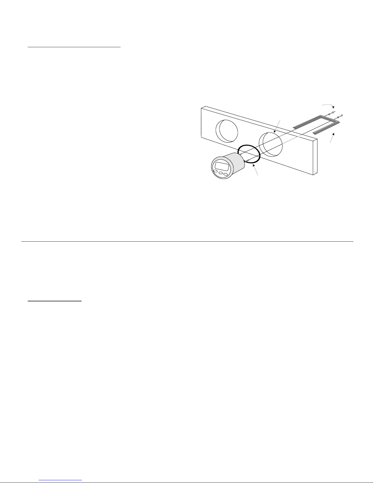
Figure 1
Installation
Before starting the installation, please read this
entire section first. Be sure to install the bulkhead
gasket before you install the instrument. Finger
tighten the screws that mount the instrument bracket
- do not use tools.
Page 12
driver to make the connections to the screw terminal
on the instrument case back as shown in figure 2.
lCarefully check all your wiring against those
shown in figure 2. If everything is wired correctly
youcan mount thePR60 intheinstrumenthole. Be sure
the bulkhead gasket is in place and use only finger
tension to tighten the bracket hold-down nuts Do not
overtighten the bracket or you may damage the case
- do not use tools to tighten the nuts.
DisplayingPressure
Press the :key to display pressure (PSI or Bars).
Press the skey to display pressure in percent (0 to
100%).
SettingMaximum Pressure Range
Press and hold down the :key for 10 seconds (until
you hear a long beep.) Use the t and skeys to set
themaximumpressureforyourpressuresender, either
inPSIorBars.Oncethemaximumpressureisshowing
on the display, press the :key for 1/2 second to save
thisvalue intomemory.
Bulkhead
Gasket
2-1/8" (55mm) hole
Mounting
Bracket
Finger tighten only - Do not use tools

Page 11
Page 6
Mounting and Wiring
lDrill a 2-1/8" (55mm) mounting hole where you
desire to mount the instrument (Figure 1).
lBring the sender wires, ground, and power lines
out of the mounting hole and use a small flat screw-
Figure 2
Page 9
Figure 1
Page 8
Operation
Key Functions
The keys are used to select
backlightlevels, displaypressure(PSI,Barsor percent),
setthe low/high level alarms,selectsender type and set
themaximum senderpressure. Afterchangesare made,
thenewinformationisautomaticallysavedtomemory.
Backlight Intensity
Press the key for 1/2 second to adjust the
backlight level for night-time viewing. Each time
you press the "+" key for 1/2 second, the backlight
level will change: 1, 2, 3, 4, OFF, 1, 2, ... etc.
Setting Low/High Level Alarms
Whileviewing pressure, press andhold the tor skey
for ten (10) seconds to view/set the Low or High
pressure alarms. You will hear a long beep and the
alarmvalue is displayed. Pressthe sand tkeys toset
the desired alarm limit (000.0 to 6553 PSI or Bars).
Pressthe"+"keyfor 1/2 second to save your entry to the
non-volatilememory.
Alarms ON/Off
Press the sor tkey for 1/2 second to "arm" or
"disarm" the level alarms. The display will flash
"On" or "OFF" briefly to show you the state of the
alarms. You should leave the alarms armed at all
times and only disarm it to silence the alarm buzzer.
Selecting Sender Type
Press and hold down both the tand "+" keys for 10
seconds (until you hear a long beep.) Use the sand
t keys to select the correct sender from the list
below. Once the correct sender has been chosen,
press the "+" key for 1/2 second to save your entry.
U- 1 0-30 Ohm
U- 2 0-70 Ohm
U- 3 0-90 Ohm
U- 4 10-73 Ohm
U- 5 10-180 Ohm
U- 6 33-240 Ohm
U- 7 40-250 Ohm
U- 8 30-0 Ohm
U- 9 70-0 Ohm
U-10 90-0 Ohm
U-11 73-10 Ohm
U-12 180-10 Ohm
U-13 240-33 Ohm
U-14 250-40 Ohm
U-15 0-5 Volts
U-16 5-0 Volts
U-17 4-20 mA


