Auto Crane AC30A User manual

AC30A
COMPRESSOR
OWNERS MANUAL
Rev. 03/15/2011
Serial No. __________________
Mailing Address:
P.O. Box 580697
Tulsa, OK 74158-0697
Physical Address:
4707 N. Mingo Rd.
Tulsa, OK 74117-5904 Phone (918) 836-0463
Manual No. AC30A Fax (918) 834-5979
Rev. 07/08/2008 http://www.autocrane.com

To: Fax:
From: Date:
Re: Pages:
Name: Phone:
Address:
City: State: Zip:
Contact:
Name:
Address:
City: State: Zip:
Contact:
VIN #
ONE REGISTRATION FORM PER UNIT (CRANE OR BODY)
Registration form must be mailed or faxed within 15 days of customer installation.
Mail to:
Warranty Department
Auto Crane Company
P.O. Box 581510
Tulsa, OK 74158-0697
Date Product Delivered: Date Processed:*
* For Auto Crane use only
Product Information:
(Required for Warranty Activation)
Model No.: Serial No.:
E-mail Address:
Distributor Information:
(Required for Warranty Activation)
Product Registration
E-mail Address:
(Required for Warranty Activation)
Auto Crane Warranty Registration
(918) 834-5979Warranty Department
End User Information:
Fax Transmission
Warranty Registration Rev. 050905

10/09
Rev Date Section(s)OrPage(s) Description of Change
09/02/03 Last page New 2-year warranty policy to replace 1-year warranty
policy
05/09/05 2nd Quarter New Revisions
11/28/05 3-1.0.0 Updated for new hydraulic motor
06/10/06 Updated for new machine design.
07/12/07 Bill of Materials Audit
08/13/07 Updated Drawing
11/28/11 Updated Drawing 200280-999
AC30A
OWNER’S MANUAL – REVISION RECORD

10/09
WARNINGS
READ THIS PAGE
WARNING! Federal law (49 cfr part 571) requires that the Final Stage Manufacturer of a vehicle
certify that the vehicle complies with all applicable federal regulations. Any modifications performed
on the vehicle prior to the final state are also considered intermediate stage manufacturing and must
be certified as to compliance. The installer of this crane and body is considered on of the
manufacturers of the vehicle. As such a manufacturer, the installer is responsible for compliance
with all applicable federal and state regulations, and is required to certify that the vehicle is in
compliance.
WARNING! It is the further responsibility of the installer to comply with the OSHA Truck Crane
Stability Requirements as specified by 29 CFR part 1910.180 (C) (1).
WARNING! NEVER OPERATE THE CRANE NEAR ELECTRICAL POWER LINES!
Death or serious injury will result from boom, line, or load contacting electric lines. Do not use crane
within 10 feet (3.05m) of electric power lines carrying up to 50,000 volts. One foot additional
clearance is required for every additional 30,000 volts or less. SEE DANGER DECAL (P/N 040529)
in this Owner's Manual.
WARNING! NEVER.........................................
i EXCEED load chart capacities (centerline of rotation to hoist hook).
i Un-reel last 5 wraps of cable from drum!
i Wrap cable around load!
i Attempt to lift or drag a load from the side! The boom can fail far below its rated capacity.
i Weld, modify, or use unauthorized components on any Auto Crane unit! This will void any
warranty or liability. Also failure of the crane may result.
i Place a chain link on the tip of the hook and try to lift a load!
i Use a sling bar or anything larger than the hook throat that could prevent the hook latch from
closing, thus negating the safety feature!
i Hold on any pendant Select Switch that will cause unsafe operating conditions!
WARNING! In using a hook with latch, ALWAYS make sure that the hook throat is closed before
lifting a load! Proper attention and common sense applied to the use of the hoist hook and various
slings will prevent possible damage to material being hoisted and may prevent injury to personnel.
WARNING! Failure to correctly plumb and wire crane can cause inadvertent operation and damage
to crane and/or personnel!
WARNING! Auto Crane Company remote controlled cranes are not designed or intended to be
used for any applications involving the lifting or moving of personnel.
WARNING! ALWAYS operate the crane in compliance with the load capacity chart. DO NOT USE
the overload shutdown device to determine maximum rated loads, if the crane is equipped with this
type of device.

10/09
SPECIFICATIONS.............................................................................. 1-1.0.0
GENERAL DIMENSIONS................................................................... 1-2.0.0
INSTALLATION INSTRUCTIONS....................................................... 1-3.0.0
OPERATION....................................................................................... 1-4.0.0
SPARE PARTS LIST........................................................................... 1-6.0.0
HYDRAULIC INSTALLATION............................................................. 2-1.0.0
PNEUMATIC SCHEMATIC................................................................. 2-2.0.0
ELECTICAL SYSTEM......................................................................... 2-3.0.0
HYDRAULIC SCHEMATIC.................................................................. 2-4.0.0
GENERAL ASSEMBLY........................................................................ 3-1.0.0
MAINTENANCE.................................................................................. 4-1.0.0
TROUBLESHOOTING......................................................................... 4-2.0.0
RECEIVER TANK................................................................................ 5-1.0.0
FILTER/REGULATOR/LUBRICATOR..................................................6-1.1.0
MISC....................................................................................................7-1.0.0
WARRANTY............................................................................................ LAST PAGE
AC30A HYDRAULIC AIR COMPRESSOR
OWNER’S MANUAL
TABLE OF CONTENTS

10/09
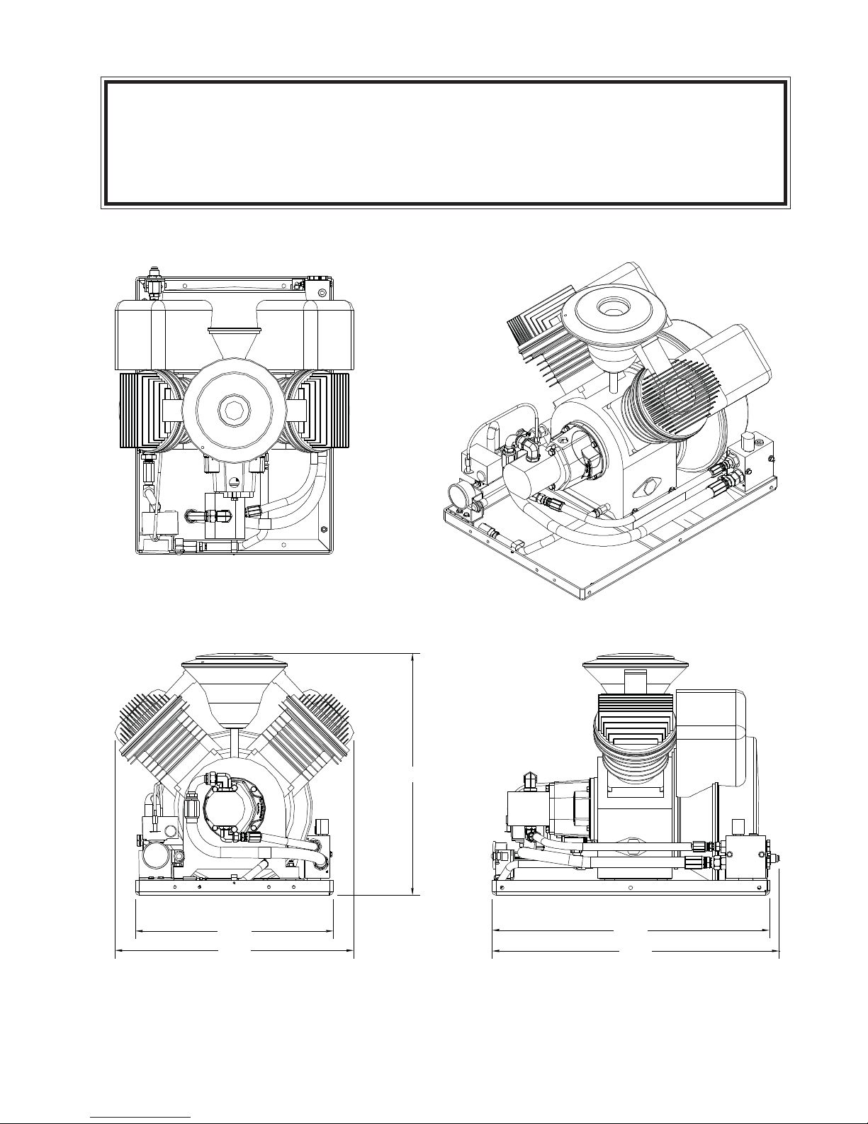
Dimensions
Width: 25.0 in. (AT TOP)
20.0 in. (AT BASE)
Height: 24.5 in.
Length: 28.25 in.
Weight: 250 lbs. w/cage
Performance Data
28.8* cfm (Free Air Cubic Feet per Minute) @
100 psig air outlet pressure and 1800
rpm.
Piston Displacement: 48.5 cfm
*Reference Conditions:
Absolute Inlet Pressure: 14.5 psi
Relative Air Humidity:0 %
Air Inlet Temperature:68° F.
Hydraulic Requirements
Flow (Max): 12 gpm (45.4 l/min)
Pressure: 2500 psi (172 bar)
Fluid Type: Anti-Wear Hydraulic
Fluid viscosity: 150 SSU @ 100°F
Electrical System Requirements
Voltage: 12 Volts DC
Current: 2.5 Amps
Rotation
Bi-rotational Radial Fan Blade
Hose Connections
Pressure: -12 JIC MALE
Return: -12 JIC MALE
Technical Data
Maximum Air Pressure: 145 psig
Nominal RPM: 1800 rpm
Crankcase Oil Capacity: 1.5 qts
Approx. Oil Consumption: .025 oz/hr
Maximum Temperature (@ Outlet): 165°F
Noise Level: 84 dB(A)
1-1.0.0
GENERAL SPECIFICATIONS
AC30A HYD AIR COMPRESSOR
10/09
1-2.0.0
20.00
24.11
24.38
28.00
29.01
GENERAL DIMENSIONS AC30A
10/09
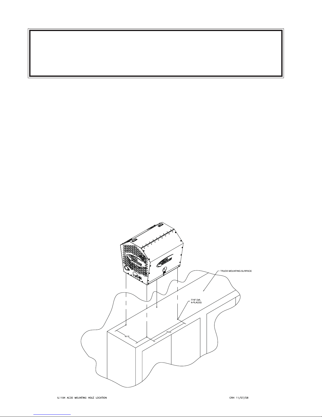
1Locate air pump in a well ventilated
area on truck body.
2Secure to truck body through
bottom side rails using four
(4) 3/8- 24 NF x 2¾ Grade 5 bolts.
Four (4) new 7/16 diameter holes
may be made in the side frame rail
to allow for obstruction problems.
3Remove plastic cap from “T” port in
the hydraulic valve block and install
return line to cooler or reservoir.
4Remove plastic cap from “P” port
in the hydraulic valve block and
install pressure line from hydraulic
pump.
5The mating electrical connector has
4 wires. Red, black and orange. Run
red power wire to a 10 amp fused
switched ignition source. The black
to a frame ground source. The
orange wire is optional and is a
power feed source from the
compressor when the compressor is
running only. This is a 10 amp max.
power feed.
6Attach air hose to the straight 5/8"
fitting (37 degree JIC male) on the
compressor discharge line.
7Follow initial start-up procedure.
1-3.0.0
AC30A
INSTALLATION INSTRUCTIONS

10/09
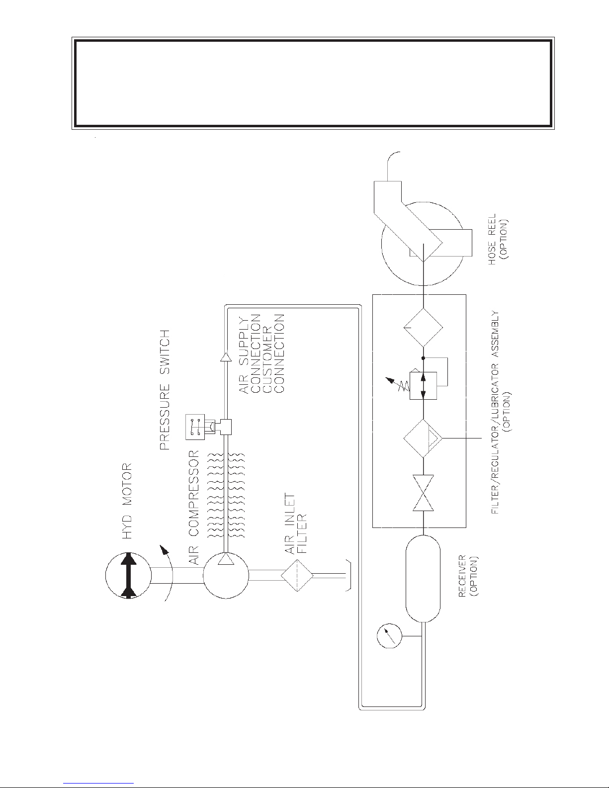
BASIC OPERATION
Air is drawn through the intake filter,
intake manifold and suction discs into
the cylinders. The air is compressed,
then discharged through the delivery
discs to the temperature reducer, where
the heat of the compressed air is partly
removed. From the temperature reducer
the compressed air is discharged
through the 5/8” JIC customer
connection points.
AUTO RUN MODE
When the demand for air is moderate, the
unit should be run in the auto mode.
This allows the compressor to produce
air until the pressure reaches the upper
limit of the pressure switch and stop. At
this point it shuts the compressor off.
When the tank pressure reduces to the
lower limit of the pressure switch the
unit will start up and continue producing
air.
CAUTION: When the hydraulic system
shuts down a shock wave is delivered to
the return line. Locate the hydraulic
coolers and filters a minimum of 10’
away.
The pressure switch is preset to
specified settings.
Pressure Switch:
Shutoff: 150 psig
Restart: 110 psig
1-4.0.0
OPERATION — AC30A

10/09
1Read the AC30A Owner’s Manual.
2Check all wiring for loose
connections.
3Check oil level in sight gauge. It
should be filled to the middle of the
sight glass. If not, fill to the proper
level. Fill with PAO synthetic
lubricant equivalent to Chevron-Gulf
GSL 838A or Summit SH-46. If
petroleum based crankcase oil is
required by operator, use an SAE
10W oil, API classification CD of SF,
Mil Spec MIL-L-2104C or MIL-L-46152.
CAUTION: Do not mix oil types.
4Check that pressure switch operates
at the pressure limits specified.
5Check the oil fill cap on top of
compressor (yellow knob) for
tightness.
6Check hydraulic fluid flow.
CAUTION: More than 12 GPM will
build excess heat in the system.
7Check all piping for leaks.
1-5.0.0
AC30A
INITIAL START-UP PROCEDURE

10/09
1-6.0.0
ITEM QTY PART NO. DESCRIPTION
1 3 750107000 AIR FILTER
2 5 750097000 OIL, CRANKCASE (QT BOTTLES OF PAO OIL)
3 1 302688-012 COIL, HYD VALVE SOLENOID/RELIEF
AC30A RECOMMENDED
SINGLE UNIT SPARE PARTS LIST
10/09
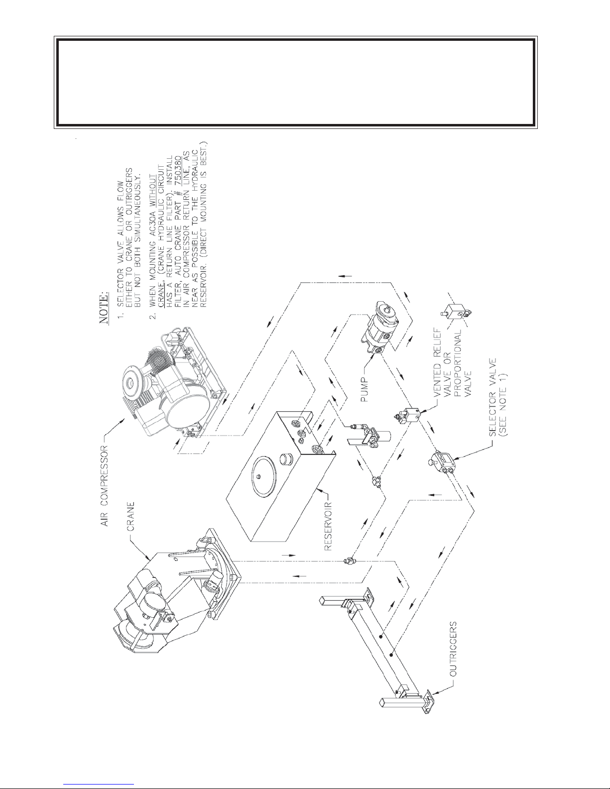
2-1.0.0
TYPICAL AC30A / CRANE
HYDRAULIC INSTALLATION
10/09
2-2.0.0
PNEUMATIC SYSTEM SCHEMATIC

10/09
2-3.0.0
AC30A ELECTRICAL SYSTEM
P/N: 200220-999
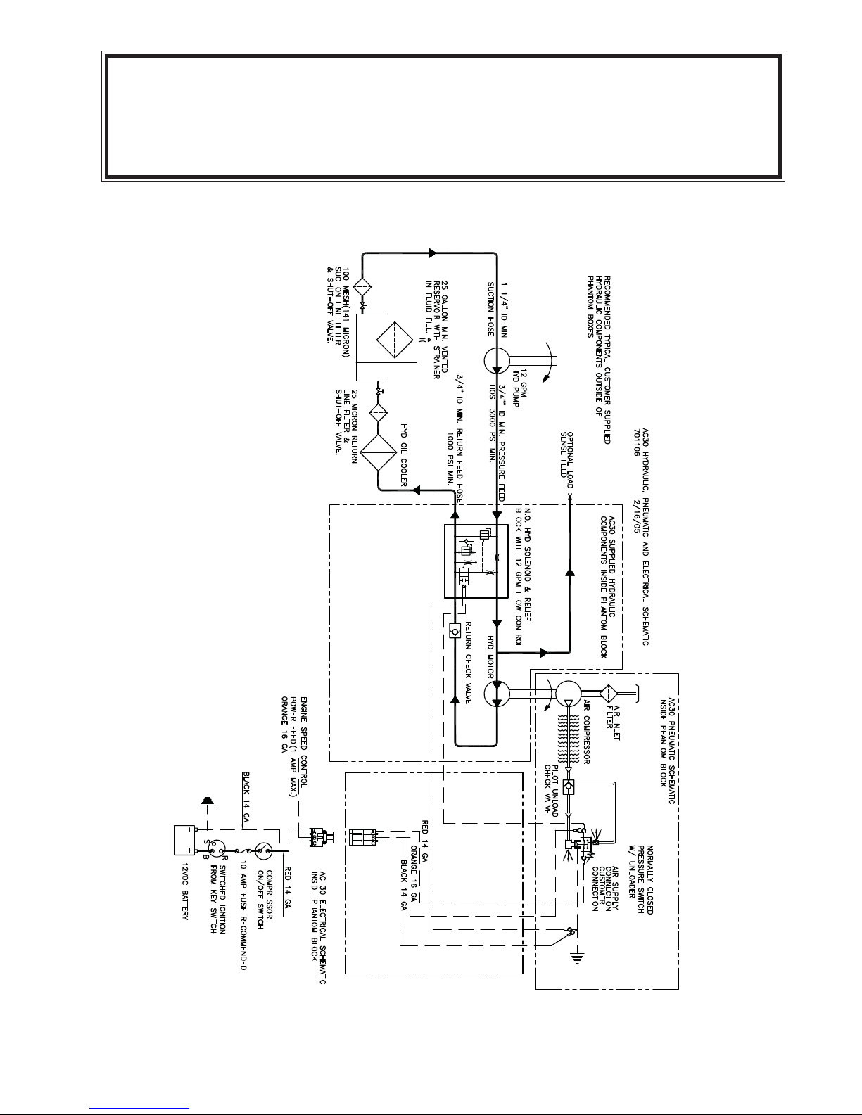
10/09
2-4.0.0
AIR/HYDRAULIC/ELECTRICAL
SCHEMATIC P/N: 701106
10/09
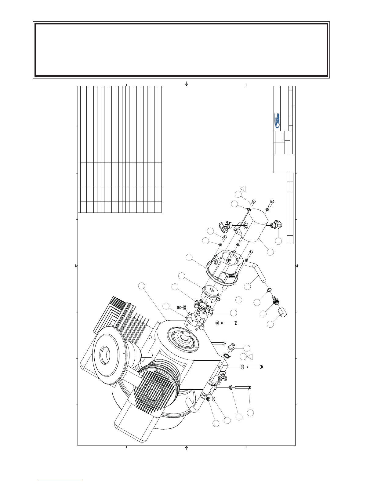
3-1.0.0
AC30A COMPR & PARTS SYS.
P/N: 200281-999
1
1
2
2
3
3
4
4
5
5
6
6
7
7
8
8
A A
B B
C C
D D
Parts List
DESCRIPTIONPART NUMBERQTYITEM
ELBOW, HYD 1/2 MJIC X -10 MSAE970408-08811
MOTOR, HYD 1.29 A 3/4-RD SP CCW HP30525812
WASHER, FLAT GR8 3/8938206-07183
NUT, NYLOC GR8 3/8-16925506-19844
HUB, DRIVE COUPLING R38(.750 DIA BORE).0005
30126615
SPIDER, DRIVE COUPLING R3830126716
WASHER, LOC 8MM
938808-20047
BOLT, HEX GR10.9 8MM X 30MM929208-300
4
8
COMPR, 35 PISTON AC30476019
ADAPTER, 1/2 BSPP X 1/2 NPT
302631110
BOLT, HEX GR8 3/8-16 X 3929806-300411
ADAPTER, HYD MTD TO AC30 COMPR
305767112
WASHER, LOC GR8 3/8937806-094213
BOLT, HEX GR8 3/8-16 X 1 1/4929806-125214
ADAPTER, 3/8 MBSPT X 3/8 FNPT
989206-038115
HOSE, .500 OIL DRAIN AC303026361.167 FT16
HUB, DRIVE COUPLING 35MMX10X8MM KEY
305434117
CLAMP, HOSE 3/4 WORM GEAR300033-075218
CAP, PIPE HEX 1/2 ZINC906030-020119
ELBOW, HYD 3/4 MJIC X -12 MSAE
970412-106120
CONNECTOR, 1/2 BARB X 1/2 MNPT974808-050121
SEAL, WASHER 1/2 MBSPP
308525122
SHEET
200281
11
OF
REV
2
COMPR & PARTS, AC30
AUTO CRANE
P.O. BOX 580697
TULSA, OK 74158-0697
N/A
PATH
MATERIAL
G:\Inventor Files\200k\200281.dwg
1/11/2006
NDD
DRAWN
CHECKED
1=2
D
DESCRIPTION
DWG NOSCALE
SIZE
UNMACHINEDSURFACES
FRACTIONAL
`
1/16
DECIMAL
`
.03
ANGULAR
`
1°
DO NOT SCALE
TOLERANCES
UNLESS NOTED
MACHINEDSURFACES
NOMINALDIM.
0.000 TO 1.000
`
.010
1.001 TO 5.000
`
.015
5.001 TO 10.000
`
.020
10.001& OVER
`
.025
THIS DRAWING AND ALL
INFORMATION THEREIN IS
THE PROPERTY OF
AUTOCRANE, IS
CONFIDENTIAL AND MUST
NOT BEMA DE PUBLIC OR
COPIED. IT IS LOANE D
SUBJECT TO RETURN UPON
DEMAND, IS NOT TO BE USED
DIRECTLY OR INDIRECTLY IN
ANYWAY DETRIMENTIAL TO
THE INTEREST OF AUT O
CRANE.
PROPRIETARY INFORMATION
2 ADDED 308525 3/11/2011 MCM
1REPLACED (2) 929806-100 WITH 929806-125 7/7/2008 MCM
REVISION HISTORY
REV DESCRIPTION DATE ENG
9
4
3
3
11
18
16
18
19 2
1
14
13
8
7
12
5
6
17
1
22
10
15
21
2
10/09
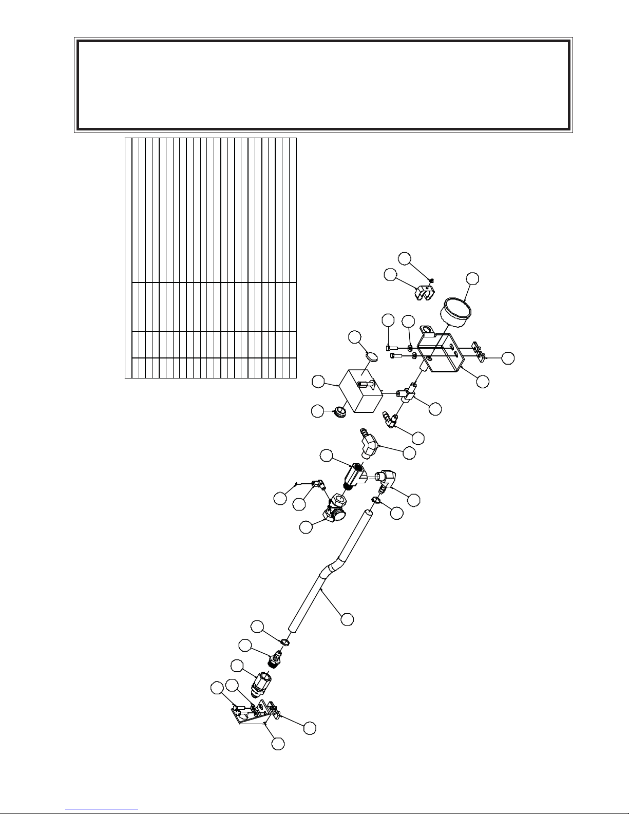
3-2.0.0
AC30A DISCHARGE & PARTS SYS.
P/N: 200283-999
Parts List
ITEM QTY PART NUMBER DESCRIPTION
1 1 962010-050 BULKHEAD, 5/8 JIC X 1/2 FNPT
2 1 9 75 1 04 - 01 2 EL BO W , C O M PRS N 1/ 4 TU BE X 1/ 8 M NP T
3 3.083FT 302636 HOSE, .500 OIL DRAIN GRAY 2
4 2 970308-050 ELBOW, HYD .500 BARB X .500 MNPT
5 1 964808-050 TEE, PIPE 1/2F X 1/2M X 1/2F
6 4 300033-075 CLAMP, HOSE 3/4 WORM GEAR
7 4 929104-100 BOLT, HEX GR5 1/4-20 X 1
8 4 938604-071 WASHER, FLAT GR5 1/4
9 1 305480 BRACKET, AIR DISCHARGE AC30 06 (REV 1)
10 4 961504-090 NUT, TINNERMAN 1/4-20
11 1 974808-050 CONNECTOR, 1/2 BARB X 1/2 MNPT
12 1 303815 VALVE, CHEC K 1/2
13 2 975200-025 INSERT, COMPRSN FITTING 1/2 BRASS
14 1 302613 CLIP, 1/2" HYD HOSE HOLDER
15 1 943103-025 RIVET, POP 3/16 X 1/2 ALUMINUM
16 1 305463 BRACKET, GAUGE & LIGHT (REV 2)
17 1 970308-025 ELBOW, HYD 1/2 BARB X 1/4 MNPT
18 1 77041369 SWITCH, PRESSURE WITH UNLOADER F
19 1 305162 CAP, 7/8 ID PLASTC
20 1 305799 GROMMET, 3/4 OD X 1/2 ID X 1/8 THICK
21 1 304998 GAUGE, 0-200 PSI 1/4 MNPT LIQUID FILLED
22 1 307054 TEE, .250MNPT X .250MNPT X .250FNPT
NS 1.083FT 89034176 TUBE, AIR BRAKE .25
14
15
4
4
6
13
2
12
6
11
1
7
8
10
9
4
21
10
16
8
7
22
17
18
19
20
5

10/09
3-3.0.0
AC30A FRAME & PARTS
P/N: 200280-999
Part s List
ITEM QTY PART NUMBER DESCRIPTION
1 1 970508-106 CONNECTOR, 1/2 MJIC X -12 MSAE
2 1 970512-106 CONNECTOR, 3/4 MJIC X -12 MSAE
3 1 305479 FRAME, AC30 06 (REV 1)
4 4 300540-001 ISOLATOR, 60A HARD BULLET (REV 2)
5 4 300541-001 WASHER, ISOLATOR 60A HARD (REV 2)
6 2 9 29 1 04 - 32 5 BO LT , H EX G R 5 1/4 -20 X 3 1 /4
7 4 9 38 6 04 - 07 1 W AS HER, FLA T G R 5 1/4
8 1 80056-13-12 KIT, HYD VALVE BLOCK 13GPM FLOW CONTROL
9 2 988912-106 PLUG, 12 SAE PLASTIC
10 4 961504-090 NUT, TINNERMAN 1/4-20
11 1 304762 BRACKET, VALVE BLK 35 PISTON A (REV 2)
12 2 9 29 1 04 - 10 0 BO LT , H EX G R 5 1/4 -20 X 1
13 1 304930 PLATE, VIBRATION ISOLATOR AC30
NS 1 3 06 8 12 - 21 5 OR I FIC E, SI LV ER .2 15
1
2
3
4
5
6
7
8
9
10
11
7
12
13
10
200280-999 (REV 1)
NOTE:
WHEN REPLACING HYDRAULIC
VALVE BLOCK (P/N 80056-13-12),
YOU MUST REMOVE ORIFICE
(P/N 306812-215) FROM THE OLD
BLOCK AND INSTALL ON THE
NEW BLOCK.
10/09
3-4.0.0
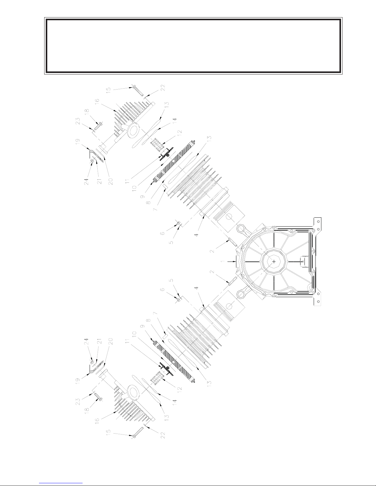
AC30A CYLINDERS & VALVES

10/09
II = PART OF VALVE KIT
III = PART OF PISTON + RINGS + CYLINDER KIT, LOW PRESSURE
IV = PART OF PISTON RING KIT
VI = PART OF PISTON, CYLINDER HEAD ASSEMBLY LH
VI I= PART OF PISTON, CYLINDER HEAD ASSEMBLY RH
ITEM KITS QTY P/N DESCRIPTION
1 - 1 N/A CRANKCASE ASSEMBLY
2 - 8 755080-001 SCREWED STUD
3 III, VI, VII 1 N/A PISTON ASSEMBLY
4 III, VI, VII 1 N/A CYLINDER
5 - 8 755080-002 WASHER
6 III, IV, VI, VII 8 755080-003 LOCK NUT
7 III, VI, VII 4 755080-004 PIN
8 II, VI, VII 2 N/A SUCTION DISC
9 VI, VII 2 755080-005 VAVLE SEAT
10 II, VI, VII 2 N/A DELIVERY DISC
11 VI, VII 2 755080-006 GUARD
12 II, VI, VII 2 755080-007 SPRING
13 II, VI, VII A/R 755080-008 CORD
14 II, VI, VII 2 755080-009 O-RING
15 VI, VII 10 755080-010 BOLT
16 VI 1 755080-011 CYLINDER HEAD LLP
17 VII 1 755080-012 CYLINDER HEAD RLP
18 - 4 755080-013 BOLT
19 - 1 REF INLET SILENCER (SEE Aw-461)
20 II 2 755080-014 GASKET
21 - 4 755080-015 WASHER
22 VI 10 755080-002 WASHER
23 - 4 755080-016 WASHER
24 II 4 755080-017 LOCK NUT
3-4.1.0
AC30A CYLINDERS & VALVES
Other manuals for AC30A
1
Table of contents
Other Auto Crane Air Compressor manuals


Popular Air Compressor manuals by other brands

Gardner Denver
Gardner Denver L Series Operating and service manual

FScurtis
FScurtis FCT02C48V3 Series Operating instructions and parts manual

Powermate
Powermate LA1683066 Operator's & parts manual

Metabo
Metabo HWW 3000/ 20 S operating instructions

Champion
Champion D15 Installation and start-up data

Easylife
Easylife EL5408 instruction manual

VIAIR
VIAIR 40045-400P-A user manual

Certa
Certa CT150ARCMPA quick start guide

NorthStar
NorthStar M36029L Installation, operation and maintenance manual

DeVilbiss Air Power Company
DeVilbiss Air Power Company 102D owner's manual

Sullair
Sullair ShopTek ST45 Operation & maintenance manual

ISANTA
ISANTA Senco AC19306BL operating instructions


