Auto-Trail 2006 User guide

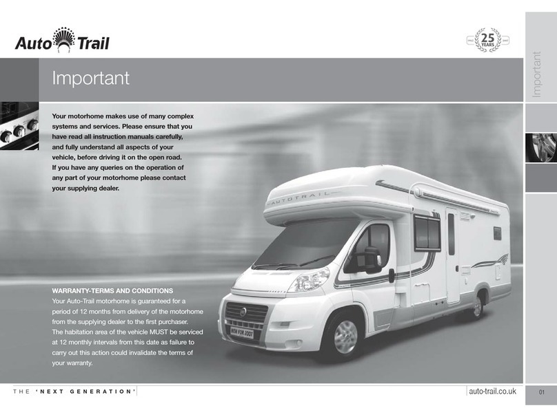
Your motorhome makes use of many complex
systems and services. Please ensure that you
have read all instruction manuals carefully, and
fully understand all aspects of your vehicle,
before driving it on the open road.
If you have any queries on the operation of
any part of your motorhome please contact
your supplying dealer.
1
Important
Final 2006 AT Handbook 1/12/05 12:06 pm Page 1

Model
Date Purchased
Supplying Dealer
Sales Person
Telephone Number
Tyre Pressure
Radio Code
Exterior Door Key Number
Water Filter Key Number
Vehicle Build Number
2
Useful Information
Final 2006 AT Handbook 1/12/05 12:06 pm Page 2

Name Phone Number
3
Useful Information
Final 2006 AT Handbook 1/12/05 12:06 pm Page 3

Section Pages
1. Introduction 5
2. Preparing For The Road 6 - 7
3. External Features 8 - 9
4. Driving Your Motor Home 10 -11
5. On Site 12
6. Gas: Services 13 -15
7. Gas: Appliances 16 - 25
8. Diesel Heating System 26 - 27
9. Electricity: Services 28 - 38
10. Integrated Entertainment System 39
11. Water: Services 40
12. Water: System 41 - 43
13. Water: Appliances 44 - 46
14. General Care 47 - 48
15. Fire And Safety 49
16. Security/Points Of Law 50
17. Winter Laying Up 51
18. Guarantee/Extended Warranty 52
19. Annual Check List 53 - 56
20. Good Neighbour Guide 49 - 51
21. Wiring Diagram 60 - 65
22. Vehicle Specifications 66
23. Weights Chart 67
4
Contents
Final 2006 AT Handbook 1/12/05 12:06 pm Page 4

Auto-Trail welcomes you to the ranks of Auto-Trail owners.
This handbook has been designed to enable you to derive
the maximum benefit and enjoyment from your motor home;
its information will be beneficial to experienced and new
caravanners alike.
Note:
It is important that this handbook accompanies the motor
home so that any future owner has the benefit of all the
relevant information.
This handbook is intended to give a brief overview of you
motor home and its services.You are advised to read all
individual appliance instructions which will be found in the
grey information wallet supplied with your vehicle.
ALL enquiries regarding your motor home should be
addressed, initially, to the dealer from whom the vehicle
was purchased.
Your motor home is designed to give many years of use.
Regular maintenance is, however, necessary to ensure
trouble free service.Your Auto-Trail dealer is equipped to
offer service facilities, repair work and any parts you may
require.
Always consult your Auto-Trail dealer before additional
equipment is fitted to ensure the appropriate fixing support
is available.
That when additional equipment is fitted the weight of that
equipment and any accessories it is designed to carry will
reduce the payload accordingly. Never exceed the
manufacturers Gross Vehicle Weight which can be found
on the plate in the engine compartment. In any
correspondence, the motor home serial number should be
quoted.This can be found on the nearside plate by the
entrance door.
Please note:
Every effort is made within this handbook to accurately reflect
and describe our motor homes (purchased and stored on the
mainland). However, our policy of continued improvements,
and change in the market supply conditions means that we
reserve the right to alter specifications without prior notice.
Some materials used in the production of our motor homes
can result in variations in the figures quoted relating to
weights and measurements.
When exterior storage lockers are fitted please be aware that
in certain climates moisture may enter these compartments.
As the interior of your vehicle is predominantly wood, there
may be some expansion under certain climatic conditions.
Your supplying dealer is responsible for all aspects of
customer care. As all vehicles are supplied with a
comprehensive warranty, please ensure the dealer has fully
explained all aspects of your motor home's operational
systems and the necessary servicing requirements. Should
you require assistance your supplying dealer is fully
conversant with the correct procedures.
Modifications to your vehicle
Please check with your supplying dealer before carrying out
any modifications to your vehicle.Any unauthorised
modifications carried out by a third party could effect the
terms of your warranty agreement. If in doubt ask.
So not to invalidate your warranty, always have your vehicle
serviced by your selling dealer.
5
1. Introduction
Final 2006 AT Handbook 1/12/05 12:06 pm Page 5

Pre-Load Checklist
• Ensure all articles are stowed securely. Do not store tins,
bottles or heavy items in overhead lockers.
• Close and secure all lockers and cupboard doors.
• Secure all bunks.
• Close and secure all roof lights.
• Store main table in transit position.
• Ensure fridge is on 12V operation and set door lock.
• Close and latch all windows.
• Never drive with windows on night setting.
• Leave all curtains and blinds open to aid visibility.
• Ensure gas bottles are correctly positioned, secured and
turned off.
• Secure battery.
Loading and Distribution of Weight in the Motor Home
• Load heavy items down near the floor mainly over or
between axles.
• Load evenly right to left.
• It is recommended that the table is stored on the floor
between the beds or in the transit position whilst the
vehicle is in motion.
• The maximum loading payload is stated in ‘Your Vehicle’ at
the back of this manual. To ensure this is distributed evenly
the maximum capacity of each axle is indicated on the
chassis plate which is located either in the engine bay or
under the drivers seat.
Roof Rack (If fitted)
Please be advised that the maximum recommended weight
that should be carried on a roof rack is 40kg. Please be
advised that in certain climatic conditions the fibreglass roof
may become slippery. Please take extreme care when
walking on your vehicle roof.
Apache Roof Bars
Please note that the standard roof bars fitted to the Apache
model range should not be used for load carrying. Auto-Trail
recommends that an additional standard roof rack be fitted
for the carrying of any loads.
Frontier Rear Under Floor Storage Compartment
Please be advised that the maximum weight that should be
carried in this compartment is 30kg.
Bicycle Carrier (If Fitted)
Auto-Trail recommend that if a bicycle carrier is fitted to your
vehicle it should be capable of carrying no more than two
cycles.
The Frontier model is designed to use a specially designed
cycle carrier. Details of this are available through your
Supplying Dealer.
Never Exceed The Maximum Authorised Weight
Specified On The Carrier.
6
2. Preparing For The Road
Apache 700 shown with roof bars
Final 2006 AT Handbook 1/12/05 12:06 pm Page 6

Tow Bars
Various suppliers manufacture tow bars that can be fitted to
your Auto-Trail vehicle. Please check with your tow bar
supplier that the carrier that you fit to your vehicle meets your
requirements, and does not contravene any road traffic
regulations.
Final Checklist
• Secure all loose items.
• Close all interior doors.
• Place tip up sink in open position.
• Ensure that seat swivels (if fitted) are locked in the forward
facing position.
• Turn off all gas appliances, except those heating
appliances designed to function while the vehicle is
in motion.
Stability
All models manufactured by Auto-Trail are of well-balanced
design the most common causes of poor stability include:
• Incorrect tyre pressure.
• Poor weight distribution.
Tyre Pressures
Always adhere to the tyre pressures as stated in the chassis
manufacturer's handbook.Always inflate to a fully laden
condition.
Base Vehicle
Please make reference to the base vehicle handbook for
matters relevant to the motor caravan as a road vehicle.
7
2. Preparing For The Road
Final 2006 AT Handbook 1/12/05 12:06 pm Page 7

AExterior door retaining catch when open
BFolding step
CFridge vents
DAwning light (where fitted)
EStatus T.V. aerial (omni directional, where fitted)
FFront marker lights
8
3. External Features
F
E
A
CB
D
Final 2006 AT Handbook 1/12/05 12:06 pm Page 8

ASpare wheel and battery access panel
BExternal ladder
CLockable external access door to toilet waste tank
DLockable gas cylinder compartment
(operated via an internal remote lever on Cheyenne
and Frontier models)
EHigh level brake light (where fitted)
FLockable fresh water filler
9
3. External Features
B
E
A
FCD
Final 2006 AT Handbook 1/12/05 12:06 pm Page 9

Speed Limits
Always adhere to the speed limits.
Driving Abroad
Please ensure that you are familiar with the relevant laws and
regulations that apply in the countries in which you choose to
travel. Different Mainland European countries have different
laws and regulations and it is your responsibility to ensure
that your vehicle complies with these regulations and that you
drive within the law.
Pulling Off
• Operate the clutch smoothly.
• Change gears smoothly.
• Try not to jerk the clutch.
Motor Home Handling
• Allow for motor home being wider than a car.
• Do not bump the kerb with motor home wheels.
• When passing other vehicles allow more clearance than
in normal driving.
• Allow longer to speed up when overtaking.
• Allow for vehicle being longer than a car.
• Do not swing out suddenly.
• Carry out all manoeuvres as smoothly as possible.
• Use nearside wing mirror to check motor home has
cleared when overtaking.
Reversing
Proficiency at reversing can only be achieved with practice
and should first be attempted in a large open area. Courses
are run by many organisations.
Reversing Sensor
Your vehicle may be fitted with either a visual or audible
reversing aid.These aids are designed to assist drivers
attention only during reversing of the vehicle, they are not
intended to replace a drivers self judgement.
Auto-Trail will not accept any responsibility for any accident
caused by a drivers negligence.
Please note
If a bicycle carrier or tow ball is fitted to your vehicle it could
effect the operation of the reversing sensor.
Driving
Reduce speed when:
1. In high or cross winds.
2. Going downhill.
3. In poor visibility.
High-speed vehicles cause air buffeting, extra care must be
taken when passing or being passed. As much space as
possible should be given.
10
4. Driving Your Motorhome
Auto-trail fitted Reversing Camera
Final 2006 AT Handbook 1/12/05 12:06 pm Page 10

Changing a Wheel
• Remove wheel trims. Use the wheel brace to slacken off
wheel nuts on the wheel to be changed.
• Position the jack under the axle or at the appropriate
jacking point.
• Jack up motor home until the wheel for removal is just
off the ground.
• Remove wheel nuts and wheel.
• Fit the spare wheel (located in the carrier) and reverse
the above procedure.
• Tighten all nuts equally.
Note:
Never, under any circumstances, use the corner steadies to
jack up the motor home. Instead, use a bottle jack, scissor or
air jack under the axle tube as near as possible to the main
chassis member.
Alloy Wheels
It is vitally important that when you get replacement tyres
fitted to your vehicle the valves that are used are capable of
withstanding the high pressures associated with motorhome
tyres. Usually only ‘bolt through’ steel type valves can
withstand the pressures associated with motorhome tyres.
Your vehicle may be fitted with alloy road wheels but a
steel spare wheel. Please note that the steel spare
wheel will require different wheel nuts (supplied with vehicle)
to the ones used to fit the alloy wheels, these cannot be
interchanged.
Note: Check and observe site regulations.
11
4. Driving Your Motorhome
Alloy Wheel with New tyre
Final 2006 AT Handbook 1/12/05 12:06 pm Page 11

Selecting a Pitch
Do not pitch in a position in which your vehicle will obstruct
others coming in.
Try to choose an area that is dry, reasonably level and,
preferably, with a hard base.
If you have no alternative but to pitch on a slope, ensure that
when you leave, you are driving down the slope.
It is always good practice to check the wheels of the motor
home when parked on a slope or a slippery surface although
the brakes are applied.
In poor site conditions:
1. Keep engine revs low; start in second gear if possible to
prevent the wheels digging in.
2. Steer as straight as possible.
Levelling The Motor Home
Levelling must be carried out in both directions in order for
the refrigerator and other equipment to function correctly.
Lower the corner steadies, using the special Auto-Trail brace,
until they are in firm contact with the ground.
DO NOT use the corner steadies as a jack; they are only a
means of stabilising the motor home.
Levelling pads or boards should be used under steadies and
wheels where the ground is soft or uneven.
Check whether the motor home is level both front and rear.
In extreme cases where it is necessary to raise a wheel off
the ground for levelling purposes, further support should be
applied so that the corner steadies do not take any undue
strain.
12
5. On Site
Final 2006 AT Handbook 1/12/05 12:06 pm Page 12

GENERAL INFORMATION
There are four gas appliances in the motor home: refrigerator,
water heater, hob and oven. Gas flows to a set of safety
shut-off valves controlling each appliance.The valves allow
isolation of a single appliance without affecting the operation
of the other equipment.
Each appliance is fitted with a FLAME FAILURE DEVICE it is
necessary to keep the gas control knob (appliances other
than the water heater) depressed for 15 to 30 seconds after
ignition to activate the device.
If the gas stops flowing to the appliance or the flame is
extinguished, the flame failure device automatically closes
the valve to shut off gas supply to the appliance.
Each appliance has a gas isolation valve fitted into the gas
system to enable each appliance to be turned off from the
gas supply for routine servicing or if a fault should develop.
Please familiarise yourself with the location of these isolation
valves which are clearly marked with their open and closed
position, and which appliance each individual valve operates.
Please make sure all gas appliances are working efficiently to
the recommendations of the appliance manufacturer.
TYPES OF GAS
Butane
Butane is supplied in the UK in green or blue bottles.
Continental bottles usually have a male left hand thread
similar but not identical to UK butane.
Butane has a recommended service temperature of down to
2°C but will work below that.
Propane
Propane is supplied in red or partly red bottles that have a
female left hand thread connector. Germany and Austria
supply propane with a male connection.
Propane is suitable for use at temperatures as low as -30°C
and is therefore ideal for all winter caravanning.
Cylinder Compartment
Your vehicle is designed to take either a 13kg or 7kg gas
bottles, this is dependant on the model you have chosen.
The compartment has low level ventilation to ensure the
safe operation of the cylinders and should not be blocked
or obstructed in any way.
Please ensure that any additional items stored in this
compartment are secure and cannot damage any of the
pipe work or fittings.
Changing a Gas Cylinder
Ensure the cylinder valve is fully closed before disconnecting
the high pressure hose from the bottle.
Release the gas bottle retaining straps that restrain the gas
bottles into the compartment.
Carefully remove the gas bottles from the compartment
taking care not to damage any pipe work or fittings in the
process.
Refitting a gas bottle is a reversal of the above procedure,
but please ensure that the high pressure hose is connected
correctly before opening the cylinder valve.
13
6. Gas: Services
Gas Cylinder
Final 2006 AT Handbook 1/12/05 12:06 pm Page 13

Pressure Regulating Device
Your vehicle is fitted with a bulkhead mounted pressure
regulating device that will provide a working gas pressure of
30 mbar (1.5 kg of gas per hour). All appliances installed by
Auto-Trail are designed to work within this pressure range.
Please ensure that any additional appliances not fitted by
Auto-Trail are capable of working within this pressure.
Gas Hoses
Your supplying dealer will advise on the correct type of high
pressure hose to connect your gas cylinder to the pressure
regulator.This will depend on the type of gas cylinders you
choose to carry in your vehicle.
The tightness of flexible gas hose, joints and connections
must be checked regularly.
Hoses should be routinely replaced at intervals not exceeding
5 years or as recommended in the manufacturers
instructions.Any hose that shows signs of splitting, wear or
damage should be replaced irrespective of age.
The gas hose supplied by your dealer should not be
extended in any way. Gas bottles should not be stored
outside your vehicle
GAS SAFETY ADVICE
Facts About LPG
There is a danger if all air and oxygen is excluded.
LPG has been given a smell by the manufacturers to aid
in the identification of leaks.
Awning Space LPG Appliance Exhaust
No danger is caused if the LPG exhaust from the refrigerator
vents into an enclosed awning. If totally enclosed, space
heaters may produce enough exhaust to pollute an enclosed
awning to discomfort levels. In extreme cases, carbon dioxide
build up could reach a dangerous level.
Motor home owners are advised to allow some ventilation
when such appliances are in use.
Precautions
If a leak is suspected:
• Turn off the gas supply from the cylinder using the isolation
valve situated on the top of the gas bottle.
• Never search using a match.
• Always use soap solution, or its equivalent, when testing
connections.
• Do not operate any electrical apparatus, especially light
switches.
• If leak is not obvious, the caravan should be evacuated and
qualified personnel consulted.
• Remember that gas is heavier than air therefore sinks to
the lowest point.
• Avoid naked lights when connecting or changing a
cylinder.
• Check the flexible hose frequently.
• Keep bottled gas containers outside and protect against
frost. If storage inside is the only option then keep away
from heat sources.
14
6. Gas: Services
Final 2006 AT Handbook 1/12/05 12:06 pm Page 14

Ventilation
Low-level ventilations is provided from either the passenger
and drivers door, or behind the drivers seat. High-level
ventilation is provided by sky lights located in the roof of
the vehicle.
All ventilation complies with European Standards and vents
should not be obstructed in any way as this could lead to
insufficient fresh air. If this occurs, the confined atmosphere
becomes deficient in oxygen which leads to the formation of
the highly poisonous gas carbon monoxide (CO). CO is
odourless, colourless and tasteless and will rapidly cause
unconsciousness followed by death.
If this happens there is little or no warning prior to collapse.
Note: There is no danger providing the ventilation is not
blocked and any meshes are cleaned regularly.
Roof Mounted Flue Installations
All flue installations should be inspected for corrosion once
a year throughout their length. If any sign of perforation is
detected, the flue should be replaced. Ensure that the
replacement flue is of an correct type and that it is installed
by an approved engineer.
Combustible Materials
Care should be taken when storing any combustible
materials near any heat source (eg space heater).
Warning
Please note that internal outlet sockets should only be
used with dedicated appliances.
Please note that no appliance should be used outside the
motorhome if connected to an internal socket.
Portable Heaters
Never use portable cooking or heating equipment, other than
radiant heaters that are not of the direct radiant type, as it is a
fire and asphyxiation hazard.
Under no circumstances should a cooking appliance be
used for heating the vehicle.
15
6. Gas: Services
Final 2006 AT Handbook 1/12/05 12:06 pm Page 15

COOKING APPLIANCES
Your vehicle is fitted with either a Spinflo four gas burner and
oven, or three gas burners and one 230V mains hot plate
and oven.
The gas burners are adjustable between simmer and full
flame, and the oven temperature ranges from 130ºC to
240ºC.The electric hot plate has six temperature settings.
Both appliances are suitable for LPG gas only and no other
types of gas should be used:
User Instructions
Ensure the gas cylinder is turned on. In event of a gas smell,
turn off at the cylinder and contact supplier.
Operation: Gas
Select required burner; depress the control knob and light
with either a match or the ignition system if provided.When
the burner has lit keep the knob depressed for a minimum of
15 seconds to ensure that the flame is established and the
flame failure device is activated.
If the flame goes out when the knob is released, the
procedure should be repeated holding the knob in for slightly
longer.To turn off the burner turn the knob clockwise until the
dot on the knob lines up with the dot on the control panel.
Warning when attempting to light the oven, the ignition
device must not be operated for more than 15 seconds.
If after this time the burner has not lit, stop operating the
device, open the oven door and wait at least a minute before
attempting further ignition of the burner.
If a burner accidentally extinguished, turn off control and do
not attempt to re-light for at least one minute.
Hotplate
Pans with a diameter of up to 22cm are suitable for use on
this appliance.The pans must not overhang the pan support.
Grill
When using the grill, the grill pan must always be positioned
directly beneath the gas burner and the door must be
open.The glass lid must be in the raised position while
grilling. During preheat, if required, the grill pan should be
left in position to protect the base lining.
Caution: Accessible parts may become hot while grill is in
use. Young children should be kept away.
Oven: Cooking Hints
• Remove all accessories and packing from the oven and
clean the interior using soap and water prior to first use.
• Place the oven shelf in the required position and close the
door. Set control knob to gas mark 5 and heat the oven for
approximately 20 minutes to eliminate any residual factory
lubricants that may cause unpleasant smells during
cooking.
• Meat must be fully thawed before cooking.
• Chilled and frozen pre-cooked foods should be thoroughly
heated and attention should be paid to the manufacturer's
instructions.
• To achieve best results preheat the oven at the correct
temperature for 10 minutes (Belling) or 20 minutes (Spinflo)
prior to use.
• When roasting with aluminium foil care must be taken that
the foil does not impair circulation or block the oven flue
outlet.
16
7. Gas: Appliances
Multi-Fuel cooker with Grill and Oven
Final 2006 AT Handbook 1/12/05 12:06 pm Page 16

• The oven shelf is designed to allow good circulation at the
rear of the oven and are fitted with a raised bar to prevent
trays or dishes making contact with the back of the
oven.To remove the shelf, pull forward until it stops, raise
the front and remove.
• The baking tray and roasting dish provided are the largest
that should be used in the oven as larger items may affect
the circulation and heat distribution.
The cookers are fitted with a thermostat that gives controlled
temperatures throughout the cooking range.The gas mark
relates to the temperature at the centre of the oven, with
higher temperatures towards the top and lower temperatures
towards the bottom.
This variation is approximately equivalent to one gas mark.
These zones can be used to cook, simultaneously, foods that
require different heat settings.
Cleaning
DO NOT USE ABRASIVE
CLEANERS OR POLISHES.
Your new oven will keep its good looks and work efficiently if
the following cleaning instructions are followed.
Painted parts: Use only a soft cloth with warm soapy water.
Vitreous metal: Inside the oven, grill compartment and
hotplate only. Use a cleaner recommended for vitreous
enamel or a soap filled pad, i.e. 'Brillo'.
Note: the oven and grill doors and the cooker trims are
painted and must only be cleaned with warm soapy water.
Chrome parts: Use warm soapy water or a brillo pad.
Glass: Use warm soapy water or a mild cream cleaner.
Extractor Hood (If fitted)
This is located above the hob, operation is as follows: Switch
1 works the light and switch 2 the fan.
Leaks
If a smell of gas becomes apparent, turn off supply at
cylinder immediately.
Extinguish all naked lights including cigarettes and pipes.
Do not operate electrical switches. All doors and windows
should be opened to disperse any gas build up.
As butane and propane are heavier than air, the gas will
collect at low level.The strong unpleasant smell will allow the
general area of the leak to be ascertained, check it does not
originate from an unlit appliance. Never check for leaks with a
naked flame; investigation should be carried out using a leak
detector soapy solution.
Maintenance
Little maintenance is necessary for this appliance other than
cleaning. This appliance must not be modified or adjusted
unless authorised and carried out by the manufacturer or
their representative. No parts other than those supplied by
the manufacturer should be used on this appliance.
17
7. Gas: Appliances
Final 2006 AT Handbook 1/12/05 12:06 pm Page 17

Refrigerator
DOMESTIC RM7361 see side panel for description
Note:The refrigerator is equipped to operate on mains power,
DC or liquid gas (propane / butane).The desired power
option is selected by means of energy selector switch (A).
Energy selector switch (A) has four settings:AC mains power,
DC (12V), Gas (liquid gas), OFF.
Electrical Operation (12V)
The refrigerator should only be used whilst the engine is
running, otherwise the on-board-battery would be discharged
within a few hours.
1Set the energy selector switch (A) to 12V.
2Operating display “C”, 12V lights “green”, the appliance is
now operating.
3Use rotary switch (B) to regulate the temperature in the
main refrigerator compartment. If the operating display fails
to light up the device is not operating.
Mains Operation (230V)
This option should only be selected where the supply voltage
is 230V, any different values may result in damage to the
appliance.
1 Set energy selector switch (A) to 230V.
2 Operating display “C”, 230V lights green, the appliance
is now operating.
3 Use rotary switch (B) to regulate the temperature in the
main refrigerator compartment. If the operating display
fails to light up the device is not operating.
Gas Operation
1 Open the valve of the gas cylinder.
2 Open the shut-off valve on the gas supply.
3 Set energy selector switch (A) to gas.
4 Set the rotary switch (B) to “MAX” position.
5 Use rotary switch (B) to regulate the temperature in the
main refrigerator compartment.
The ignition process is activated automatically, accompanied
by a ticking sound for approximately 30 seconds. On
successful ignition, the display LED (C) “GAS” lights
yellow.The refrigerator is now functioning.
In the event of a gas fault (eg gas cylinder empty), the
operating display (C) flashes yellow.
Switching the refrigerator off
Turn energy selector (A) to “OFF” position.The refrigerator is
now switched off.
Important: If you are leaving your vehicle for an extended
length of time (eg greater than two weeks) the energy
selector (A) should be turned to the “OFF” position. Failure to
do this could result in a fully discharged leisure battery which
could cause long term damage to the vehicle.
.
18
7. Gas: Appliances
Refrigerator
DOMESTIC RM7361
Energy Selection
A= Energy selection switch
B= Gas / electric thermostat AC / DC
C= Operating displays
A
C
C
Final 2006 AT Handbook 1/12/05 12:06 pm Page 18

THETFORD N150
Refrigerator Controls
A. Main switch ON/OFF
B. Mode selection switch
C.Temperature selection switch
D. Function LED
E. LCD Display
Thetford N150 Fridge Freezer Instructions
Switching on the refrigerator
1. Open the valve of the gas bottle
2. Open the taps of the gas supply
3. Press main switch (A). The function LED will turn blue
and all symbols on the LCD display will light up.
4. Use the mode selector switch to select the “Auto” function,
or one of the power sources that you want. The LCD
display will show you the option you have selected.
5. Set the desired refrigerator cooling level by means of the
cooling level selection switch (C). The LCD display will
show you the cooling level setting that you have selected.
POWERING WITH ELECTRICITY
Auto Mode
Mains voltage (230V)
This energy source will be selected if the mains voltage is
greater than 200V. This power supply requires a continuous
current of 12V to operate the electronic control system.
Direct Current (12V)
The SES system will select 12V powering only if a mains
voltage (230V) is unavailable, the vehicle engine is running
and a voltage higher than 11V is available. If a fault occurs
during electrical powering (230V or 12V), an error message
will not be shown on the display as long as another energy
source is available. The system will automatically switch to
the available energy source that has the highest priority.
Selecting Manually
Mains voltage (230V)
The LED on the main switch warns you whenever insufficient
voltage is available or if a fault occurs. If this happens, the
LED will change from green to red and flash once per
second and an error code is shown on the LCD display.
When sufficient current is available again, or the fault has
been resolved, the main switch LED will emit a steady
green light.
Direct current (12V)
The main switch LED warns you whenever your vehicle’s
engine is not running, or if a fault occurs, or in insufficient
voltage is available. If this happens, the LED will change from
green to red and flash once per second and an error code is
shown on the LCD display. Once the engine is running, or
the fault has been resolved, or sufficient voltage is available
again, the main switch will again emit a steady green light.
NB if the refrigerator has been manually set to operate at
12V, it will not automatically switch to another energy
source when your vehicle’s engine is not running. In this
case the refrigerator will stop cooling.
19
7. Gas: Appliances
C
A
BD
Final 2006 AT Handbook 1/12/05 12:06 pm Page 19

POWERING WITH GAS
Selecting gas in auto mode
The system will operate if;
- Mains voltage is unavailable;
- The vehicles engine is not running.
Once mains voltage (230V) is available again or the vehicle’s
engine is running, the system will switch to the available
energy source that has the highest priority of the fridge is
in auto mode.
If the refrigerator switches from 12V DC to gas operation
when in auto mode, the system will wait for about 15 minutes
before infighting the gas. During this time however, the gas
indicator light will come o. This delay is built in to avoid it
switching to gas operation whenever you stop to refuel your
vehicle. You can cancel the delay by immediately switching
the refrigerator off and on again.
If the system selects gas operation, the ignition will be
activated automatically. The gas will flow to the burner and be
lit by the electric ignition. If the flame goes out, the gas will
immediately be lit again.
Selecting gas operation manually
If the flame cannot be lit within 30 seconds, the gas supply
will stop and gas mode will be switched off. The LED will
start flashing every second and an error code is shown in the
LCD display.
Gas mode can be reset only if the refrigerator is switched off.
If you switch the refrigerator on again and the gas mode is
still not working, the LED of the manual gas mode will flash
to indicate that gas is unavailable and an error code is shown
in the LCD display.
Important! It is prohibited to use gas to power the
refrigerator while you are driving. If a road accident
results in fire, there is a danger of explosion. It is
prohibited to use gas to power the refrigerator in the
vicinity of petrol stations. If it takes longer than 15
minutes to refuel your vehicle, you should switch the
refrigerator off using the main switch (A).
Switching off the refrigerator
- Push the main switch (A).
- The blue LED will go out.
- The refrigerator is now completely switched off.
Travel Catch
Ensure that this is engaged whilst the vehicle is in motion.
The travel catch at the top of the door can be set in two
positions. In one position, the door is held tightly shut and
in the other, it is held slightly ajar so the fridge can be aired
when not in use.
20
7. Gas: Appliances
Thetford fridge freezer
Final 2006 AT Handbook 1/12/05 12:06 pm Page 20
This manual suits for next models
1
Table of contents
Other Auto-Trail Motorhome manuals
Auto-Trail
Auto-Trail Tracker User guide
Auto-Trail
Auto-Trail Motorhome Installation guide
Auto-Trail
Auto-Trail Excel User guide
Auto-Trail
Auto-Trail 2015 V-Line User guide

Auto-Trail
Auto-Trail V LINE 540 SE 2020 User guide
Auto-Trail
Auto-Trail Cheyenne User guide
Auto-Trail
Auto-Trail Tribute Series User guide

Auto-Trail
Auto-Trail FRONTIER User guide

Auto-Trail
Auto-Trail Motorhome User manual

