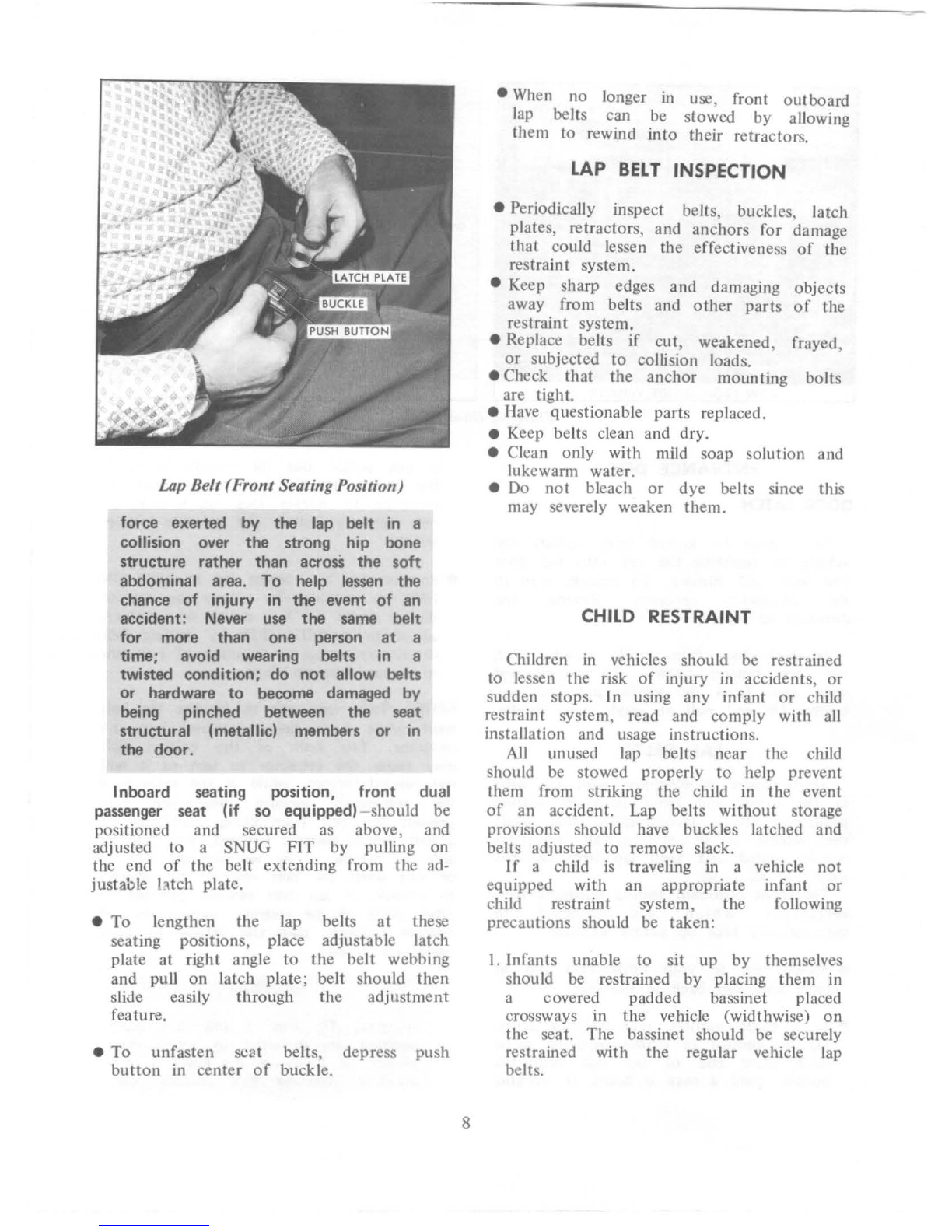
GMC 1976 TRANSMODE User manual

GMC:
1976
TRANS
MODE
X-7680A
OPERATING
MANUAL
MODELS
ZE06083
AND
ZE06583
IMPORTANT OPERATING,
SAFETY
AND MAINTENANCE INSTRUCTIONS
•
Part
No.
2003753

~--
A
WORD
TO
GMC
OWN
ERS
. • .
This manual has been prepared
to
acquaint
you
with the operation and
maintenance
of
only
the
chassis and
body
components
of
your
TransMode
Vehicle, and
to
provide important safety information.
It
is
supplemented by
convenient folders which provide additional information
on
vehicle
maintenance, emission control, and warranties.
We
urge you
to
read these
publications carefully and follow
the
recommendations
to
help assure
the
most enjoyable and troublefree operation
of
your vehicle.
When
it
comes
to
service, remember that
your
GMC
MotorHome dealer
knows
your
chassis and
body
components best and is interested in
your
complete satisfaction. Return
to
him for Guardian Maintenance Service and
any
other
assistance
you
may require.
GMC
Truck and Coach maintains a number
of
Zone Offices throughout
the
country. Should you have a problem
that
cannot be handled through normal
channels, follow
the
procedure presented in Section 6
of
this manual under
the
heading, "Owner Assistance".
We
would like
to
take this
opportunity
to
thank you for choosing a
GMC
product-and
assure you
of
our
continuing interest in
your
motoring pleasure
and satisfaction.
GMC
Truck & Coach Division
FOR
CONTINU
ING
SATISFACTION,
KEEP
YOUR
VEHICLE
ALL
GM.
GENERAL
MOTORS
PARTS ARE
IDENTIFIED
BY
ONE
OF
THESE
TRADEMARKS:

GMC
TRANSMODE
VEHICLE
Operating
Manual
This manual should be considered a permanent part
of
the
vehicle,
and
must remain with
the
vehicle
at
time
of
resale.
For
vehicles sold in Canada, substitute the name General Motors
of
Canada Limited, wherever
the
name
GMC
Truck and Coach Division
appears in this manual.
All
information, illustrations and specifications contained in this manual
ar
e based
on
the latest product information available at the time
of
publication. The right
is
reserved to make changes at any time without
notice.
TABLE
OF
Sect
ion
I Before Starting
You
r Vehicle
2 Starting and Operating Vehicle
Steering Column
Contro
ls
Floor
Controls .
Instrument
Panel and
Con
t
ro
ls
3 In Case
of
Emergency
4 Appearance Care
5 Service and Maintenance
GMC Truck & Coach Division
General Motors Corporation
Pontiac, Michigan
48053
CONTENTS
Page
5
10
12
17
19
33
39
.. 45
6 Specifications, Owner Assistance, Index, Gas Station Information
67

IMPORTAN
T I
NFORMATION
ON
VEH
ICLE
L
OADING
OVERLOADING
CAUTION
The components
of
your
vehicle
are
designed
to provide satisfacto
ry
service
if
the vehicle
is
not loaded
in
excess
of
either the
Gross
Vehicle Weight Rating (GVWR) or
the maximum Front
and
Rear
Gros
s
Axle
Weight
Ratings
(GAWR
's)
specified on the vehicle identification
number
(VIN)
plate located
beh
ind
the
right
front
access
door.
Overloading
can
create
seriou
s
potential safety
hazards
and
can
al
so
shorten the
service
life
of
your
vehicle
. Your dealer
can
advise
you
concerning proper loading conditio
ns
of your vehicle.
MAXI
MUM
FRONT
AND
REAR
AXLE
WEI
GHTS
(
AS
MANUFACTURED)
The weight
of
the cargoload must be
properly distributed over
both
the front
and rear axles, although
not
necessarily
evenly. The (VIN) plate shows the
maximum weight t
hat
the front axle can
carry
(front
GAWR) and the maximum
weight
that
the rear axle (rear GA
WR)
can
carry.
Th
e GVWR represents
the
maximum
permissible loaded weight
of
the
vehicle
and takes into consideration the engine,
transmission, frame, brake, axle and tire
capabilities. Actual front and rear end
weights
at
the
ground can only
be
determined by weighing the vehicle. This
can be accomplished through highway weigh
stations or
other
such commercial facilitie
s.
For
assistance in this regard, consult
your
GVWR RATING 1
0,500
LBS.
REAR
GAW
R
7,000
LBS
.
REAR
CARGO 3,
900
LBS.
&
PASS
.LO
AD
TOTAl
7,000
LBS
.
MAXIMUM TOTAL WEIGHT AT GROUND 10,500 L
BS
.
*Curb
weight
is
the
maximum
weight
of
the
vehicle
(as
manufactured
by
GMC)
without
driver,
passengers,
or
cargo
but
does
include
fuel
and
coolant.
Vehicle Loading
(23'
Model)
2

GVWR RATING
11
,700
LBS.
,...,
J-1.1
k"lt
I gI yfr
I
~PS
k'fr
REAR
GAWR
7,500
LB
S.
I'''
k~
1
~
oV
~6--
MAXIMUM TOTAL WEIGHT AT GROUND
11,700
LB
S.
·; 1
Of
K~
5
~07
1(
..
*Curb
weight
is
the
maximum
weight
of
the
vehicle
(as
manufactured
by
GMC)
without
driver,
passengers,
or
cargo
but
does
include
fuel
and
coolant.
Vehicle Loading
(26
' Model)
dealer. Care should also be exercised
to
see
that
the cargoload
is
distributed
on
both
sides
of
th
e centerline
of
the
vehicle
as
equally as possible.
EFFECT
ON
WARRANTY
Your New Vehicle Warr
anty
does
not
apply
to
any
part
of
your
vehicle
"w
hich has
been subject
to
misuse." Any part which
fai
ls
because
of
overloading has been
subject
to
misuse.
ALLOWABLE
LATERAL
WEIGHT VARIATION
The independent suspension
on
this vehicle
could be adversely affected by an
unbalanced load
on
either side
of
vehicle.
The allowable
front
lateralweight variation is 250
pounds. The allowable rear lateral weight
variation is
600
pounds.
3
VIN
(Vehicle Identification Number) Plate
The vehicle identification
number
plate
shows
the
GVWR and the
front
and rear
GAWR's for the vehicle
to
which they are
attached.
Gross Vehicle Weight (GVW) is
the
weight
of
the vehicle itself, all items added
to
the
vehicle after
it
has l
eft
th
e factory, the
driver and all occupants, and everything
0
GENERAL
MOTORS
CORPORATION
0
WARRANTY
MAY
BE
VOID£D
IF
WEIGHT
EXCEEDS
ANY
OF
RATINGS
SHOWN
.
GROSS
VEHIClE
WEIGHT
INClUD£S
WEIGHT
OF
BAS£
VEHIClE
,
All
ADD£D
EQUIPMENT
,
DRIVER
AND
PASSlNGERS
,
AND
All
PROPERTY
lOADED
INTO
OR
ONTO
VEHIClE.
RATINGS
IN
POUNDS
·
AS
MANUFACTURED
GMJSS
Y!.HICLE
WE
IGHT
FOil
THIS
Y!.HICLE
MAXIMUM
FROIIT
ENO
WEIGHT
AT
GIIOU
NO
MAXIMUM
REAli
ENO
WEIGHT
AT
CROUNO
Y!.
HICLE
IOENTIFICATIOft
NO
.
0 0
Vehicle Identification Plate

that
is loaded
into
(or
onto)
the
vehicle.
The G
VW
must
not
exceed the G
VWR
and
the front and rear weights
of
the
loaded
vehicle
must
not
exceed
the
front and rear
GAWR's.
CAUTION
When using your vehicle
to
transport
luggage
or
other cargo, it
is
recommended
that
the articles
be
secured
in
place. This precaution
wi
II
help prevent such items from
becoming dangerous projectiles in the
event
of
an accident.
TIRES
It
is
important
that
the
tires on
your
vehicle be
of
the
proper
size, and be
properly inflated.
It
is
important
to
avoid
over-inflation as well as under-inflation. See
the SERVICE AND MAINTENANCE section
for
proper
tire inflation pressures.
For continuing satisfaction
keep
your
vehicle
all
GM
.
General
Motors Parts
are
identified by
one
of
these
trademarks
:
4

SECTION
1
BEFORE
STARTING
YOUR
VEHICLE
DRIVER
CHECKLIST
Before Entering Vehicle
1.
See
that
windows, mirrors and lights are
clean.
2. Visually note inflation condition
of
tires.
3. Check
that
area
to
rear
is
clear
if
about
to back up.
Before
Driving
Off
1.
Lock all doors.
2. Position seat.
3. Adjust inside and outside mirrors.
4. Fasten seat belts.
5. Check
that
warning bulbs light when key
is turned to
start
position.
6. Release parking brake (and see
that
brake warning light turns off).
7.
Be
sure you understand
your
vehicle and
how
to
operate it safely.
REMINDER: Always lock entrance
door
when driving for greater security in
the
event
of
an accident,
to
help keep
children
from
opening door,
and
for
greater
security against
entry
by
unwelcome persons while momentarily
stopped.
INSIDE
REARVIEW
MIRROR
Switch inside mirror to night position
to
reduce glare from following headlights.
To
raise
or
lower mirror
to
achieve
desired field
of
view, grasp mirror and
exert sufficient pressure
by
pushing
or
pulling up,
down
,
or
sideways.
5
KEYS
Two sets
of
keys are furnished with
your
vehicle. Each key has a different cross
section so
that
it
can be inserted only in
certain locks.
Key
with
Square
ll
ead-For ignition switch
only.
Key with Oval Head-For
door
lock, glove
box and
othe
r locking compartments.
The code number
of
each key
is
stamped on
the
"knock
out"
plug in
the
key head.
Your
dealer removed these plugs
and placed them with the spare set
of
keys in the special key envelope
that
was
given
to
you
at
the time
of
delivery.
For
your
protection:
• Record the numbers
on
the key envelope
and discard
the
key plugs.
• Keep the key envelope in a safe place
such as
your
wallet, NOT
IN
THE
VEHICLE.
In
the
event the original keys are lost,
duplicates can be made
by
your
dealer
or
Inside Rearview Mirror

Seat Tra
ck
Mechanism
a
locksmith
using
the
key
code
information.
Be
sure
to
lock
the
glove box and
remove
the
key from the vehicle whenever
it
is
necessary
to
leave the ignition
key
with an
attendant.
SEATS
The driver and passenger seats in
the
driver
compartment
may
be adjusted
to
suit an individual's preference (except dual
passenger seat).
To
move seat forward or
backward, simply release the seat locking
lever located
on
the
left
side
of
the seat.
Once released,
exert
slight
body
pressure in
the direction desired. Release lever
to
lock
the seat in the desired position.
The seats can be swiveled
to
provide
easy entrance and exit.
To
tum
swivel
seat, release locking mechanism
by
moving
seat swivel lever,
then
turn seat.
CAUTION
After adjusting a manually operated
seat, always use
body
weight
to
push forward
and
backward
on
seat
to
twist
seat
to
assure
that
seat
adjusters
and
swivel lock have
securely
engaged in
the
new
position
. Motion
of
the
seat
indicates
that
latches are
not
properly engaging. If
the
seat
is
not
locked in position,
the
chance
of
injury
and/or
the
severity
of
injury
in
the
event
of
an accident could in-
crease. If
th
is condition persists,
take
the
vehicle
to
your
dealer for service. DO
NOT adjust
the
driver's seat swivel
or
fore
and
aft
mechanism while
the
vehicle
is
moving. The
seat
could move unexpect-
edly causing loss
of
control
of
the
vehicle.
Seat Swivel Mechanism
6

DOOR LATCH
Entrance Door Latch
ENTRANCE DOOR
DOOR
LATCH
Door must be locked from
ou
tside the
vehicle by inserting
the
key
into
the
door
key lock and turning.
To
unlock,
tum
in
the clockwise direction. Reverse the
direction to lock.
To lock
door
from inside vehicle, push
the lock
button
DOWN.
To
unlock and
open
door
from the inside, pull the lock
outton
UP and pull
on
inside
door
handle.
LAP
BELTS
Your vehicle
is
equipped with lap belts
in
the
driver
and
front passenger seating
position(s).
It
is
recommended
that
while
the
vehicle
is
in motion, a
ll
occupants
remain seated and keep lap belts buckled
snugly
at
all times.
The
front
outboard
seating positions-have
retractors
which
are
designed
to
automatically take up excess webbing.
• Adjust seat
to
your
satisfaction and sit
erect and well back in the seat.
• In a single motion, pull webbing across
lap far enough to permit inserting metal
latch plate
end
of
lap belt into the
buckle, until a snap
is
heard.
If
webbing
7
is
not pulled
out
far enough
to
reach
the
buckle, let
the
be
lt
rewind into
the
retractor
to
release lock mechanism, so
be
lt can be pulled
out
to
the
proper
length.
• Position lap belt across lap as
LOW
ON
HIPS as possible. To reduce
the
risk
of
sliding
und
er the belt during an accident,
adjust to a SNUG
FIT
by pulling belt
firmly across lap in direction
of
retractor
so it can take up slack.
NOTE: Take care
not
to
let
the
lap belt
twist while
it
is
being rewound into
the
retractor. The bulk
of
the
twisted belt
may cause
the
retractor
to
jam so it will
not
rewind further, while
at
the
same time
the
retractor's locking mechanism may
prevent
the
belt from being withdrawn. If
a belt should become jammed,
you
may be
able
to
release it by working
the
belt in
or
out
until
the
belt rewinds far enough
to
unlock. If lap belt remains jammed
or
other
parts
of
the restraint system do
not
operate properly take
the
vehicle
to
your
dealer for service.
CAUTION
A snug fit
and
a low lap belt
position are essential
to
lessen
the
chance
of
injury in
the
event
of
an
accident, because this spreads
the

Lap Be
lt
(F
ro
nt
Seating Position)
force
exerted
by
the
lap
belt
in
a
collision over
the
strong hip bone
structure
rather
than
acrosS
the
so
ft
abdominal area.
To
help lessen
the
chance
of
injury in
the
event
of
an
accident: Never use
the
same
belt
for
more
than
one
person
at
a
time; avoid wearing belts in a
twisted
condition;
do
not
allow bel
ts
or
hardware
to
become
dam
aged
by
being pinched between
the
seat
structural
(metallic) members
or
in
the
door.
Inboard seating
pos1
t
1on
,
front
dual
passenger seat (if so
equ
ipped) should be
positioned and secured as above, and
adjusted to a SNUG
FIT
by
pulling on
the end
of
the
belt extending from the ad-
justable
htch
plate.
•
To
lengthen
the
lap belts
at
these
seating positions, place adjustable latch
plate
at
right angle
to
the
belt
webbing
and
puU
on
latch plate; belt should
then
sliJe easily through the
adjustment
feature.
•
To
unfasten scat belts, depress push
button
in center
of
buckle.
8
• When
no
longer in use, front
outboard
lap belts can be stowed
by
allowing
them to rewind
into
their retractors.
LAP
BELT
INSPECTION
• Periodically inspect belts, buckles, latch
plates, retractors, and anchors for damage
that
could lessen
the
effectiveness
of
the
restraint system.
• Keep sharp edges and damaging objects
away from
be
lts and
other
parts
of
the
restraint system.
• Replace belts
if
cut,
weakened, frayed,
or
subjected to collision loads.
• Check
that
the
anchor
mounting
bolts
are tight.
• Have questionable parts replaced.
e Keep belts clean and dry.
• Clean only with mild soap solution and
lukewarm water.
•
Do
not
bleach
or
dye
belts since this
may severely weaken
them.
CHILD
RESTRAINT
Children in vehicles should be restrained
to lessen
the
risk
of
injury
in
accidents,
or
sudden stops.
In
using
any
infant
or
child
restraint system, read and comply with all
installation and usage instructions.
All unused lap belts
near
the child
should be stowed properly
to
help prevent
them from striking
the
child in the event
of
an accident. Lap belts
without
storage
provisions should have buckles latched and
belts adjusted
to
remove slack.
If
a child
is
traveling in a
equipped
with
an appropriate
child restraint system,
the
precautions should be taken:
vehicle not
infant
or
following
I. Infants unable to
sit
up
by themselves
should
be
restrained
by
placing them
in
a covered padded bassinet placed
crossways in
the
vehicle (widthwise)
on
the seat.
The
bassinet should
be
securely
restrained with
the
regular vehicle lap
belts.

2. Children able
to
sit up
by
themselves
should be placed
on
a seat and lap
belted. Never allow a child
to
stand
or
kneel
on
any
seat
or
elsewhere in
th
e
vehicle,
once
it
is underway.
TRAILER HAULING
Towing a trailer will
affect
handling,
durability and
economy.
Maximum safety
and satisfaction depends
upon
prop
er
use
of
correct
equipment
and avoiding overloads
and
other
abusive
operation.
The
maximum
loaded trailer weight
which you can pull
with
your
vehicle
depends
on
what
special
equipment
has
been installed. GMC does
not
recommend
towing any trailer
OVER
l ,000 POUNDS
GROSS
TRAILER
WEIGHT unless
the
vehicle
HAS
THE
REQUIRED
EQUIPMENT.
To
assist
in
attaining good handling
of
the
Vehicle Trailer Combination,
it
is
important
that
the
trailer tongue load be
maintained
at
approximately I0%
of
the
loaded trailer weight.
•Ton
gue loads can
be
adjusted
by
proper
distribution
of
the load
in
the
trailer, and can be checked
by
weighing separately
the
load
ed
trailer and
then
the
tongue.
The allowable passenger and cargo load
(GVW)
of
this vehicle
is
reduced by
an
amount
equal to
the
trailer tongue load
on
the
trailer hitch.
1.
Trailer
trailers
weight.
CAUTIONS
brakes
are
over
1,000
required
on
lbs.
loaded
2.
DO
NOT
tap into vehicle's
hydraulic
brake system if
operation
of
the
trailer
brake
system
requires
more
than 0.
02
cu.-in. of fluid displacement from
the vehicle's
master
cylinder. The
vehicle's
master
cylinder fluid
capacity
will
not be sufficient
to
operate both vehicle
and
trailer
brakes
under
all
conditions
of
use
if
more
than
0.02 cu.-in.
of
fluid
displacement
is
required.
9
3.
Whenever
a
trailer
hitch
is
removed,
be
certain
to
have
any
mounting holes
in
underbody
properly
sealed
to
prevent
possible
entry
of
exha.~st
fumes, dirt
or
water.
(See
"ENGINE
EXHAUST
GAS
CAUTION"
in
the following
section.)
OPERATION
IN
FOREIGN COUNTRIES
Your
vehicle's engine
is
designed
to
operate
on
unleaded fuel
of
approximately
9 1 research
octane
number.
If
you
plan
to
operate
your
vehicle
outside
the
continenta
l limits
of
the
United
States
or
Canada,
there
is
a possibility
that
the best fuels available are so low in
anti-knock quality
that
excessive knocking
and serious engine damage may result from
their use.
To
obtain
information on
the
quality
of
fuels available in the countries
in
which
you
plan
to
travel write to GMC
Truck & Coach Division, General Motors
Corporation, Pontiac, Michigan
48053
(or
in
Ca
nada
write
to
General Motors
of
Canada
Limited, Owner Relations Department,
Oshawa, Ontario), giving:
• The vehicle identification
number
(from
plate
attached
to right side
of
dash
panel
or
from
the
registration slip
or
title).
• The
country
or
countr
ies in which
you
plan to travel.
It
is recommended
that
you
do
not
operate
your
vehicle in
any
country
not
having fuels meeting
the
requirements
of
your
vehicle's engine as these MAY CAUSE
ENGINE DAMAGE for which GMC Truck
& Coach is
not
responsible
under
the
terms
of
the
New Vehicle Warranty
or
Emission Control Systems Warranty.

SECTION
2
STARTING
AND
OPERATING
VEHICLE
..
ENGINE
EXHAUST
GAS
CAUTION
(CARBON
MONOXIDE)
Avoid inhaling exhaust gases because they contain carbon monoxide, which by
itself
is
colorless and odorless. Carbon monoxide
is
a dangerous
gas
that
can
cause unconsciousness and
is
potentially lethal.
If,
at
any time, you suspect
that
exhaust fumes are entering
the
vehicle
from any source have
the
cause determined and corrected as soon
as
possible.
If
you must drive before
the
cause
is
corrected, drive only with ALL windows
FULLY open and heating
or
cooling system adjusted for maximum ventilation
(see below).
The
best
protection against carbon monoxide entry into
the
vehicle body
is
a
properly maintained engine exhaust system, body and body ventilation system.
It
is
recommended
that
the
exhaust system and body
be
inspected by a
competent mechanic:
• Each time the vehicle
is
raised for lubrication
or
oil change.
• Whenever a change is noticed
in
the
sound, alignment, or appearance of
the
exhaust system.
• Whenever
the
exhaust system, underbody
or
rear
of
the
vehicle
is
damaged.
See
your Maintenance Schedule folder for inspection procedure.
To allow proper operation
of
the
vehicle's ventilation system, keep
front
inlet
grille clear
of
snow, leaves, or
other
obstructions
at
all times.
AND SEAL
ED
Locat
ion
of
Holes in Kick-up Panel
10

OCCUPY!
NG
A PARKED VEHICLE WITH ENGINE RUNNING FOR
AN
EXTENDED PERIOD OF TIME IS
NOT
RECOMMENDED.
Do
not
run engine in confined areas such as garages any more
than
needed
to
move vehicle
in
or
out
of
area. When vehicle
is
stopped in .an
UNCONFINED area with
the
engine running for any more
than
a
short
per1od
of
time, adjust heating
or
cooling system
to
force outside air into
the
vehicle
as follows:
1. On vehicles
not
equipped with automotive air conditioning,
set
fan
to
medium
or
high speed and upper control lever
to
any position except
"OFF."
2. On vehides equipped with automotive Air Conditioning, set fan
to
medium
or high speed and upper control lever
to
any position except
"OFF".
The
two
rear windows
(if
so equipped) should
be
closed while driving
to
avoid drawing dangerous exhaust
gases
into
the
vehicle through those openings.
In
addition, it is recommended
that
roof vent(s) be closed while driving. If, for
some reason, a rear window
or
roof vent must remain open for a period while
driving,
or
electrical wiring
or
other cable connections
to
a trailer must pass
through
the
seal between
them
and
the
body,
the
following precautions should
be
observed.
• Close all windows.
• Adjust heating
or
cooling system
to
force outside air into
the
vehicle as
described
in
Step 1
or
2 above
but
with fan set
at
high speed.
• Air vents
in
or
und•
the
instrument panel should
be
fully open.
It
is important
that
the inside engine cover
be
properly seated
to
prevent
possible leakage
of
exhaust fumes into
the
vehicle through this opening.
The kick-up panel
at
the
r&a"
of the floor (see illustration) contains holes
which may
be
utilized
to
facilitate access
to
the interior for installation
of
certain interior equipment (i.e., access for wiring, plumbing, etc.) The holes
should
be
plugged
and
sealed
to
avoid possible exhaust
gas
(carbon monoxide)
intrusion into
the
interior
of
the
vehicle.
Whenever operating
the
optional motor-generator it
is
essential
the
left-rear
window (if so equipped)
of
the
vehicle
be
kept dosed
to
prevent possible
entry
of
motor-generator exhaust gases into vehicle. Inspect
the
motor-generator
exhaust system
at
vehicle lubrication intervals
or
when a change
is
noticed in
the
sound, alignment,
or
appearance of
the
exhaust system or if
it
is
damaged.
Do
not
run motor-generator
in
a confined area, such as a garage.
NOTE: Particular care should
be
taken
to
prevent
the
possibility
of
carbon
monoxide exposure when
the
vehicle is modified for recreational
or
other
usage.
Additionally, some recreational vehicle appliances (such
as
lights, refrigerators,
stoves, heaten) may generate carbon monoxide and should
be
used only if
there
is
adequate
ventilation.
II

STEERING
COLUMN
CONTROLS
E
A B c 0
G
A •
CRUISE
CONTROL ENGAGE BUTTON
B •
TURN
SIGNAL
LEVER
C .
TILT
-
AWAY
STEERING WHEEL
LEVER
0 •
IGNITION
SWITCH
E • HORN BUTTON
F . HAZARD
WARNING
FLASHER
BUTTON
G TRANSMISSION
SELECTOR
LEVER
Steering
Co
lumn
Co
ntr
o
ls
ANTI-
THEFT STEERING
COLUMN
LOCK
The
anti-theft
ignition swi
tch,
l
ocated
on
the right side
of
the
steering
column,
has
five positions:
Anti-T
h
eft
Steering Column
Lock
12
•
ACCESSORY
-
Permits
operation
of
electrical accessories when
the
engine
is
not
running.
To
engage, push key in and
turn
toward
you
(counterclockwise.)
• LOCK Normal parking position, locks
ignition and provides added
theft
protection
by
preventing normal
operation
of
steering wheel and shift controls. Key
cannot
be
turned
to
"LOCK"
position
and removed
until
transmission is placed
in
"PARK."
•
OFF
Permits turning engine
off
without
locking steering wheel and shift controls.
•
RUN
Normal
operating
position.
•
START
Permits engagement
of
starter.
NOTE
:
The
anti-theft
steering
column
lock
is
not
substitute
for
the
parking brake.
Always
set
the
parking
brake
when
leaving
the driver's seat
unattended
.
If
difficulty is
exper
ienced in
turning
the
ignition key and lock
knob
to
unlock
th
e
ignition,
attempt
to
tum
the
steering wheel
as hard as possible in
the
direction
the
wheels
are
turned.
At
the
same
time
turn
the ignition-lock
knob
in a clockwise
direction
with
as much
effort
as
you
can
apply
with
your
own
hand. Do
not
attempt
to
use a tool
of
any
kind
to
apply
additional force
on
the
lock knob,
as this
could
break
the
knob
.
PARKING
When
leaving
the
driver's
seat
unattended:
e
SET
PARKING
BRAKE
FIRST. (See
note
on
page 19.)
• Place transmission
selector
lever
in
"PARK
."
•
Turn
key
to
LOCK position.
• Remove key from steering
column
lock
(the
buzzer
will remind you).
• Lock
entrance
door
if
leaving vehicle.

NOTICE:
Do
not
leave
your
vehicle
unattended
with.
the
engine running.
If
the engine should
overheat while
your
vehicle
is
unattended
, the
temperature warning light
or
gauge would go
unheeded which could result in extensive
damage
to
your
vehicle.
STARTING ENGINE
I. Apply
the
parking brake.
2. Place
the
transmission sel
ector
in
"P"
or
"N"
("P"
is
preferred). A
starter
safety
switch
is
designed
to
prevent starter
operation while
the
transmission selector
is
in any drive position.
(If
it
is
necessary
to
re-start
the
engine with
the
vehicle moving,
place the selector lever in
"N".)
3. Depress accelerator pedal and activate
starter
as outlined in
the
following, for
different conditions.
COLD ENGINE
Fully depress accelerator pedal and
slowly release. With
foot
off
the
pedal,
crank
the
engine
by
turning
the
ignition
key
to
the
"START"
position-release
when engine starts.
If
engine
starts
but
fails to run, repeat this procedure. When
engine is running
smoothly
(approx.
30
seconds)
the
idle speed may
be
reduced
by
slightly depressing
the
accelerator pedal and
then slowly releasing.
CAUTION
Extended running
of
the engine
(5
minutes or more) without
depressing
the accelerator pedal, could
cause
damage
to
the engine
or
exhaust
system
due
to
overheating.
WARM
ENG
I
NE
Depre
ss
accelerator pedal
about
halfway
and hold while cranking
the
engine.
13
Transmission Shift Indicator
and Speedometer
EXTREMELY COLD WEATHER (BELOW o•
F.)
(-
18
• C.)
OR
AFTER
VEHICLE HAS
BE
EN
STANDING
IDLE
FOR SEVERAL DAYS
Fully depress and release accelerator
pedal two
or
three times before cranking
the engine. With
foot
off
the
accelerator
pedal, crank
the
engine by turning
the
key
to the
start
position-release key when
engine starts.
IF
ENGINE FAILS
TO
ST
ART:
e First, fully depress and release the I
accelerator pedal several times,
th
en
remove foot from accelerator pedal and
crank
engine.
•
If
engine still does
not
start, fully
depress
the
accelerator pedal and hold
to
the floor while cranking
the
engine.
•
If
the
engine has been flooded with
gasoline, it may
start
to run
but
not
have enough power
to
keep running.
In
this case,
continue
cranking with
the
accelerator pedal fully depressed until the
engine cleans itself
of
excess gasoline and
runs
smoothly.
•
If
engine
doesn't
crank properly
due
to
a discharged main
battery
(automotive
battery),
place the battery switch in the
"BAT
BOOST"
po
sition. Return the
switch
to
the
"BAT
NORMAL" position
when engine starts.

Turn Signal Lever
NOTE: Do
not
continue
cranking the
engine for more
than
30
seconds
at
a time
to prevent
starter
overheating.
AUTOMATIC TRANSMISSION
The
transmission selector lever
is
located on
the right side
of
the
steering column and the
shift indicator
is
located in the
bottom
section
of
the speedo
meter
cluster
on
the
dash.
•
"PARK"
-Transmission lock when parking
or
while starting
the
engine. Pull the
selector lever towards
you
to select
or
release this position. Never move
the
selector lever
to
"PARK"
position unless
the vehicle
is
completely stopped.
"NEUTRAL"
is
the
only
other
position
in which
your
vehicle may be started.
• REVERSE
"R"-For
backing
the
vehicle.
Bring the vehicle
to
a
comp
l
ete
stop
before moving
the
selector lever
into
Reverse.
• NEUTRAL
"N"-The
out-of-gear position.
It
is
provided
for
starting a
sta
ll
ed
engine while
the
vehicle is in motion
or
running
the
engine while standing with
brake applied. DO NOT COAST IN
NEUTRAL.
e DRIVE RANGE
"D"-The
driving range
for c
ity
and highway driving. This
position permits
the
transmission
to
operate through its complete range
of
gear ratios and
to
se
le
ct automatically
the
proper
ratio
for road and load
conditions.
14
• SUPER RANGE
"S"
-Used
when s
up
er
performance
is
needed for increased
~ccel~ration
i.n
,~raffic,
hill climbing,
or
Engme Brakmg down-hil
l.
The selector
lever
~ay
be moved from
"D"
to
"S"
and .
~tee
~ersa,
under
most
ope
rating
conditiOns.
SUPER"
should
not
be used
at
speeds above 75 MPH.
•
LOW
"L"
-Available
for
heavy pulling
thro~gh
mud
or
sand and
for
eng
in
e
brakmg when descending steep hills.
Th
e
selector lever may be moved to
"L"
at
an.y
speed
but
the transmission will only
sh1ft au.tomatically
into
Low range when
the
vehicle speed
is
under
approximately
40
MPH. The transmission will not
upshift from Low range as long as the
selector lever
is
in the
"L"
position.
CAUTION
Before descending a steep
or
long
grade, down a mountain
or
hillside,
reduce
speed
and shift into a lower
gear.
Use
the
lower gear ranges
to
c
ontrol
vehicle
speed. Avoid
prolonged
or
frequent application
of
the brakes which could cause
overheating and
thus
reduce brake
effectiveness. Use caution when
shifting into lower range
or
lower
gear on slippery surfaces with
vehicle moving-abrupt engine braking
action could cause the
front
wheels
to
skid, possibly leading
to
loss of
vehicle control.
e FORCED DOWNSHIFT-When additional
acceleration is desired to pass moving
vehicles
or
to climb steep grades
at
speeds between approximately
35
and 65
MPH
,
the
transmission
can
be
downshifted
by
depressing
the
accelerator
pedal completely to
the
floor.
It
is
also
possible to obtain a forced
downshift
in
"DRIVE"
range
at
speeds
under
35
MPH
by
depressing
the
accelerator pedal
part
way down.

TURN SIGNAL
AND
LANE
CHANGE
FEATURE
Whenever a right
or
left turn
is
intended, when changing lanes,
or
when
pulling away from the curb, use the
tum
signals.
• FULL TURN-
For
normal turns, move
the
tum
signal lever
to
position
"A"
for
right
tum
and
"B"
for left
tum.
Lever
will remain in position without manual
effort until
the
turn
is
completed, then
cancel automaticaJly.
e LANE CHANGE-Move lever
to
the
detent
position
"C"
for change
to
right
lane
or
to
"D"
for change
to
left lane.
Hold lever in position until lane
maneuver
is
cgmpleted, then release.
Lever will return
to
"OFF"
position.
HAZARD
WARNING
FLASHER
For
operation
of
hazard warning flasher, see
"In
Case
of
Emergency" later in this
manual
H
ORN
CONTROL
The
hom
is
actuated by depressing the
rectangular shaped GMC
button
located in the
center
of
the steering wheel.
POWER STEERING
If
the steering system power assist fails
due to some malfunction,
or
because the
engine has stalled,
the
vehicle can still be
steered. However,
much
greater effort is
required, particularly in sharp turns.
TILT STEERING
WHEEL
The tilt steering wheel can be tilted
up
above normal position
to
provide additional
room for entrance and exit as well as
selected driving positions above
or
below
normal height.
15
CONTROL
LEVER
Tilt Steering Wheel
Cruise Control Lever
The tilt mechanism is operated by lifting
up
on
the small control lever,
on
the
left
side
of
the steering column
just
below the
directional signal lever, then moving the
steering wheel
to
the selected position and
releasing the lever.
C
RUISE
CONT
ROL
The optional Cruise Control
is
an
automatic speed control system which
is
designed to allow the vehicle
to
hold a

selected speed
of
approximately 30
MPH
or
higher-depending
on
engine limitations-
thus
increasing
comfort
and economy on
turnpikes,
and
other
non-congested
highways.
e
TO
OPERATE
-
The
Cruise Control
engagement
button
is
located in the end
of
th
e
tum
signal lever. Accelerate
the
vehicle
to
the
desired speed and
momentarily push in
the
engagement
button,
take
your
foot
off
the
accelerator
and
this speed will be
maintained.
•
TO
RESET
AT
A
SPEED-Accelerate the vehicle
desired higher speed, push
FASTER
to
the
in the
release
engagement
button
fully and
slowly.
•
TO
RESET
AT
A
SLOWER
SPEED-Depress
the
engagement
button
fully and HOLD. Allow vehicle
to
16
decelerate. When vehicle reaches desired
speed, release
the
engagement
button
slowly.
•
FOR
PASSING-You can increase
your
speed
by
depressing accelerator pedal.
When you remove
your
foot
from the
pedal,
the
vehicle will slow down to the
cr
utsmg speed set prior
to th
e
acceleration.
e
TO
DISENGAGE-Lightly apply the brake
pedal to disengage system.
CAUTION
DO
NOT
use
the
Cruise
Control
when
conditions are not suitable for maintain-
ing
a constant
speed,
such
as
in
heavy
or varying traffic, or
on
winding or
slip-
pery
roads.
With the
Cruise
Control en-
gaged, removing foot from the
accel-
erator
pedal
does
not permit
engine
speed
to
return
to
idle.

Vehicle Floor Controls
FLOOR
CONTROLS
POWER BRAKE SYSTEM
This vehicle
is
equipped with a Dual Hy-
draulic Split System With Power Assist.
It
is
also equipped with disc
type
brakes
on
the front wheels and
drum
type brakes
on
the tandem rear wheels.
NOTE: Operation
of
the brake system
warning light is covered (on page 2 1)
(in
the section
on
"Instrument
Panel and
Controls.")
17
CAUTION
Driving through
deep
water may wet
the
brakes
and
adversely affect
brake performance so
that
the
vehicle will
not
slow down
at
the
usual rate,
and
may pull
to
the
right
or
left. Applying
the
brakes
lightly will indicate whether
they
have
been
so affected. To
dry
them
quickly, lightly apply
the
brakes
while maintaining a safe forward
speed with an assured clear distance
ahead
until brake performance
returns
to
normal.

Parking Brake Control
• On
your
vehicle,
if
power assist
to
the
brakes is interrupted due
to
a stalled
engine
or
some malfunction, two
or
more brake applications can normally be
made using reserve power.
•
If
the
brake pedal
is
held down,
the
system
is
designed
to
bring
the
vehicle
to a full
stop
on
reserve power.
However,
the
reserve power
is
partially
depleted each
time
th
e brake pedal is
applied and released. Do
not
pump
brakes when brake power assist has been
interrupted, except when necessary in
order
to
maintain steering control
on
slippery su
rf
aces.
• When reserve power is exhausted,
the
vehicle can still be stopped by applying
great
er
force
to
the pedal.
SELF
-ADJUSTING
BRAKES
Brakes
on
thi
s vehicle (except for the
Parking Brake) are self-adjusting, designed
to
eliminate periodic adjustments.
Drum brake adjustments are
automatically as the brakes are
while vehicle
is
· moving backwards..
made
applied
Dis
c
brake
adjustment
is made
automatically with each brake application.
18
•
If
excess brake pedal travel develops,
drive alternately backward and forward
several times a
nd
apply brakes firmly in
each direction.
• See
your
dealer if normal pedal travel is
not
res
tor
ed,
or
if there
is
a rapid
increase in pedal travel, which could be
a sign
of
othe
r brake trouble. See
your
dealer also
if
adjustment
of
the parking
brake
is
required.
NOTE: "Riding The Brake"
by
resting
your
foot
on
the brake pedal when
not
intending to brake can cause abnorma
ll
y
high brake temperatures, excessive lining
wear and possib
le
damage
to
brakes in
addition
to
wasting gasoline.
REMINDER:
Front
disc brakes have a
built-in wear indicator
th
at is designed
to
make a high frequency, squealing,
or
cricket-like warning sound when
the
linings
are worn to where rep
la
ceme
nt
is required.
The sound will
occur
intermittently
or
continuously when wheels are rolling,
but
will disappear when the brake pedal
is
applied firmly. See also
the
various brake
checks listed
in
th
e maintenance schedu
le
folder.
PARKING
BRAKE
• To set parking brake, pull up
the
handle
located
on
the floor against the l
eft
wall, below the instrument panel.
•
For
increased holding power, first depress
regular brake pedal with the right foot,
and hold
it
while setting
the
parking
brake with left hand.
•
To
release parking brake push
the
handle
down.
•
As
a reminder, the
"PA
RK BRAKE"
reminder light
is
designed
to
come
on
whenever
the
parking brake
contro
l is
not
fully released, and the ignition is
on.
• Never drive vehicle with parking brake
set
as
this may overheat
or
otherwise
damage rear brakes.
Other manuals for 1976 TRANSMODE
1
Table of contents
Other GMC Motorhome manuals

GMC
GMC Motorhome 1976 User manual

GMC
GMC 1973 Revcon User manual

GMC
GMC 1975 Motorhome User manual

GMC
GMC Royale User manual

GMC
GMC Motor Home User manual

GMC
GMC X-7425 1973 User manual

GMC
GMC 1976 ZEO 6083 User manual

GMC
GMC MOTORHOME 1978 User manual

GMC
GMC MotorHome User manual

GMC
GMC 1976 TRANSMODE User manual