Autonumis WRCBS600 Troubleshooting guide

Document: JF000135 Issue: 4
Popular & Premier Cooler
Single Integral Unit
User & Installation Guide
This guide contains instructions for
Autonumis’ Single door model
Back-bar bottle coolers.
Serial Number:
Model
01
Installation 02
General Operation 02
Controls 03
Routine Maintenance 04
Repairs 04
End of Life Disposal 04
Spares Order 05
Spares Identification 06
Wiring Diagram: Popular & Premier 07
Wiring Diagram: Popular & Premier Ecochill 08
Your Notes 09
Contents

Installation
Store the unit upright. If the unit has been stored or transported on its back, front
or sides then it must be placed upright for at least an hour before switching on.
Place the unit on an even floor as far away as possible from any source of heat.
Note: Do not move unit by lifting either the door or door handle as this may
cause damage to the cabinet.
Please ensure the correct aperture size is made available for this unit:
02
Space Required
All dimensions exclude door handle
Height Width Depth
Single Unit 925mm 530mm 525mm
Unit Dimensions
All dimensions exclude door handle
Height Width Depth
Single Unit 900mm 525mm 500mm
The correct aperture size should
give a gap of approximately 25mm
between the top of the cabinet and
the underside of the back bar and
between the back of the unit and
the wall. Poor ventilation due to
insufficient aperture size is likely to
cause: reduced cooling; Icing up;
Premature compressor failure.
General Operation
The cabinet door should remain firmly closed during normal operation. This
prevents warm moist air entering and creating frost within the cabinet. If the
cabinet is left open for extended periods ice will form. This will prevent cooling
and the machine will then require defrosting (see page 03).
The unit should be left switched on, and should not be switched off between
trading sessions. The unit is designed to operate in an ambient temperature
range of 6°C -25°C, however for short periods of time (up to 8 hours) the unit
will operate normally at 32°C. The cabinet is designed to chill product in sealed
containers only i.e. bottles, cans etc. It is not recommended that glasses of
drink or similar are placed in the unit for cooling.

03
Note: Setting the unit at a colder thermostat setting will not make the unit cool
down faster. This unit has been installed with an automatic defrost system to
prevent the build-up of ice on interior panels. In the unlikely event of an ice
build-up; switch off the unit and allow several hours for the ice to melt; w
restart the unit.
ipe the
inside of the unit with an absorbent cloth and dry; then
Controls
The thermostat control is situated inside the cabinet on the back panel.
Refrigeration is switched on and off at the mains supply. The light is controlled
independently by using the toggle switch provided at the front of the unit.
Warning: If the supply cord is damaged, the manufacturer, its service agent or
similarly qualified person must replace it, in order to avoid a hazard.
Electronic Thermostat Control
To set the desired temperature:
Press the button (the current set temperature is now displayed).
Then press the or button to modify the displayed value.
Finally press the button to store the value and exit the adjustment. If no
more buttons are pressed within 10 seconds then the display will once more
show the current internal temperature of the unit.
04
Routine Maintenance
Wipe clean the inside of the cabinet once a week using a damp cloth. It is
recommended that the condenser is cleaned free of dirt and grime
approximately every 6 months. The condenser is accessed from the rear of the
machine and is the silver coloured object with metal ‘fins’ situated under the fan
on the refrigeration components deck. Failure to keep the condenser clean will
reduce the refrigeration performance of the unit.
Repairs
Warning: Ensure unit is switched off at the mains before attempting the
following maintenance and repair procedures.
Lamp Replacement:
"Open the front door and remove the lamp cover. This is achieved by
slightly compressing the cover and lowering from its holder.
"Twist the lamp from its socket and remove from the cabinet.
"Reverse the procedure to fit new lamp.
Starter replacement:
"Open the front door.
"Starter is located at top right hand corner of inner cabinet. Twist
anti-clockwise to remove.
"Twist new starter clockwise into position.
End of life disposal
This unit contains fluorinated greenhouse gas HFC-134a regulated by the
Kyoto protocol, the warming potential of which is 1300, and therefore must be
disposed of responsibly.
05
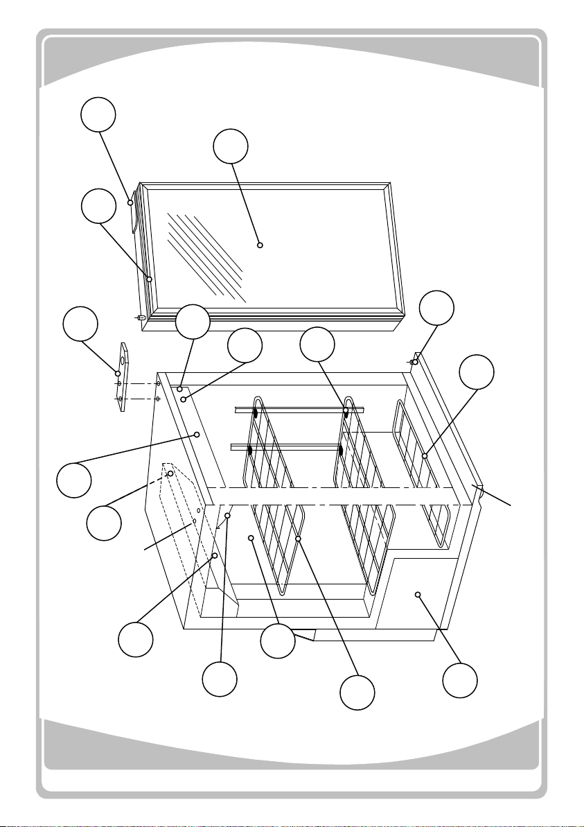
To Order Spares
"Find out the 'Diagram Number' of the spare(s)
wanted from the exploded diagram below.
"Refer to the parts Identification list (right) and find
the Description' of the spare(s).
"Find out the 'Serial Number' & 'Variant Number' of
your unit. These are shown on the serial label (a
metallic label located on the inside left wall of the
cabinet) and repeated on the front of this guide.
"Telephone our Sales Department on 01666 502641
with this information.
Spares Policy
The recommended spares for this unit are indicated in the
diagram below. These parts will be made available for a
period not less than five years after a machine has ceased to
be produced or a change has been introduced. Where a
change of part results in a lack of interchangeability, the old
part will continue to be available for five years. Where a
change of part or assembly of parts retains
interchangeability, the company reserves the right to supply
the new part or assembly only.
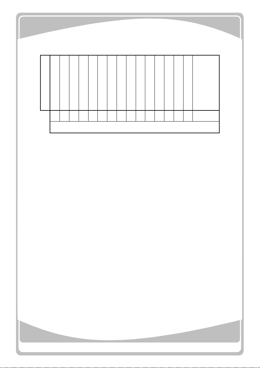
Description
1 Door seal
2 Evaporator Fan
3 Light Tube
4 Thermostat
5 Lamp Starter
6 Door handle
7 Evaporator
8 Light Diffuser
9 Shelf clip
10 Door bush
11 Door black metal Right
12 Hinge plate
13 Shelf
14 Light Switch
15 Bottom Shelf
Diagram Number
16 Condenser & Fan,
Compressor,
Condensate Pot,
Drier, Choke
06
16
13
8
7
2
4
12
16
3
10
5
14
9
11
Blanking
Plugs
Left Hand Hinge Point
Standard Hinge Point
Top
Hinge
Plate
15 Not all Models

07
Wiring Diagram Popular & Premier single units
Compressor
Evaporator Fan
Cabinet base earth stud (P.E.)
Condenser Fan
Thermostat
Light switch
Fluorescent light tube
Mains lead
Choke
Starter
Drawing Not to scale
Wires drawn green are
green with yellow tracer
Wires drawn grey are
actually white
Green Yellow
Blue
Blue
Blue
Red
Red
Brown
Brown Brown
Brown
Yellow
Yellow
Yellow Yellow
Orange
Black
Black
Orange
Yellow
Yellow
WhiteWhite
Thermostat probe
Green Yellow
Red
Blue
Brown
Brown
Green Yellow
Green
Yellow
L
N
Blue
Red
Blue
Brown
Blue
Yell
Blue
Brown x3
Red
Blue
Brown
Blue

08
Wiring Diagram Ecochill single units
Evaporator Fan
Cabinet base earth stud (P.E.)
Condenser Fan
Thermostat
Light switch
Fluorescent light tube
Mains lead
Choke
Starter
Drawing Not to scale
Wires drawn green are
green with yellow tracer
Wires drawn grey are
actually white
Blue
Blue
Red
Brown
Brown Brown
Brown
Yellow
Yellow
Yellow Yellow
Orange
Black
Black
Orange
Yellow
Yellow
WhiteWhite
Thermostat probe
Green Yellow
Red Red
Blue
Brown
Brown
Blue
Brown
Green Yellow
Green
Yellow
L
N
Blue
Brown
Blue
Yell
Blue
Brown x3
Red
Blue
Brown
Blue
Compressor
Compressor Speed Controller
Relay

09
Notes

10
Notes
Autonumis Ltd, Cirencester Rd,
Tetbury, Gloucestershire.
GL8 8SA United Kingdom
Tel +44 (0) 1666 502641
Fax +44 (0) 1666 504397
www.autonumis.com

Table of contents


