AvantaPure 269 User manual

Models: 269 Counter-Current Conditioner
Operations Manual

2 Table of Contents
Rev C
Table of Contents
How To Use This Manual 3
General Warnings And Safety Information 4
System Operation Cycle Functions 5
Equipment Installation 7
Valve Layout 7
Control Layout 8
Location Selection 9
Water Line Connection 10
Drain Line 12
Regenerant Line Connection 13
Overflow Line Connection 14
Electrical Connection 16
Valve Camshaft (Green) 17
Disinfection Of Water Conditioners 18
AvantaPure Controller 20
Display Icons 21
Keypad — Buttons 22
Things You Might Need to Know 23
Programming Overview 24
Level I Programming 24
Level II Programming 26
Level III Programming 31
Placing Conditioner Into Operation 32
Performa Exploded View 35
Performa Parts List 36
Troubleshooting 37

How To Use This Manual 3
RevC
How To Use This Manual
This installation manualis designed toguide the installer through the
process of installing and starting conditioners featuring the AvantaPure
controllers.
This manualis a reference and will not include every system installation
situation. The person installing this equipment should have:
• Training in the AvantaPure controllers and Autotrol brand valves
• Knowledge of water conditioning and how to determine proper
control settings
• Basic plumbing skills
• The directional instructions "left" and“right" are determinedby looking
at the front of the unit.
Icons That Appear In This Manual
Introduction
Inspect the unit for damage or missing parts. Contact your supplier if any
discrepancies exist.
Left Side Right Side
WARNING: Failure to follow this instruction can result in personal
injuryor damage to the equipment.
NOTE: Thiswill make the process easierif followed.

4 General Warnings And Safety Information
Rev C
General Warnings And Safety Information
Electrical There are no user-serviceable parts in the AC adapter, motor, or controller.
In the event of a failure, these should be replaced.
• All electrical connections must be completed according to local codes.
• Use only the power AC adapter that is supplied.
• The power outlet must be grounded.
• To disconnect power, unplug the AC adapter from its power source.
Mechanical
• Do not use petroleum based lubricants such asvaseline, oils,or
hydrocarbon based lubricants. Use only100% silicone lubricants.
• All plastic connections should be hand tightened.Teflon tape may be
used on connections that do not use an O-ring seal. Donot use pliers
or pipe wrenches.
• All plumbing must be completed according to local codes.
• Soldering near the drain line shouldbe done before connectingthe
drainlineto the valve.Excessiveheat willcauseinteriordamageto the
valve.
• Observe drain line requirements.
• Do not use lead-based solder for sweat solder connections.
• The drain line mustbe a minimum of 1/2-inchdiameter. Use
3/4-inch pipe if the backwash flow rate is greater than 7 GPM
(26.5 Lpm) or the pipe length is greater than 20 feet (6 m).
• Do not supportthe weight of the system on the controlvalve fittings,
plumbing, or the bypass.
• It is not recommended to use sealants on the threads. Use Teflon*
tape on the threads of the 1-inch NPT elbow, the drain line
connections, and other NPT threads.
*Teflon is a trademark of E.I. duPont de Nemours.
General • Observe all warnings that appear in thismanual.
• Keepthe media tank in the upright position.Do not turnupside down
or drop. Turning the tank upside down will cause media to enter the
valve.
• Operating ambient temperature is between 34°F (1°C) and 120°F
(49°C).
• Operating water temperature is between 34°F (1°F) and 100°F (38°C).

System Operation Cycle Functions 5
RevC
• Working water pressure range is 20 to 120 psi (1.38 to 8.27 bar).In
Canada the acceptable working waterpressure range is20 to 100 psi
(1.38 to 6.89 bar).
• Use only regenerant salts designed forwater softening. Do not use ice
melting, block, or rock salts.
• Follow state andlocal codes for water testing.Do notuse waterthat is
microbiologically unsafe or of unknown quality.
• When filling media tank, do not open water valve completely. Filltank
slowly to prevent media from exiting the tank.
• When installing the water connection (bypass or manifold) connect to
the plumbing system first. Allow heated parts to cool and cemented
parts to set before installing any plastic parts. Do not get primer or
solvent on O-rings, nuts, or the valve.
System Operation Cycle Functions
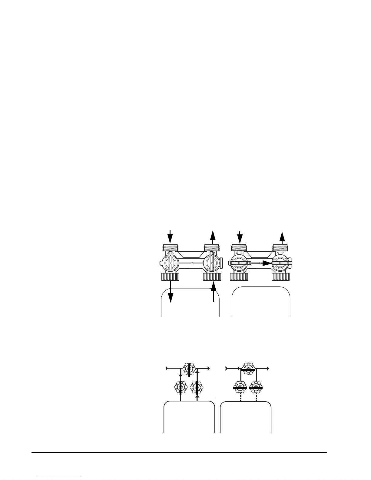
1. Service (Downflow)
Untreated water isdirected down through the resin bed and up
through the riser tube. The water is conditioned as it passes through
the resin bed.
2. Brine Refill
Water is directed down through the resin bed to the regenerant tank
at a controlled rate, to create brine for the nextregeneration.
3. Brine Preparation
The refill water is allowed to dissolve the salt and prepare brine.
4. Brine/Slow Rinse (Upflow)
The control directs water through the brine injector and brine is drawn
from the regenerant tank. The brine is then directed down the riser
tube up through the resin bed and up to the drain.The hardness ions
are displacedby sodium ions and are sent to the drain. The resin is
regenerated during thebrine cycle. Brine drawis completed when the
air check closes.
5. Repressurized Cycle (Hard Water Bypass Flapper Open)
This cycle allows the airand waterto hydraulically balancein the
valve before continuing the regeneration.
6. Backwash (Upflow)
The flow of water is reversed by the control valve and directed down
the riser tube and up through the resin bed. During the backwash
cycle,the bed is expandedand debris is flushed to the drain.
7. Fast Rinse (Downflow)
The control directs water down through the resin bed and up through
the risertube to the drain. Any remaining brine residual is rinsedfrom
the resin bed.

6 System Operation Cycle Functions
Rev C
Cycle Water Flows
BACKWASH
SERVICE
FAST RINSEREPRESSURIZE
BRINE/SLOW RINSE
From Regenerant
Tank
To Regenerant
Tank
BRINE REFILL BRINE PREP

Equipment Installation 7
RevC
Equipment Installation
Valve Layout
Refill Controller
Regenerant Tube Connection
Injector and cap
Valve Discs
Outlet
Drain
Inlet Backwash Injector Screen
Camshaft
Drain Control Filter
Control Module
Mount
One Piece Valve
Disc Spring
Motor
Optical Sensor

8 Control Layout
Rev C
Control Layout
AvantaPure Controller
LBS
PM
MIN
KG
x100
LCD Display
Manual Regen Button
Down Button
Set Button Up Button
For Future Use
Turbine Input or Dry Contact Signal Input
Main Motor &
Optical Sensor
Connection
AC Adapter
(low voltage)
Input
Chlorine Generator Outlet

Location Selection 9
RevC
Location Selection
Location of a water treatment system is important. The following
conditions are required:
• Level platform or floor
• Room to access equipment for maintenance and adding regenerant
(salt) to tank.
• Ambient temperatures over 34°F (1°C) and below 120°F (49°C).
• Water pressure below 120 psi (8.27 bar) and above 20 psi
(1.4 bar).
• In Canada the water pressure must be below 100 psi (6.89 bar).
• Constant electrical supply to operate the controller.
• Total minimum pipe run to water heater of ten feet (three meters) to
prevent backup of hot water into system.
• Local drain for discharge as close as possible.
• Water line connections with shutoff or bypass valves.
• Must meet anylocal and state codes for site of installation.
• Valve is designed for minor plumbing misalignments. Do not support
weight of system on the plumbing.
• Be sure all soldered pipes are fully cooled before attaching plastic
valve to the plumbing.
Outdoor Locations
When the water conditioning system is installed outdoors, several items
must be considered.
• Moisture — The valve and controllerare rated forNEMA 3locations.
Falling water should not affect performance.
The system is not designed to withstand extreme humidity or water
spray from below. Examples are:constant heavy mist, near corrosive
environment, upwards spray from sprinkler.
• Direct Sunlight — The materials used will fade or discolor over timein
direct sunlight. The integrity of the materials will not degrade to cause
system failures.
If it is necessary to locate the conditioner in direct sunlight, a
protective outdoor cover (PN 1242287) over the valve and controller is
necessary. A valve skirt (PN 1242286) that provides further protection
is available.
• Temperature — Extreme hotor cold temperatureswill cause damage
to the valve or controller.
Freezingtemperatureswillfreezethe waterinthevalve.Thiswillcause
physical damage to the internal parts as wellas the plumbing.
High temperatures will affect the controller. The display may become
unreadable but the controller should continue to function. When the
temperature drops down into normal operating limits the display will

10 Water Line Connection
Rev C
return to normal. A protective cover should assistwith high
temperature applications.
• Insects — The controller andvalve have been designedto keep allbut
the smallest insects out of the critical areas. Any holes in the top plate
can be covered with a metal foil ductwork tape. The top cover should
be installed securely in place.
• Wind — The cover is designed to withstand a 30 mph
(48 Kph) wind when properly installed on the valve.
Water Line Connection
A bypass valve system should be installed on allwater conditioning
systems. Bypass valves isolate the conditioner from the water system and
allow unconditioned water to be used. Service or routinemaintenance
proceduresmay alsorequirethat thesystem isbypassed.Theillustrations
below show the two common bypass methods.
Figure 1
Autotrol Series 1265
bypass for use with
Performa
Figure 2
TypicalGlobeValveBypass
System
Normal Operation In Bypass
B
Y
P
A
S
S
B
Y
P
A
S
S
B
Y
P
A
S
S
B
Y
P
A
S
S
Water
Conditioner
In Out
Water
Conditioner
In Out
Water Water
Cdii
Normal Operation In Bypass
Water
Conditioner Water
Conditioner

Water Line Connection 11
RevC
WARNING: The inlet water must be connected to the inlet port of the
valve. When replacing non-Autotrol valves, the inlet and outlet may be
reversed. It is also possible for the plumbing to be installed in an
opposite order.
Do not solder pipes with lead-based solder.
WARNING: Do not use tools to tighten plastic fittings. Over time,
stressmay break the connections. When the 1265 bypass valve is used,
onlyhand tighten the nuts.
WARNING: Do not use petroleum greaseon gasketswhen connecting
bypass plumbing. Use only 100% silicone grease products when
installing any Autotrol brand valve. Non-silicone grease may cause
plastic components to fail over time.
WARNING: Several tube adapters are available to connectthevalve
to the water plumbing. See PartsList.

12 Drain Line
Rev C
Drain Line
Drain Line Connection
1. The unitshould be above and not more than 20 feet (6.1 m) from the
drain.Use anappropriate adapter fitting to connect 1/2-inch (1.3 cm)
plastic tubing to the drain line connection of the control valve.
2. If the backwash flow rate exceeds 5 gpm (22.7 Lpm) or if the unit is
located 20-40 feet (6.1-12.2 m) from drain, use 3/4-inch (1.9 cm)
tubing.Use appropriate fittingsto connect the 3/4-inch tubing to the
3/4-inch NPT drain connection on valve.
3. The drain line may be elevated up to 6 feet (1.8 m) providing the run
does not exceed 15 feet (4.6 m) and water pressure at the conditioner
is not less than 40 psi (2.76 bar). Elevation can increase by 2 feet (61
cm) foreach additional 10 psi (.69 bar) of water pressure at the drain
connector.
4. Wherethe drain line is elevated but empties into a drain below the
level of the control valve, form a7-inch (18-cm) loop at the far end of
the line so that the bottom of the loop is level with the drain line
connection. This will provide an adequate siphon trap.
Where the drain empties intoan overhead sewer line, a sink-type trap
must be used.
Secure the end of the drain line to prevent it from moving.
Figure 3
Drain Line Connection
NOTE: Standardcommercialpractices are expressed here. Local
codes may require changes to the following suggestions. Check with
local authorities before installing a system.
Right Way
Air Gap
Drain
WARNING: Never insert drain line directly into a drain, sewer line or
trap (Figure 3).Always allow an air gap between the drain line and the
wastewater to prevent the possibility of sewage being
back-siphoned into the conditioner.

Regenerant Line Connection 13
RevC
Regenerant Line Connection
The regenerant line from the tank connects to the valve. Make the
connections and hand tighten. Be sure thatthe regenerantline is secure
and free from air leaks.Evena smallleakmay cause the regenerant lineto
drainout, and the conditionerwillnot draw regenerantfrom the tank. This
may also introduce air into the valve causing problems with valve
operation.
Ensure that pipe sealant (Teflon* tape) is applied to the 3/8-inch NPT
regenerant line connection.
Figure 4 RegenerantLine
Connection
*Teflon is a trademark of E.I. duPont de Nemours.
Regenerant Line Connection

14 Overflow Line Connection
Rev C
Overflow Line Connection
In the event of a malfunction, the regenerant TANK OVERFLOW will direct
“overflow” to the drain instead of spilling on thefloor. This fitting should be
on the side of the cabinet or regenerant tank. Most tank manufacturers
include a post for the tank overflow connector.
To connect the overflow line, locate hole on side of tank. Insertoverflow
fitting into tank and tighten withplastic thumb nut and gasket as shown
(Figure 5). Attach length of 1/2-inch (1.3-cm) I.D. tubing (not supplied) to
fitting and run to drain. Do not elevate overflow line higher than overflow
fitting.
Do not tie into drain line of controlunit. Overflow line mustbe a direct,
separate line from overflow fitting to drain, sewer or tub. Allow an air gap
as per drain lineinstructions.
Figure 5
Overflow Line Connection
Overflow Fitting
Drain Tubing
AirGap
Drain
Secure hose in place

Overflow Line Connection 15
RevC
Figure 6
Regenerant Tank Check Valve*
* Furnished as an option from system manufacturer.

16 Electrical Connection
Rev C
Electrical Connection
All controllers operate on 12-volt alternating current power supply.This
requires use of the GE WaterTechnologies supplied AC adapter. A variety
of AC adapters are available for different applications. These AC adapters
are available from your supplier. They include:
120 VAC AC Adapters
Make sure power source matches the rating printed on the AC adapter.
Controller Location
The controllers are designedto be mounted on the valve or attached to a
flat surface. Installations that do not provide easy access to the valve can
have the controller mounted for remote operation.
A remote mount connection, PN 1256257, is available for the AvantaPure
controller.
AC Adapter Input
Voltage Application Part Number
Standard wall-mount
AC adapter 120V60Hz Standard indoor
application 1000811
Outdoor rated AC
adapter 120V 60Hz UL listed for
outdoor
installations
1235448
NOTE: The power source should be constant. Be certainthe AC
adapter is not on a switched outlet. Power interruptions longer than 8
hours may cause thecontroller to lose the timeand day settings. When
power is restored, the day and time settings must then be re-entered.

Valve Camshaft (Green) 17
RevC
Valve Camshaft (Green)
The front end of thecamshaft has an indicator cup. The cup has slots in
the outerperiphery and numbers on the inside face (Figure 7).
The numbers can be seen with the cover off, from the front over thetop of
the controller. The numberat thetop indicates which regenerationcycle is
currently in progress.
Figure 7
Camshaft Front End for
269 Valve Bodies
The corresponding slot for the number is positioned at the optical sensor
which is approximately 90 degrees out of phase.
Regeneration Cycle Indicators
0 = Treated Water - normal operation mode
1=BrineRefill
2=BrinePrep
3 = Brine Draw / Slow Rinse Cycle
*4 = Holiday
*5 = Brine Empty / Slow Rinse
6, 7= System Pause
8 = Backwash Cycle
9=FastRinseCycle
*Cycles are skipped unless "Holiday Mode" is enabled.
Treated Water Slot
Treated Water Indicator
(normal operation)

18 Disinfection Of Water Conditioners
Rev C
Valve Disc Operation
Figure 8 - Performa Valve
Disinfection Of Water Conditioners
The materials of construction of the modern water conditioner will not
support bacterial growth, nor will these materials contaminate a water
supply. Duringnormal use,a conditioner may become fouledwith organic
matter, or in some cases with bacteria from the water supply. This may
result in an off-taste or odor in the water.
Some conditioners may need to be disinfected after installation and some
conditioners will require periodic disinfection during their normal life.
Depending upon the conditionsofuse, the style of conditioner,the type of
ion exchanger, and the disinfectant available, a choice can be made
among the following methods.
Sodium or Calcium Hypochlorite
Application
These materials are satisfactory for use with polystyrene resins, synthetic
gel zeolite, greensand and bentonites.
5.25% Sodium Hypochlorite
These solutions are available under trade names such as Clorox*. If
strongersolutions are used, such as those sold for commercial laundries,
adjust the dosage accordingly.
1. Dosage
A. Polystyrene resin; 1.2 fluid ounce (35.5mL) per cubic foot.
B. Non-resinous exchangers; 0.8 fluid ounce (23.7 mL) per cubic foot.
2. Brine tank conditioners
A. Backwash the conditioner and add the required amount of
hypochlorite solution to the well ofthe regenerant tank. The
regenerant tank shouldhave water init to permit the solutionto be
carried into the conditioner.
B. Proceed with the normal regeneration.
*Clorox is a trademark of the Clorox Company.
1 Regenerant Valve
2 Bypass Valve
3 Inlet Valve
4 Outlet Valve
5 Refill Valve
7 Backwash Drain Valves
6 Rinse Drain

Disinfection Of Water Conditioners 19
RevC
Calcium Hypochlorite
Calcium hypochlorite, 70% available chlorine, is available in several forms
including tablets and granules. Thesesolid materials may be used directly
without dissolving before use.
1. Dosage
A. Two grains (approximately 0.1 ounce[3 mL]) per cubic foot.
2. Regenerant tank conditioners
A. Backwash the conditioner and add the required amount of
hypochloritetothewelloftheregeneranttank.Theregeneranttank
should havewater in it to permit thechlorine solution to be carried
into the conditioner.
B. Proceed with the normal regeneration.

20 AvantaPure Controller
Rev C
AvantaPure Controller
Power Loss Memory Retention
The controllers feature battery-free time and date retention duringthe
loss of power. This is designed to last a minimum of 8 hours depending on
the installation. The controller will continue to keep time and day in
dynamic memory while there isno AC power.
The controllerwillnottrack waterusage on volumetric demand controlsin
the event of a power failure.
All programmed parameters are stored in the static memory and will not
be lost in the event of a power failure. These settings are maintained
separately from the time and day settings.
Motor The controller uses a standard 12-volt AC motor that works with either 50
Hz or 60 Hz.The same motor is used worldwide and does not need to be
changed for different power conditions.
Controller Memory
Information entered or calculated by the controller is stored in two
different ways.
A static memory will store:
Model number
Regenerant setting
Time of regeneration
Days between regeneration
Filter mode
A dynamic memory with 8 hour retention will store:
Current day of week
Running clock
Variable Reserve Function The metered-demand volumetric controllers are designed with a variable
reserve feature. This feature automatically adjusts the reserve to the end-
user’s water usage schedule.
A variable reserve saves salt and water by only regenerating when
absolutely necessary, and ensures enough soft water for typical
high-water usage days.
Each day of regeneration the controller reviews the last four weeks of
water usageforthe same day of the week to determine if the remaining
capacity is adequatefor the next day of the week. If not, it will initiate an
automatic regeneration.
NOTE: Water flowto thevalvecanbeturned onorbypassedwhenthe
controller is powered up for the first time.
Table of contents