Superior Electric STABILINE CRA141S010 User manual

213709-264 Rev. A
EC99741
INSTRUCTIONS
for
STABILINE ®
Power Conditioner
CRA141S010
Single Phase
480 Volt Input
120 Volt Output
Single Control
Superior Electric reserves the right to make engineering changes on all its products. Such refinements may affect
information given in the instructions. Therefore, USE ONLY THE INSTRUCTIONS THAT ARE PACKED WITH THE
PRODUCT.
WARNING: High voltages are present inside this unit during operation. Do not operate this unit unless all
covers are in place. Installation and servicing should only be done by qualified personnel.

2

3
TABLE OF CONTENTS
SECTION PAGE
SECTION PAGE
1.0 INSPECTION............................................... 3
1.1 UNPACKING........................................ 3
2.0 DESCRIPTION ............................................ 3
2.1 GENERAL............................................ 3
2.2 MODEL NUMBER ASSIGNED ............. 3
2.3 STANDARD MODEL NUMBER SYSTEM 4
2.4 THEORY OF OPERATION................... 5
3.0 INSTALLATION...........................................
3.1 TRANSPORTING THE REGULATOR .. 5
3.2 MECHANICAL INSTALLATION............ 5
3.3 ELECTRICAL INSTALLATION ............. 5
4.0 START UP................................................... 5
5.0 OPERATION ............................................... 6
5.1 CONTROL MODULE ASSEMBLY........ 6
5.2 SETTING OUTPUT VOLTAGE AND
SENSITIVITY POTENTIOMETERS...... 6
5.3 REMOTE SENSING ............................ 6
6.0 OPTIONS.................................................... 7
6.1 NON DESIGNATED OPTIONS............ 7
6.2 MODEL No. SPECIFIED OPTIONS..... 7
7.0 MAINTENANCE.......................................... 9
8.0 TROUBLESHOOTING................................ 9
9.0 RATING...................................................... 11
9.1 POWER RATINGS .............................. 11
9.2 GENERAL SPECIFICATIONS ............. 12
10.0 REPLACEMENT PARTS ............................ 13
10.1 ORDERING......................................... 13
10.2 CONTROL MODULE ASSEMBLY ....... 13
10.3 POWER COMPONENTS..................... 13
10.4 REPLACEMENT BRUSH ASSEMBLY. 13
11.0 SCHEMATIC............................................... 14
12.0 FLOOR MOUNT DIMENSIONS .................. 15
1.0. INSPECTION
1.1. UNPACKING
When unpacking the unit, examine it carefully for any
shipping damage. The "Damage and Shortage"
instructions packed with the unit outlines the procedure
to follow if any parts are missing or damaged.
2.0. DESCRIPTION
2.1. GENERAL
CRA141S Series STABILINE®Power Conditioners are
fast acting, fully isolated power conditioners that provide
filtered and regulated power for sensitive loads. These
power conditioners are designed for a 480 volt, single
phase input and a 120 volt, single phase output. These
voltage conditioners incorporate an analog electronic
control section and a power section consisting of one or
more motor driven POWERSTAT®Variable
Transformers. The units can be equipped with a
number of standard options. Refer to the CRA model
numbering system in the next section for more details.
See the rating sections and unit nameplate for complete
specifications.
Advantages of all CRA Series power conditioners
include high efficiency (97% typical), high overload
capacity and low impedance. These power conditioners
are insensitive to the magnitude and power factor of the
load, and have little to no effect on system power factor.
This means these units can be used with any type load.
2.2. MODEL NUMBER ASSIGNED
The model number for each CRA Series Power
Conditioner identifies the various characteristics of that
specific unit. Refer to the Standard Model Number
System table to determine a unit’s characteristics and
options.

4
2.3. STANDARD MODEL NUMBER SYSTEM
The model number for each CRA Series conditioning voltage regulator identifies the various characteristics of that
specific unit. The following table explains the meaning of each character in a standard model number.
Typical Model Number →
CRA
1 2 W 2 H S 017
- CB D M T 3 6 7
CRA Conditioning Regulator, Analog
1 Single Phase
2 Two Phase
3 Three Phase
1 Nominal Voltage 120-127 (100)
2 Nominal Voltage 208 X 220-230-240 (277)
4 Nominal Voltage 380-400-415 X 480
6 Nominal Voltage 480 X 600
blank Standard Range (-20 to + 10% typical)
W Wide Range (-30 to +15% typical)
1 Nominal Voltage 120-127 (100)
2 Nominal Voltage 208 X 220-230-240 (277)
4 Nominal Voltage 380-400-415 X 480
6 Nominal Voltage 480 X 600
Blank KVA Rated for Non & Boost
H KVA Rated for Boost mode
S Single Control
D Double Control
T Triple Control
NNN Load KVA Rating
CB Input Circuit Breaker (with no trip coil)
CS Input Circuit Breaker with 120vac Shunt Trip
CR Input Circuit Breaker with 120vac Under voltage Trip Release
D Delayed Output
M Manual Bypass Switch
T Tropicalization Treatment
0 No Meter Options
(3)
1 Ammeter(s)
2 Frequency Meter w/ Alarm Contacts
3 Both 1 & 2 above
0 No Alarm Circuit Options
(3)
4 Input Voltage Range Alarm(s)
5 Phase loss/Phase reversal Alarm
6 Both 4 & 5 above
0 No Miscellaneous Options
(3)
7 Manual Raise / Lower Switch(s)
8 Soft Start
9 Both 7 & 8 above
(1) Base model numbers (no options) as shown in catalog include the characters up to the hyphen (-).
(2) For lettered options not selected the letters and spaces are omitted from the model number.
(3) The last three numbers in the model number are all used unless all three are zero then they are omitted.

5
2.4. THEORY OF OPERATION
CRA Series STABILINE®Power Conditioners maintain
a constant regulated output AC voltage by simulating an
infinite number of taps, between two real taps, on the
input of an isolation transformer. This is accomplished
automatically by adjusting a POWERSTAT®Variable
Transformers connected between a boost tap and a
buck tap of the isolation transformer. Using the brush of
the POWERSTAT as the input point, the “input tap” and
thus the output voltage can be controlled with great
accuracy.
A solid-state control unit detects the output voltage and
continually compares it with output and accuracy
settings selected by the user. If the voltage is out of
specifications, the control unit drives the POWERSTAT
variable transformer, by means of a synchronous motor,
to the required new position.
These units attenuate transverse-mode (line-to-line)
transients by 60 dB (1,000 to 1). This is accomplished
with a low-pass filter that attenuates regardless of
where on the sine wave or in which direction the
transient is applied, and does not rely on an absolute
amplitude before attenuation occurs. Peak clipping
devices are also included to assist in handling larger
transients.
Voltage transformation and common-mode (line and
neutral to ground) noise attenuation of 120 dB
(1,000,000 to 1) is provided by the double shielded
isolation transformer. Shield 1 in the isolation
transformer should be connected to the secondary
ground and increases the common mode noise
rejection. Shield 2 is between the primary and the
grounded shield, need not be connected, and is used to
reduce the conversion of common mode input noise to
normal mode output noise.
3.0. INSTALLATION
3.1. TRANSPORTING THE POWER CONDITIONER
Due to its weight and size, proper lifting procedures
must be followed when transporting the unit and moving
it into the location where it is to be installed.
The proper method for moving these units is to place a
forklift under the base. A heavy frame is provided in this
area to allow lifting the unit in this manner without
damage. The 26 inch (559 mm) wide enclosures can
also be lifted by removing the top cover and using the
lifting eyes provided in the sides of the cabinet.
3.2. MECHANICAL INSTALLATION
The power conditioner is designed for floor mounting.
When mounting the unit, allow a minimum clearance of
4 inches (100 mm) behind the unit for proper ventilation.
All internal components and wiring connections are
accessible through the front panels. A 3 foot (1000 mm)
area in front of the unit should be kept clear for
installation and service.
3.3. ELECTRICAL INSTALLATION
All CRA Series Power Conditioners are designed to be
hard-wired to the input power and the load using copper
wire. When these units increase low input voltage to
give nominal output voltage, the input current is
substantially higher than the nominal input current.
Maximum rated input and output currents for each unit
are given in the enclosed rating charts. Select a wire
size that is adequate to carry the maximum rated
current as specified by local and national code
requirements.
The front panel(s) of the power conditioner must be
removed to allow access to the input and load
terminals. To remove a panel, use a screwdriver to
release the ¼ turn fasteners, which hold the front panel
in place, and lift the panel off the base. A full range of
knockouts is provided in the base and the rear panel of
the unit for wire entry and exit.
The location of the power connections varies depending
on the options provided. On units with an input circuit
breaker, input connections are made directly to the
circuit breaker. The input connection for other options or
no options varies. Input connections are labeled L1
and L2. Load connections are made directly to the
isolation transformer on units without any options.
These output connections are labeled X1 and X2.
Units that have output options (ex. ammeters) will not
have the output connections on the isolation
transformer. These output connections are labeled
T1 and T2.
The outputs of the CRA Series Power Conditioners are
floating (not referenced grounded). If the unit’s output is
to be grounded the installer must make the ground
connection to the proper terminal.
For optimum common mode noise attenuation, it is
usually best to ground the shield 1 connection and allow
shield 2 to float. The unit is shipped with shield 1
connected to X1. If the installation’s ground is on X1
this is fine. If the installation requires the ground on X2,
the shield 1 connection should also be moved from X1
to X2.
The safety ground terminals are a ground stud on the
cabinet wall, or a lug on the base, and must be
connected to a suitable earth ground to reduce the
chance of electrical shock.
4.0. START UP
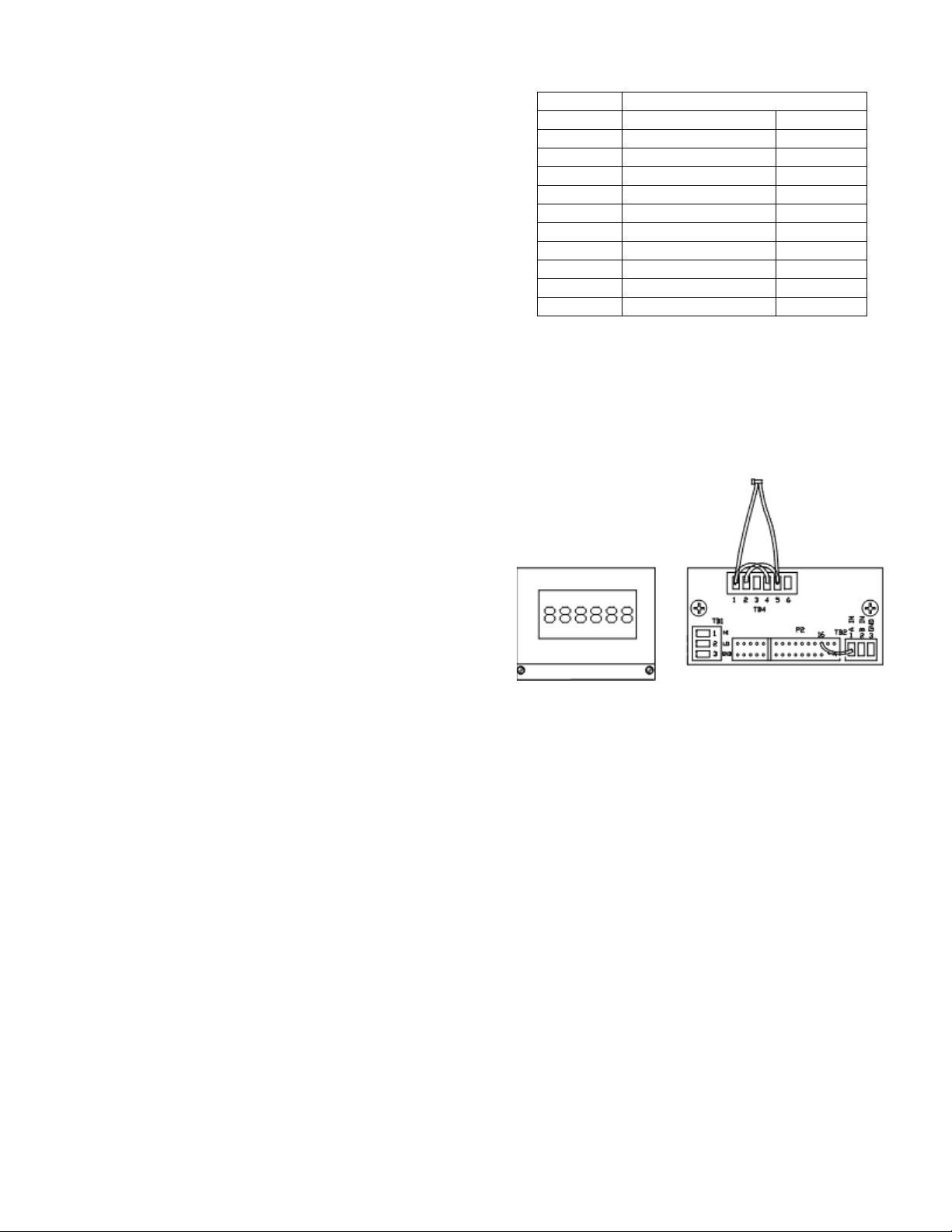
Set the Output Voltage Range toggle switch on each
control module to the 120 volt position to turn on the
control. The Output Voltage Adjustment and the
Sensitivity potentiometers are set at the factory for a
nominal output voltage and approximately 2% accuracy,
and should not be readjusted until the power
conditioner is initially energized.

6
After all input and output connections are completed
and checked, place the front panel(s) in position and
tighten the fasteners.
Energize the regulator power source and, if provided,
place the unit’s circuit breaker in the "ON" position. The
voltmeter should indicate the output voltage (approx.
120 volts), and the POWER pilot lamps and the
CONTROL pilot lamps should be lit. This indicates the
voltage conditioner is operating properly.
5.0. OPERATION
5.1. CONTROL MODULE ASSEMBLY
5.1.1. General
The control modules contain the circuitry that sense the
output voltage and determine if correction is needed.
When correction is required this circuit sends a raise or
lower signal to the motor driven variable transformers.
To eliminate unauthorized tampering of the control
module the items marked (♦) below are located behind
the front panel.
5.1.2. Power Pilot Lamps (A1-LP1)
The POWER lamp on each control assembly lights
when power is present for the motor on that phase. This
indicates the voltage regulator is energized.
5.1.3. Control Pilot Lamps (A1-LP2)
The CONTROL lamp lights when the control assembly
sense voltage for that phase is energized. The control
sense voltage must be energized for automatic
correction of voltage changes to occur.
5.1.4. Analog Voltmeters (A1-M1)
These meters show the output voltage that is sensed
and controlled by the control module. For the CRA141
series units this is the 120 volt output.
5.1.5. Output Voltage Range Toggle Switches
(A1-S1)♦
With these switches in the OFF position, the control
sense voltage for that phase is disconnected and the
control pilot lamp is not illuminated. In this position
automatic correction for voltage changes will not take
place and any change in input voltage will be reflected
in output voltage. The switch should be placed in either
the “120” position to energize the control assembly
sense voltage and allow automatic correction of voltage
changes.
5.1.6. Output Voltage Potentiometers ♦
This potentiometer sets the output voltage (X1-X2). The
adjustment range is approximately ± 10% of nominal
output voltage.
5.1.7. Sensitivity Potentiometers ♦
This potentiometer adjusts the output voltage accuracy
and therefore set how much the output voltage will
change before the unit will correct. The accuracy is
increase with clockwise rotation of the SENSITIVITY
potentiometer.
5.1.8. Fuses (A1-F1 to A1-F4) ♦
The four fuses located on the control module protect the
motor and sense power lines. If the POWER or
CONTROL lights are not lit, and all control settings are
proper, check for a blown fuse.
5.2. SETTING OUTPUT VOLTAGE AND
SENSITIVITY POTENTIOMETERS
Normally, the CRA Series power conditioner should not
be operated without the front panel(s) of the cabinet in
place. However, during the initial operation the front
panels can be removed to allow setting the OUTPUT
VOLTAGE and SENSITIVITY potentiometers.
5.2.1. Energize Regulator
On units equipped with a manual bypass switch ensure
it is in the regulator position. Energize the conditioner’s
power source and place the input circuit breaker, if so
equipped, in the "ON" position. The pilot lamps should
light, indicating that the CRA Series Power Conditioner
is energized and that the control unit is on. If necessary,
move the OUTPUT VOLTAGE RANGE switch to the
desired nominal output voltage position. The voltmeter
will indicate the output voltages.
5.2.2. Set Output
To adjust the output voltage on any phase, turn the
OUTPUT VOLTAGE potentiometer clockwise to
increase or counterclockwise to decrease the output
voltage, as indicated on the voltmeter for that phase.
5.2.3. Set Sensitivity
The sensitivity must be adjusted if the voltage regulator
hunts (motor driven variable transformer section of the
voltage conditioner continually cycles back and forth) or
if the regulator allows too great a change from the set
voltage before correction occurs.
Turning the SENSITIVITY control clockwise increases
the sensitivity to maximum (± 0.75% to 1% output
voltage accuracy). For maximum sensitivity, turn the
SENSITIVITY control clockwise to the point where the
POWERSTAT begins to hunt. Turn the control
counterclockwise (CCW) until the hunting stops. Turn
the control an additional 1/8 turn CCW.
5.2.4. Close
Replace the front cover(s).
5.3. REMOTE SENSING
Normally, these voltage conditioners sense and
regulate the voltage at the output terminals, In some
cases better control can be obtained by regulating the
voltage at another point, such as at the end of long lines
between the regulator and the load. This is known as
remote sensing.

7
If remote sensing is desired, move the wire connected
to terminal 6 to terminal 7 and the wire connected to
terminal 8 to terminal 9 on the control module terminal
panel. This will disconnect the control module sense
terminals from the output terminals of the regulator.
Connect remote sensing wires to terminals 6 and 8 on
the control modules.
6.0. OPTIONS
6.1. NON DESIGNATED OPTIONS
6.1.1. Auxiliary Power Modules (A2)
These modules are provided on units where a 120 volt
AC source is required to operate internal circuitry. The
output voltage of these modules is on terminals 1 and 2
of the terminal strip. If there is no output on these
terminals check the two fuses mounted on the same
bracket. The output of the auxiliary power modules are
used to operate fans, trip or hold on circuit breakers,
and on any other applications where 120 volts is
required.
6.1.2. Fans (B2)
On larger units fans are provided to help efficiently
remove heat generated in the cabinet. An auxiliary
power module supplies the fan operating voltage. If the
fans do not operate insure the auxiliary power module
output voltage is present.
6.2. MODEL NUMBER SPECIFIED OPTIONS
6.2.1. Circuit Breaker (CB1)
An input circuit breaker provides short circuit and
overload protection for the CRA Series Power
Conditioners. Industrial circuit breakers with high
interrupting capacity are used. These breakers also
serve as an on/off switch for the regulator and any load
attached.
6.2.1.1. Shunt Trip
In units where the model number designates the circuit
breaker as “CS” the circuit breaker is equipped with a
shunt trip. A shunt trip causes the breaker to open when
voltage is applied to the shunt trip coil. The trip coil is
rated 120 volt, AC and is de-energized when the
breaker opens.
When alarm contact options and a circuit breaker trip
option are ordered together, the unit is furnished with
120 volt AC, auxiliary power module (A2) and the alarm
circuit contacts are wired to trip the input breaker. The
Shunt Trip Connections Diagram shows the typical
connections.
If you do not want the alarm contacts to trip the input
breaker, the unit can easily be re-configured to not trip
the breaker and to perform other control functions. The
120 volts supplied by the auxiliary power module to trip
the shunt coil can be replaced by an external source if
desired, but do not disconnect any other devices from
this source. A momentary push button switch (S4) is
provided to disable any alarm contacts from activating
the trip coil. This allows turn on of the system so alarm
options can reset. Hold switch in while turning on the
circuit breaker.
Shunt Trip Connections Diagram
6.2.2. Manual Bypass Switch (S3)
A two-position, non-load break, manual bypass switch
provides a nominal output voltage in the even of an
internal component failure. In the "REGULATOR"
position, the units regulating and transient suppression
components are active providing a conditioned output.
In the "BYPASS" position the regulating variable
transformer, motor power and transient suppression
circuits are disconnected from the isolation transformer.
The input power is connected to the nominal input tap
on the isolation transformer’s primary. This provides
nominal isolated voltage to the load. The neutral or
second input line, having no control components in
series, is not switched. The circuit breaker and isolation
transformer remain in line regardless of the bypass
switch position, since they are always needed. The
control unit’s voltmeter will continue to show the output
voltage, as long as the range switch is not in the off
position, but no correction is performed.
6.2.3. Ammeters (M1)
An analog ammeter displays load current for each
phase. Each meter indicates the load current within 2%
of the meters full range.

8
6.2.4. Frequency meter with alarm contacts (M2)
Frequency meter displays the source frequency and
provides alarm contacts for values outside the user's
settable limits. Lower and upper limit trip relays are
factory set at 45 Hz and 65 Hz respectively. If the
frequency becomes lower or higher than user selected
values, an output relay is energized. The relay is
equipped with a form “C ” normally open / normally
closed contact available for customer use.
If a circuit breaker with a trip coil is ordered with the
frequency meter, the system is configured to
automatically trip the breaker when a limit is exceeded.
6.2.4.1. Frequency Meter Instructions
The frequency meter owner’s manual is included with
the literature sent with the unit. If no user setting were
stored, pressing both RECALL buttons at the same time
can reinstate the stored factory setting.
The stored factory settings are shown in the table
below. To return stored setting to the factory default, tap
the ENTER key to go to the next feature then use SET
and ADVANCE keys to change the setting to those
shown. When the display shows Store tap the Enter key
to lock the setting into memory. To return to these
setting both RECALL keys must be depressed at the
same time.
Feature Setting
Func Freq
Scale A / SC 2.00000
Offset 000000.
Range FFFF.FF
Slope A Pos
Sp lo 000045
Sp hi 000065
Gate t 01.30
Conf 1 no setting required
Conf 2 no setting required
No store Store
A front and rear view of the frequency meter is shown
below with the N.O. alarm contacts in parallel. The
alarm contacts are connected to TB4 as follows:
1 – HI relay Com 4 - LO relay COM
2 – HI relay N.O. 5 - LO relay N.O.
3 – HI relay N.C. 6 - LO relay N.C.
Frequency Meter
6.2.5. Alarm Contact Ratings
Alarm circuit contacts provided with the Frequency Trip
Meter, Input Voltage Range Alarm and Phase Loss -
Phase Reversal options are rated 5 amps 240 volts AC.

9
7.0. MAINTENANCE
To ensure maximum life of the equipment, the following
should be part of an annual maintenance program.
Warning
De-energize unit before performing maintenance.
Voltages are present inside this unit which can
cause injury. Therefore, only personnel qualified to
service electrical equipment should perform
maintenance on this unit.
7.1. Vacuum the voltage conditioner inside and out to
remove accumulated dirt, which could lead to
overheating or insulation failure.
7.2. Tighten all electrical connections, particularly all
power wiring to, and in, the unit.
7.3. Inspect all variable transformer brushes and
commutators for signs of wear or pitting. Replace as
required. See diagram below.
Do not attempt to clean a commutator with an
abrasive such as sandpaper or a file. This will ruin
the soft precious metal plating on the commutator and
will shorten the life of the unit. It is normal for
commutators to become black due to carbon brush
tracking. If a commutator is to be cleaned, use
denatured alcohol and a soft cloth.
7.4. Inspect the variable transformer drive belts,
sprockets, gears, cams, etc. for signs of slippage or
wear and adjust as required.
7.5. Check the variable transformer radiator(s) (the
die cast part that holds the brush assembly) for signs of
slippage, and see if all brushes driven by the same
motor are aligned with each other. The alignment of the
radiator and brushes depends on the setscrews that
hold the variable transformer center tube(s) to the shaft
and the setscrews that hold the radiator to the center
tube. Adjust and tighten as needed.
7.6. Lubrication of the WHR Series voltage regulator
is not required since it has been lubricated at the factory
for its lifetime.
8.0. TROUBLESHOOTING
CRA Series Power Conditioner will provide long,
reliable service with little attention. Unless the unit is
overloaded, there is little likelihood of component
failure.
Warning
Voltages are present inside this unit which can
cause injury. Therefore, only personnel qualified to
service electrical equipment should perform
trouble-shooting procedures on this unit.
If the conditioner fails to operate correctly, the following
checks will help locate and correct the problem. Refer
to the schematic, rating chart and replacement parts list
for further information.
8.1. Check the load connected to the voltage
regulator to be sure the unit's output current rating is not
being exceeded.
8.2. See if the POWER pilot lamps are on. If a lamp is
not on, there is no power to the voltage regulator, or
fuses F1 & F2 (POWER LIGHT MOTOR) on that control
module are blown, or the lamp has burned out. Check
the POWER LIGHT MOTOR fuses (F1 and F2). Check
the power input to the unit, to be sure the voltage is
within the range specified for the selected output
voltage.
8.3. Check the output voltmeters. If a meter shows
zero output voltage, check the input line, control module
fuses F3 and F4 (CONTROL fuses), remote sense
wiring if applicable, and input connections. If so
equipped, check position of input circuit breaker and
manual bypass switch.
8.4. Check the CONTROL pilot lamps. If one is not lit,
check it's VOLTAGE RANGE switch to be sure it is on
and check for blown CONTROL fuses (F3 and F4). If
applicable, check the remote sense wiring.
8.5. If the motor hunts (cycles continuously), readjust
the SENSITIVITY control.
8.6. If a motor drives a POWERSTAT variable
transformer to one end of its travel, and the voltage
decreases when it should increase or increases when it
should decrease, check to see if the input and output
power connections to the voltage conditioner are
reversed. If applicable, check the remote sense wiring.
8.7. If the unit has been reworked or repaired, check
to see if the leads driving the motor have been
reversed. A1-TB1-2 and A1-TB1-3 provide the motor
power to lower and raise the motor with A1-TB1-1 being
the common for both AC voltages.
8.8. If the motor continues to hum or buzz after the
OUTPUT VOLTAGE RANGE switch is turned off, the
solid-state switch controlling the motor may be
defective. De-energize the input line to the voltage
regulator, and replace the control board.
8.9. If the motor has driven to one end or does not
drive at all, check to ensure the motor drive is

10
functioning correctly. Refer to the unit's schematic
diagram to complete the following steps:
De-energize the input line to the voltage regulator;
place the OUTPUT VOLTAGE RANGE switch in the
center (off) position, and remove POWER LIGHT-
MOTOR fuses F1 and F2 on each control module.
Apply 115 volts AC between terminals A1-TB1-1 and
A1-TB1-2 on the control module, or to the
corresponding terminals at the motor board terminal
strip (TB1). The motor should turn the variable
transformer counter clockwise (viewed from top) so as
to lower the output voltage until it reaches the end of its
travel, where the limit switch will prevent further rotation
in that direction.
Apply 115 volts between terminals A1-TB1-1 and
A1-TB1-3 should run the motor in the opposite direction
until a limit switch stops the motor at the end of travel.
If the motor operates successfully in this test the
problem may be with the control board.
8.10. Inspect the POWERSTAT Variable Transformer
brush(s) and commutator(s) for signs of wear or
damage. The brush assemblies on the variable
transformer section will not need replacement under
normal conditions. When excessive brush wear or
commutator damage occurs, it is usually the result of an
overload. If either condition exists, the POWERSTAT
Variable Transformer section or the brush must be
replaced or repaired. Check the load to be sure the
output current rating of the voltage conditioner is not
being exceeded.
Do not attempt to clean a commutator with an
abrasive such as sandpaper or a file. This will ruin
the soft precious metal plating on the commutator
surface and will shorten the life of the unit. It is normal
for commutators to become black due to carbon brush
tracking. If a commutator is to be cleaned, use
denatured alcohol and a soft cloth.
8.11. Check the variable transformer radiator(s) (the
die cast part that holds the brush assembly) for signs of
slippage, and see if all brushes driven by the same
motor are aligned with each other. The alignment of the
radiator and brushes depends on the setscrews that
hold the variable transformer center tube(s) to the shaft
and the setscrews that hold the radiator to the center
tube. Adjust and tighten as needed.

11
9.0. RATING
9.1. POWER RATINGS
INPUT:
VOLTAGE: 480 VOLTS
FREQUENCY: 60 Hz
CONNECTION: 1 Phase, 2 Wire, plus safety ground
RANGE: -20%, +10%
OUTPUT:
VOLTAGE: 120 VOLTS
CURRENT: 84 Amps Max.
CONNECTION: 1 Phase, 2 Wire

12
9.2. GENERAL SPECIFICATIONS
Electrical:
Output Accuracy Adjustable from ±1% to 3%
Load Capacity 100% rated continuous
200% rated 60 seconds
400% rated 3 seconds
600% rated 1 second
800% rated 0.5 second
1000% to 2500% 1/2 cycle inrush
Load Power Factor 0 lagging to 0 leading
Load Crest Factor 6 Max (I peak / I RMS)
Efficiency 97% typical, at full load
Heat Generated BTU (typical) = 106 x rated kVA
Harmonic Distortion Less than 1% added
Surge Withstand Capability 6000 volts per IEEE C62.41, location category B
Impedance 4% (typical)
Common-mode Attenuation 120 dB
Transverse-Mode Noise Attenuation 60 dB
Environmental:
Service Conditions Units are housed in NEMA 1 ventilated enclosures, intended for indoor use under usual
service conditions.
Temperature
Operating Average ambient temperature for any 24 hour period not to exceed 30°C (86°F), and
maximum temperature not to exceed 40°C (104°F). Average ambient temperature for any
24 hour period may be increased to 40°C (104°F),and the maximum temperature may be
increased to 50°C (122°F),if the load is decreased to 90%of standard rating. Minimum
temperature is 0°C (32°F).
Storage -40°C to +70°C (-40°F to +158°F)
Humidity (Operating and Storage)
Units without tropicalization 10 to 75% average relative humidity for any 7 day period, and maximum relative humidity
not to exceed 95% non-condensing.
Units with tropicalization 10 to 95% average relative humidity and maximum relative humidity not to exceed 95%
non-condensing.
Altitude
Operating Maximum Altitude Derating
6,600 Ft.(2,000 meters) No de-rating
10,000 Ft.(3,000 meters) load to 95%,ambient 30°C (86°F)
15,000 Ft.(4,500 meters) load to 90%,ambient 20°C (68°F)
Storage 50,000 Ft.(15,000 meters)max

13
10.0. REPLACEMENT PARTS
10.1. ORDERING
Because this manual covers a full series of units it is
impractical to provide a full list of replacement parts. To
order a part not listed in this manual, provide the unit
model number, serial number, and date code.
Reference the part by schematic reference symbol,
description and part number if available.
10.2. CONTROL MODULE ASSEMBLY
The same control modules are used throughout this
standard CRA Series STABILINE®Power Conditioners
and are shown below. Tropicalized units have a
similar control module but some of the parts are
specially treated and therefore have a different part
number.
FLOOR MOUNT CONTROL MODULE ASSEMBLY (A1)
Reference Symbol
Part Description
Part Number
A1 CONTROL MODULE 213243-010
A1-A1 CONTROL BOARD 227412-001
A1-F1,F2,F3,F4 FUSE, 1A, 600V
213274
-
001
A1-LP1,LP2 LIGHT, INDICATOR, GREEN 227571-001
A1-M1 VOLTMETER 212917-001
A1-S1
SWITCH, ROCKER ON/
-
/ON
227572
-
002
A1-T1 TRANSFORMER, POWER 227608-001
10.3. POWER COMPONENTS
The following parts are specific to each model number.
MODEL
NUMBER
T1 (EACH DECK)
POWERSTAT,
VARIABLE
TRANSFORMER
REPLACEMENT
BRUSH
ASSEMBLY
FOR T1
CRA141S010
150548
-
002
017702-004
10.4. REPLACEMENT BRUSH ASSEMBLY
Each POWERSTAT®Variable Transformer contains a durable brush assembly. These assemblies are designed to
reduce the need for attention or replacement; however, because these are moving parts that rely on contact friction
to operate properly, an annual inspection is suggested. Refer to the maintenance section of this manual for details.
Part number for a replacement brush assembly is listed in the table above.

14
11.0. SCHEMATIC (For reference only, use full size supplied with unit)

15
12.0. FLOOR MOUNT DIMENSIONS
Enclosures A through G
Note: All dimensions are inches [millimeters]

16
Enclosures A through G continues
Note: All dimensions are inches [millimeters]

17
Enclosures A through G continues
Note: All dimensions are inches [millimeters]

18
Available Coast-To-Coast and Internationally
Voltage Control Components
POWERSTAT
®
Variable Transformers
VOLT-PAC
®
Variable Transformers
LUXTROL
®
Lighting Controls
5-WAY
®
Binding Posts
SUPERCON
®
Electrical Connectors
Power Quality Solutions
STABILINE
®
Automatic Voltage Regulators
STABILINE
®
Transient Voltage Surge
Suppressors
STABILINE
®
Uninterruptible Power Supplies
STABILINE
®
Power Conditioners
Voltage Control Components are available worldwide
through an extensive Authorized Stocking Distributor
network. These Distributors offer literature, technical
assistance and a wide range of models off-the-shelf for
fastest possible delivery and service.
STABILINE Power Quality Solutions are available
worldwide through an extensive Authorized Distributor
and Reseller network, which offer literature, technical
assistance and a select range of models off-the-shelf
for fastest possible delivery and service.
In addition, Superior Electric Manufacturer’s Representatives are available to provide prompt attention to customer
needs. Call or fax for ordering and application information or for the address of the closest Manufacturer’s
Representative, Authorized Distributor or Reseller.
Telephone and Fax Numbers
Telephone 860-507-2025
Fax: 860-507-2050
Customer Service: 860-507-2025 Ext. 70782
Product Application 860-507-2025 Ext. 72058
Toll-Free (in U.S.A. and Canada only)
Telephone 1-800-787-3532
Fax: 1-800-821-1369
Customer Service: 1-800-787-3532 Ext. 70782
Product Application: 1-800-787-3532 Ext. 70058
1 Cowles Road • Plainville, CT 06062
www.superiorelectric.com
The right to make engineering refinements on all products is reserved. Dimensions and other details are subject to change.
© 17 NOV 2014
213709-264_1_A_CRA141S010 MNL.DOCX
17-Nov-14
An ISO9000
Registered Company
Table of contents
Popular AC Power Distribution manuals by other brands

ETA Systems
ETA Systems ETA-ECM20 Information sheet

Furman
Furman IT-20 II owner's manual

CTEK
CTEK Daycruiser User instructions and installation manual

B+K precision
B+K precision 9801 Programming manual

FRONIUS
FRONIUS TransSynergic 5000 Operating instructions & spare parts

Tripp Lite
Tripp Lite TLM626NS Specifications