Avantco 178Z1FHC User manual

Service Manual Service Manual
Commercial Top Mount Reach-In Freezer
- 1 -
Solid door: 178Z1FHC, 178Z1FWMS, 178Z2FHC, 178Z2FWMS
NOTICE
• This manual is for a certified service technician and should not be used by those who are not properly trained.
• This manual cannot cover all possible conditions that may occur and is not intended to be all encompassing.
• You should read this manual in its entirety and the specific repair you wish to do prior to starting the repair.
• This will allow you to determine if you have the correct tools, instruments, and skills to perform the procedure.
03/2023
Service Manual

P. 2
Service Manual
Troubleshooting....................................................................................................................................................... 3
Part Testing ............................................................................................................................................................... 5
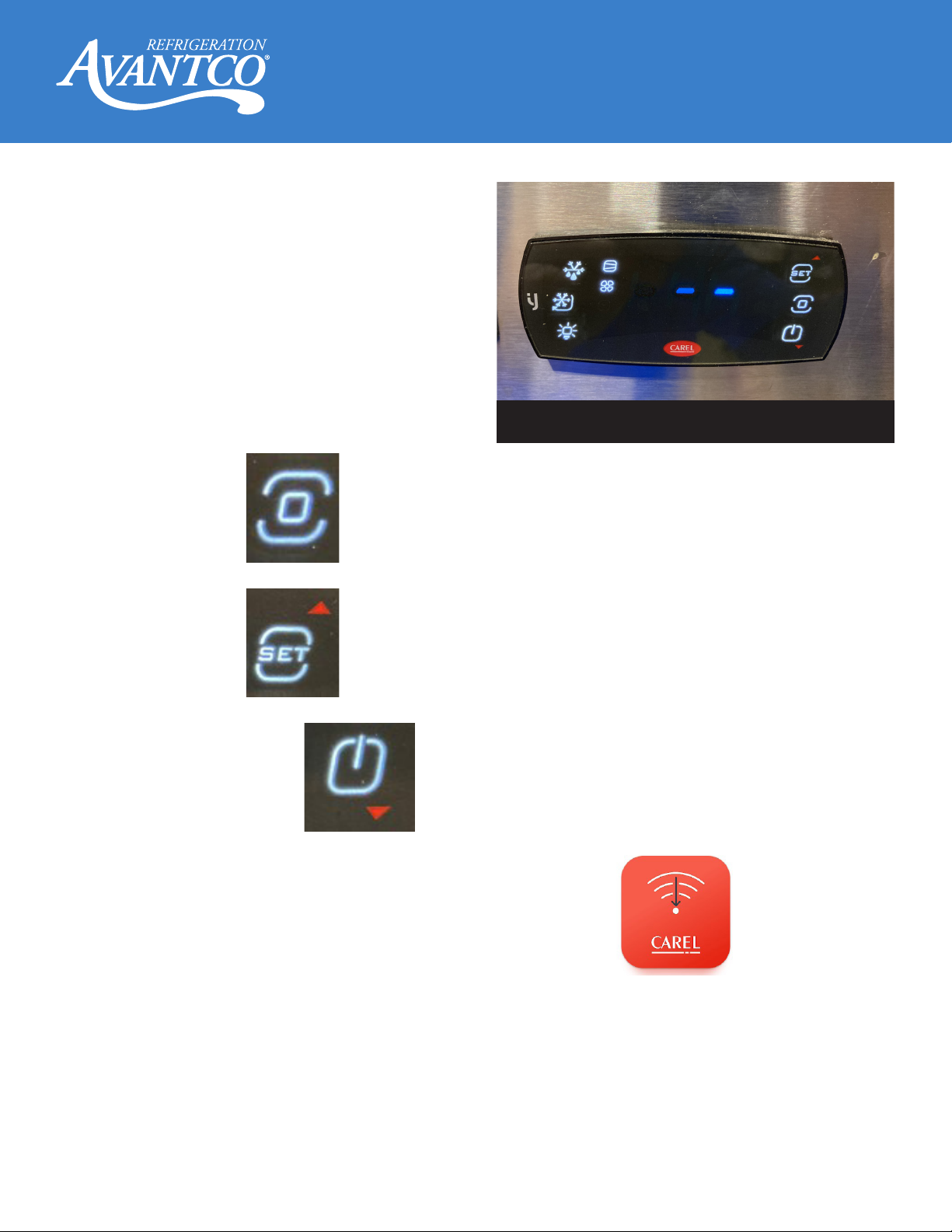
Controller Testing.................................................................................................................................................... 5
Evaporator Fan Motor Testing ............................................................................................................................. 5
Condenser Fan Motor Testing ............................................................................................................................. 5
Temperature Probes, Evaporator, Cabinet, Condenser ................................................................................ 5
Defrost Heater Element......................................................................................................................................... 6
Evaporator pan heat element .............................................................................................................................. 6
Drain line heater...................................................................................................................................................... 6
Door frame heater................................................................................................................................................... 6
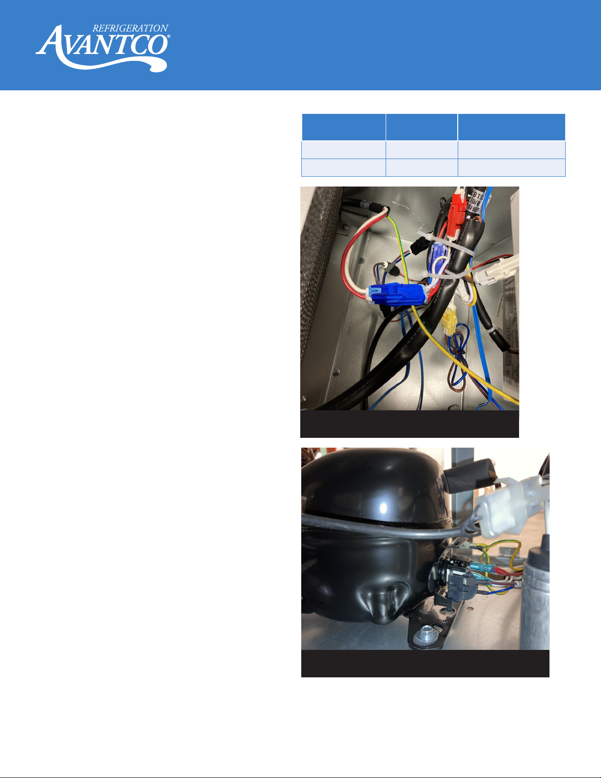
Compressor and Capacitor .................................................................................................................................. 7
Temperature Controller Settings......................................................................................................................... 8
Part Repair................................................................................................................................................................. 11
Evaporator Parts ...................................................................................................................................................... 11
Evaporator Fan Blade ............................................................................................................................................ 11
Evaporator Fan Motor ............................................................................................................................................ 11
Cabinet Temperature Sensor............................................................................................................................... 12
Evaporator Coil ........................................................................................................................................................ 12
Condenser Parts...................................................................................................................................................... 13
Condenser coil......................................................................................................................................................... 13
Condenser Fan Blade ............................................................................................................................................ 13
Condenser Fan Motor............................................................................................................................................ 13
Capacitor ................................................................................................................................................................... 14
Compressor .............................................................................................................................................................. 14
Filter Drier.................................................................................................................................................................. 14
Wire Diagram............................................................................................................................................................ 15
178Z1RHC............................................................................................................................................................. 15
178Z1RWMS ......................................................................................................................................................... 15
178Z2RHC............................................................................................................................................................ 16
178Z2RWMS........................................................................................................................................................ 16
Parts Diagram List ................................................................................................................................................... 17
178Z1RHC............................................................................................................................................................. 17
178Z1RWMS ......................................................................................................................................................... 17
178Z2RHC............................................................................................................................................................ 18
178Z2RWMS........................................................................................................................................................ 18

P. 3
Service Manual Service Manual
Problem Possible Solution
Unit turns o before
reaching set temperature
Ensure proper voltage on the plug
Ensure condenser coil is clean
Ensure controller is sending power to compressor
Check compressor for power
Inside cabinet fan not
working
Check parameters on controller
Check controller is telling evaporator fan to run
Check door switch
Check evaporator fan motor
E3 error showing on the
controller
Ensure wiring into controller is secure
Check condenser temperature probe
E1/rE/999 is showing on
the controller
Ensure wiring into controller is secure
Check cabinet temperature probe
E2 error showing on the
controller
Ensure wiring into the controller is secure
Check evaporator coil temperature probe
Continued on next page
Troubleshooting

P. 4
Service Manual
Problem Possible Solution
Unit will not turn on Ensure that unit is plugged in
Ensure the outlet is correct and dedicated and has power
Check power switch
Check controller
Unit not getting to set
temperature
Ensure door is properly closed
Check door gasket for rips, tears, cut, etc.
Ensure condenser coil is clean
Ensure set temperature is correct
Ensure default parameters are correct on the controller
Check evaporator coil for ice or frost buildup
Check if evaporator fan(s) is operating
Check if condenser fan is operating
Check cabinet temperature sensor
Check compressor operation
Unit not holding set
temperature
Ensure condenser coil is clean
Ensure evaporator coil is clean and not frozen
Check door gasket is free of rips, tears, cuts, etc.
Ensure cabinet inside has good air circulation and not blocking evaporator fan
Check if evaporator fan is operating
Check if condenser fan is operating
Check door switch
Ensure parameters are correct on controller
Check cabinet temperature sensor
Ensure defrost heating element is not on
Check compressor operation
Water coming
from inside cabinet
drain/pan
Check parameters are correct on controller
Check drain pan hose for clog
Check evaporator fan and motor
Compressor is not
running
Ensure unit is plugged in and turned ‘ON’
Ensure controller parameters are correct
Check controller is telling compressor to run
Check start capacitor
Check compressor for power
Check thermal-overload on compressor

P. 5
Service Manual Service Manual
Part Testing
Controller Testing
(Fig. 1)
- Check for 120 volts between black (L) and white (N)
wires, main power, orange terminal connector.
- Check for 120 volts between red (compressor) and
white (N) wires, compressor ON only.
- Check for 120 volts between yellow (fan) and white
(N) wires, fan ON only.
Evaporator Fan Motor Testing
Ensure controller is calling for evaporator fan to run
(Fig. 2) and door switch is closed then:
- Check for 120 volts between yellow (fan) and white
(N) wires, fan ON only.
- Check for 0.5 amps+/- 10% at yellow wire at rear of
controller.
If tests above fail, replace fan motor.
Condenser Fan Motor Testing
Ensure controller is calling for compressor to run
then: (Fig. 3)
- Check for 120 volts at fan plug between the wires.
- Check for 0.5 amps +/- 10% on red wire.
If tests above fail, replace fan motor.
Test probe while it is in ice water as temperature
eects ohm reading: 26 kiloohms (kΩ) +/-10% = good.
If tests above fails, replace probe.
Fig. 1
Fig. 2
Fig. 3
Temperature Probes, Evaporator,
Cabinet, and Condenser

P. 6
Service Manual
Defrost Heater Element
Controller must be in defrost mode (Fig. 4)
- Check for 3.6 amps +/- 10% on the gray (power) wire
at the plug.
- Check for 120 volts between gray (power) wire at
the plug end and the white (neutral) wire at the
controller.
- Check for 330Ωat 70°F with power disconnected
at the plug end between the gray and white wires.
Evaporator pan heat element
Controller must be in defrost mode (Fig. 5)
- Check for 0.27 amps +/- 10% on the gray (power)
wire at the plug.
- Check for 120 volts between the gray (power) wire
at the plug end and the white (neutral) wire at the
controller.
- Check for 390Ωat 70°F with power disconnected
at the plug end between the gray and white wires.
Drain line heater
Unit must be turned ‘ON’ (Fig. 6)
- Check for 0.3 amps +/- 10% on the black wire at the
plug.
- Check for 120 volts between the black (power) wire
at the plug end and the white (neutral) wire at the
controller.
- Check for 392Ωat 70°F with power disconnected at
the plug end between the black and white wires.
Door frame heater
Unit must be turned ‘ON’ (Fig. 7)
- Check for 0.24 amps +/- 10% on the black wire at
the plug.
- Check for 120 volts between the black (power) wire
at the plug end and the white (neutral) wire at the
controller.
- Check for 447Ω at 70°F with power disconnected at
the plug end between the black and white wires.
Fig. 4
Fig. 5
Fig. 6 Fig. 7
Part Testing

P. 7
Service Manual Service Manual
With the unit ‘ON’ and the controller calling for
compressor to run then:
- Check for 120 volts at main compressor plug
between the red and white wires (Fig. 8)
- Check for amperage +/- 10% on the red wire.
If amperage is above running amps and below locked
rotor amps, replace starting components. Reference
table at right for amps.
If amperage is at Locked Rotor Amps, replace
compressor.
With the unit ‘OFF’ and disconnected from the power
supply, disconnect wiring from the compressor. Check
resistance from common to run and start windings.
Resistance should be found using the following
equation:
(Run to Start = (Run to Common) + (Start to Common))
Temperature will change resistance OHM values.
Check windings are not connected to ground by
check OHMs from each pin to shell of the compressor
(paint must be removed from the case when checking
for grounding).
Capacitor checks:
Visually check for any deformations or leaking oil-like
fluids. Replace if any are found.
Discharge capacitor prior to testing. Use a 20,000
ohm, 2 watt resistor, caution resistor will be HOT
during discharge.
Replace if micro-farads are not with +/- 10%
Fig. 8
NOTE: It is recommended that if the
compressor fails to ensure that the condenser
fan is operating correctly.
Model # Max Load
Amps
Locked Rotor Amps
(LRA)
178Z1RHC 3.6 Amps 22.4 Amps
178Z2RHC 7.2 Amps 44.1 Amps
Part Testing
Compressor and Capacitor
Fig. 9

P. 8
Service Manual
Temperature Controller Settings
1. To access settings on temperature controller,
press the ‘PROGRAM’ button until the display
shows three dashes and the ‘SET’ button. (Fig. 10)
2. Press the ‘SET’ button to make the ‘SET’ and
‘ON-OFF’ flash.
3. Push the ‘SET/Up Arrow’ button or ‘ON-OFF/
Down Arrow’ button to change.
3. Press the ‘Program’ button to save the new set
temperature.
‘PROGRAM’ button =
‘SET/Up Arrow’ button =
‘ON-OFF/Down Arrow’ button =
Fig. 10
You must download the app to your phone in
order to gain full access to the parameters of
this controller.
Once the app is installed on your phone, open
the app and ensure your phone’s NTC con-
nection is turned ‘ON’.
Get your phone’s NTC transmitter as
close as you can to the controller for the
quickest access.
Service password is ‘22’.

P. 9
Service Manual Service Manual
Temperature Controller Settings
Code Description Options Defaults
/5 Unit of measure °C or °F °F
/6 Display decimal point Visible or Not Visible Visible
Ad Timed delay for high &
low temperature alarm 0 to 240 minutes 60 minutes
Add High temperature alarm
bypass via door open 1 to 240 minutes 15 minutes
AHA High temperature alarm -148°F to 999°F 18°F
ALA Low temperature alarm -148°F to 999°F -14°F
d6 Display during defrost
0 = Temperature alternat-
ing with “dEF”
1 = last temperature before
defrost
2 = ‘dEF’
1
d8 High temperature alarm
bypass after defrost 1 to 240 hours 1 hour
dl Defrost intervals 0 to 240 hours 6 hours
dP1 Maximum defrost length 1 to 240 minutes 40 minutes
dt1 Defrost end temperature 58°F to 122°F 50°F

P. 10
Service Manual
Temperature Controller Settings
Code Description Options Defaults
F0 Evaporator fan manage-
ment
0 = always ON
1 = activation based on Sd - Sv
2 = activation based on Sd
3 = activation based on Sv
0
F1
Evaporator activation
temperature
(ONLY IF F0 = 1,2,3)
-58°F to 122°F
41°F
F2 Evaporator fan o with
compressor
0 = see F0 setting
1 = Always OFF with
compressor o
2 = ON for Anti-stratification
3 = ON for humidity control
1
F3 Evaporator fans during
defrosts
0 = ON
1 = OFF 1
Hb Buzzer 0 = disabled
1 = enabled 1
rd Temperature control
dierential 0.2°F to 179.2°F 36°F
st Temperature set point r1 to r2 -7.6°F

P. 11
Service Manual Service Manual
Part Repair
Evaporator Parts
• Ensure unit is turned o and unplugged.
• Gain access to the top rear of the unit.
• Remove the Phillips screws holding the power
cord in place. (Fig. 11)
• Remove the hex bolts holding the rear top cover
of the unit. Use a 14mm socket. (Fig. 11)
Evaporator Fan Blade
• Remove fan bracket mounting plate by removing
Phillips head screws holding it in place. (Fig. 12)
• Remove Phillips head screws holding evaporator
coil mount plate to inside evaporator panels.
(Fig. 13)
• Lift up fan bracket mounting plate and flip over to
access evaporator fan.
• Remove Phillips screws hold fan blade onto fan
motor. Note blade dish and direction for correct
re-install. Orientation eects airflow. (Fig. 14)
Evaporator Fan Motor
• Remove fan motor from mounting brackets by
removing 4 Phillips screws from the corners of
the fan. (Fig. 15)
Continued on next page
Fig. 11
Fig. 12
Fig. 13
Fig. 14

P. 12
Service Manual
Cabinet Temperature Sensor
• Remove cabinet temperature sensor by removing
the Phillips head screw holding sensor cage to
cabinet ceiling. (Fig. 16)
• Open the sensor cage by pulling apart and save
for new sensor.
• Disconnect wiring (blue wires) from the back of
the temperature controller by unscrewing the
clamp screws with a small flat head screwdriver.
Note location of wires for new sensor.
• Use old sensor wiring to pull new sensor and
wiring through conduit inside unit housing.
Evaporator Coil
All EPA, federal, and local guidelines need to be
followed when working with refrigeration. Follow
all guidelines and safety procedures when working
with a flammable refrigerant. All connections where
refrigerant travels must be checked for leaks after
connections a brazed in place.
• Remove Phillps screws holding evaporator coil to
mounting bracket. (Fig. 17)
• Remove capillary tube and suction line from
evaporator coil. Do NOT crush capillary tube.
(Fig. 18)
• Installation is reverse of removal.
• Check all refrigerant lines, new and old, for leaks.
Fig. 15
Fig. 16
Fig. 18
Fig. 17

P. 13
Service Manual Service Manual
Condenser Parts
1. Ensure unit is turned o and unplugged.
2. Remove the screws holding the front condenser
cover in place. Open front door(s) to access
them and use a 7mm socket. Flip up the cover, if
needed to access the condenser tray parts.
(Fig. 19 & 20)
3. Gain access to the top front of the unit.
Condenser coil
All EPA, federal and local guidelines need to be
followed when working with refrigeration. Follow
all guidelines and safety procedures when working
with a flammable refrigerant. All connections where
refrigerant travels must be checked for leaks after
connections a brazed in place.
4. Remove condenser temperature probe from
condenser line. (Fig. 21)
5. Remove copper lines from condenser coil. (Fig. 21)
6. Remove Phillips screws holding condenser coil to
condenser tray. (Fig. 22)
7. Remove Phillips screws holding condenser fan
cover to condenser coil. (Fig. 23)
Condenser Fan Blade
8. Remove Phillips screw holding fan blade to fan
motor. Note the blade dish and direction for
installation.
Condenser Fan Motor
9. Remove Phillips screws holding fan motor to fan
cover. (Fig. 24)
10. Disconnect fan motor wiring connection.
Continued on next page
Fig. 19
Fig. 20
Fig. 21
Fig. 23
Fig. 22
Fig. 24

P. 14
Service Manual
Capacitor
11. Before removing wiring for capacitor, ensure it
has been safely discharged.
12. Remove compressor wiring cover with a flat head
screwdriver. Insert into tab on top of cover and
press down and away to remove. (Fig. 25)
13. Remove wiring from compressor relay. Note wire
locations for new electronics.
14. Remove Phillips screws from capacitor mounting
bracket and remove capacitor by turning bracket.
(Fig. 26)
Compressor
15. Remove compressor by cutting suction and
discharge lines.
16. Remove mounting bolts from compressor legs
with a 10mm socket. (Fig. 27)
Fig. 25
Fig. 27
Fig. 26
Fig. 28
Note: It is recommended that when replacing
the compressor to also replace the filter drier
and capillary tube.
Filter Drier
17. Remove filter drier by cutting the copper lines.
Ensure capillary tube is not damaged. (Fig. 28)
18. Installation is reverse of removal.
19. Check all refrigerant lines, new and old, for leaks.

P. 15
Service Manual Service Manual
Wire Diagram 178Z1FHC, 178Z1FWMS

P. 16
Service Manual
Wire Diagram 178Z2FHC, 178Z2FWMS

P. 17
Service Manual Service Manual
Item # Description Part # Item # Description Part #
2 4” caster, no brake 17819301 31 Starting components Call manufacturer
3 4” caster, with brake 17816412 32 Compressor 17812363
5LED light 17813648 34 Filter drier 970C032S
8 Shelf track - right 17818646 35 Condenser fan motor 17815759
9Shelf 178SHELFCFD 37 Condenser fan cover 17815747
10 Shelf track - left 17816511 38 Condenser fan blade 17816125
11 Door gasket 178GSKT15750 39 Condenser temperature probe 17815778
13 Hinge - bottom right 178HINGCFDBR 41 Condenser coil 17815751
14 Door 17815774 43 Evaporator coil 17815753
15 Hinge - upper right 17818906 46 Evaporator fan motor 17815759
16 Door switch 17815761 50 Evaporator fan blade 17816125
17,18 Lock and key 17811836 & 17813009 52 Cabinet temperature probe 17815777
23 Wifi gateway 17823481 55 Evaporator temperature probe 17815780
25 Power switch 17810365 56 Defrost element fuse 17816442
26 Controller 17829471 57 Defrost element 17816785HC
29 Relay Call manufacturer 58 Drain line heater 17815756
30 Power supply 17815997 59 Drain pan heater 17815766
Capillary tube 0.035” ID x 79” Long
Parts Diagram List 178Z1FHC, 178Z1FWMS

P. 18
Service Manual
Parts Diagram List
Item # Description Part # Item # Description Part #
2 4”caster, no brake 17819301 31 Compressor 17810048
3 4” caster, with brake 17816412 32 Filter drier 970C032S
4LED light 17813648 34 Condenser fan motor 17815759
7 Shelf track - right 17816510 35 Condenser fan cover 17815474
8Shelf 178SHELFCFD 36 Condenser fan blade 17816125
10 Shelf track - left 17816511 37 Condenser coil 17815474
12 Hinge - bottom right 178HINGCFDBR 39 LED power supply 17819062
13 Door cartridge 178CARTRIDGE 40 Relay Call manufacturer
14 Door gasket 178GSKT15749 47 Evaporator fan motor 17815759
15 Door 17815775 48 Evaporator fan blade 17816125
16 Hinge - bottom left 17828019 51
Evaporator temperature
probe
17815780
17 Hinge - upper left 17821792 52 Defrost element fuse 17816442
18,20 Lock and key
17811836 &
17813009
53 Evaporator coil 17815755
21 Door switch 17815761 54 Defrost element 17815760
24 Wifi gateway 17823481 55 Drain line heater 17815756
25 Power switch 17810365 56 Drain pan heater 17815758
26 Controller 17829417 57 Cabinet temperature probe 17815777
29 Hinge - upper right 17818906
Condenser temperature
probe
15715778
30 Starting components Call manufacturer Capillary tube 0.039” ID x 79” Long
178Z2FHC, 178Z2FWMS
This manual suits for next models
3
Table of contents
Other Avantco Freezer manuals
Popular Freezer manuals by other brands

Klarstein
Klarstein SILENT VINO manual

Prima
Prima PRRF700 quick start guide

ARCTICO
ARCTICO ULUF 450 operating instructions

Avanti
Avanti FF18F0W instruction manual

Vinotemp
Vinotemp WINEMATE WM-2500SSDWC Operation Care Installation Manual

montpellier
montpellier MS183W/S Installation and operating instructions

NORDline
NORDline RD190F Instruction booklet

Miele
Miele F 2414 SF Operating and installation instructions

Taylor-Wharton
Taylor-Wharton TW-357 Operating and maintenance instruction

Haier
Haier HRF360TS User instructions

Arctic Air
Arctic Air F22CW13 manual

SPX Cooling Technologies
SPX Cooling Technologies CoolingTower Marley MS brochure