SAFETY INFOSET UPOPERATION SUBFINE TUNING
MISC
WARRANTY OPERATION TRIO
SAFETY INFOSET UPOPERATION SUBFINE TUNING
MISC
WARRANTY OPERATION TRIO
6 7
SAFETY INFORMATION
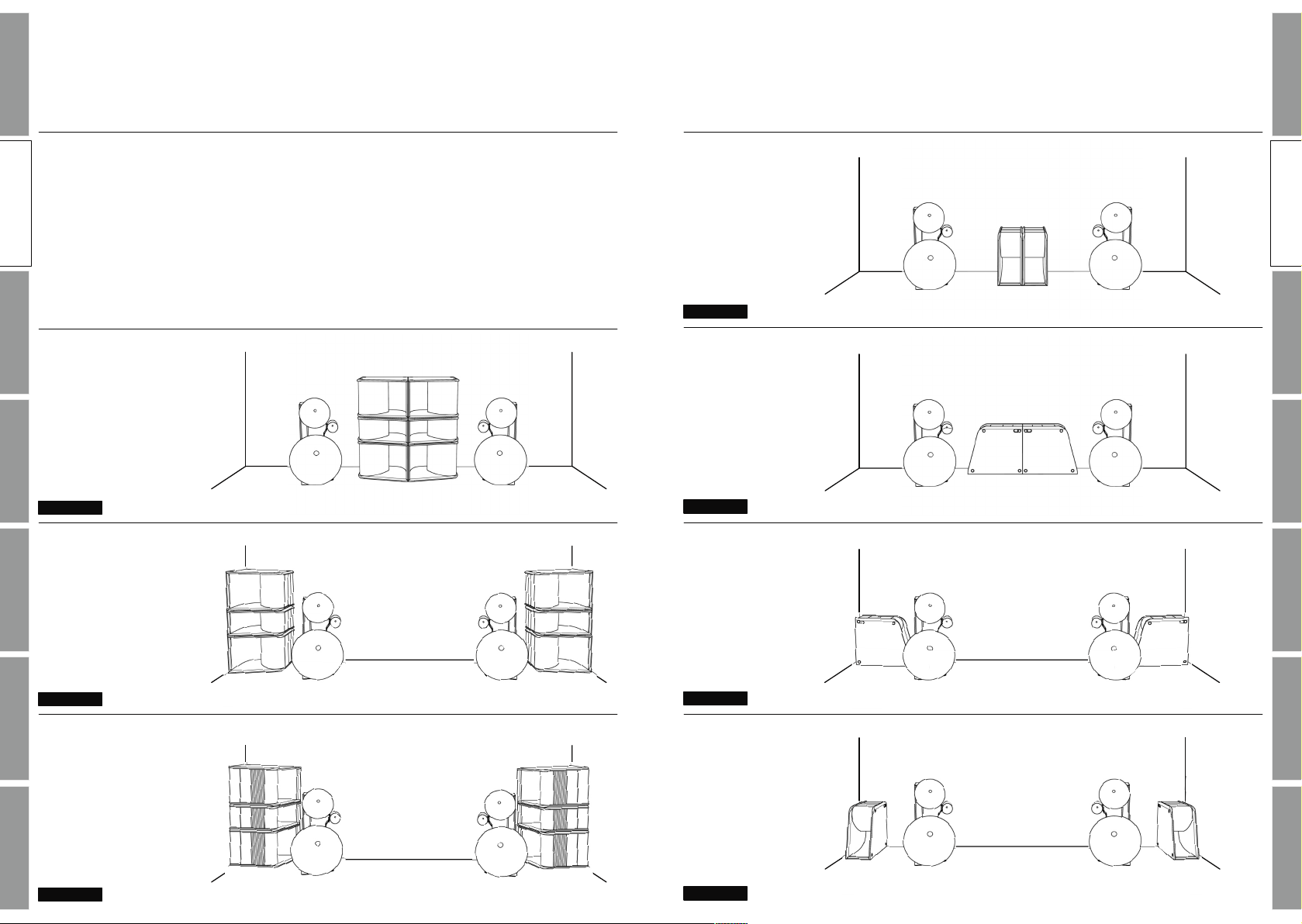
PRECAUTIONS ON INSTALLATION
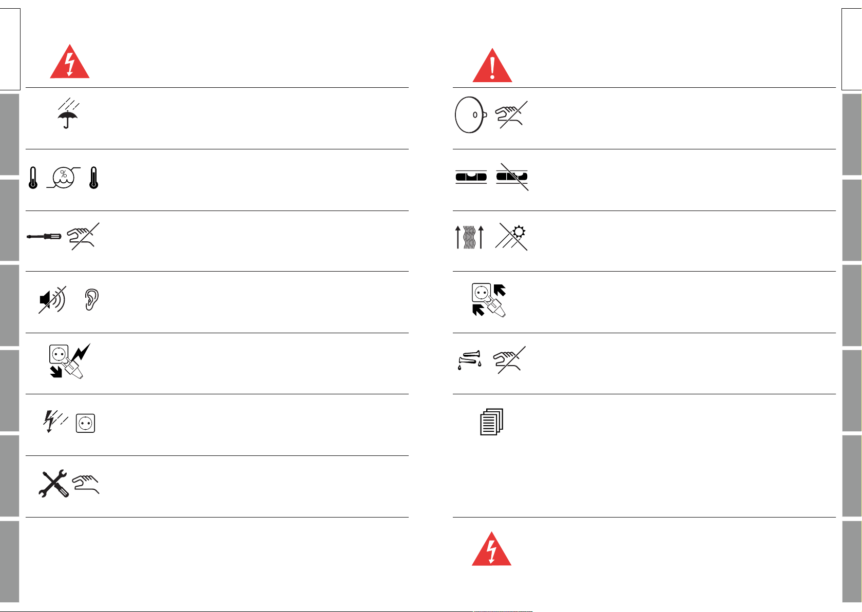
Do not carry the speakers by the horns.
Place the loudspeakers on a flat floor with a load-bearing capacity
that adequately supports the weight of the loudspeakers.
To prevent internal heat build–up in the components, place units in
a location with sufficient air circulation. Do not install the speakers
in a location near heat sources such as radiators, or in a place
subject to direct sunlight, excessive dust, or mechanical vibration.
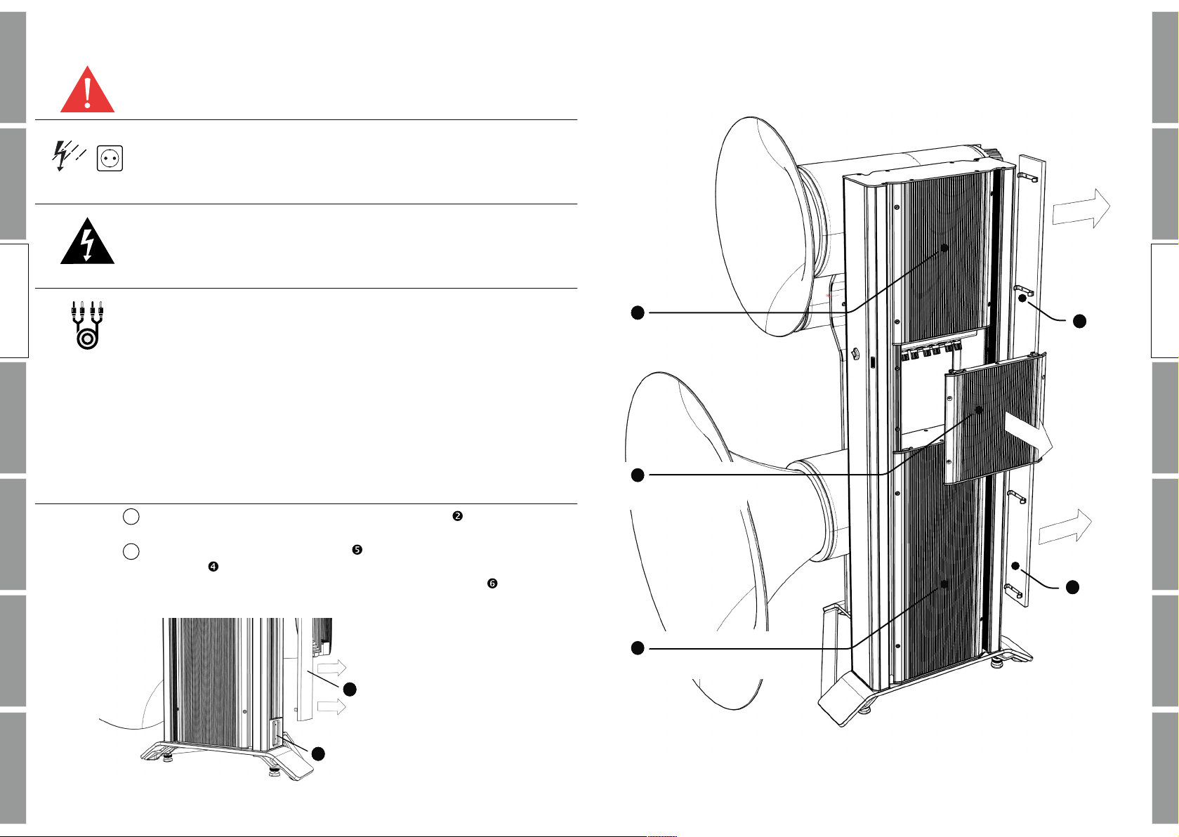
Connect everything securely. Always insert the cables and plugs
fully into the jacks. A loose connection may cause hum pick-up and
can damage the system. Use only high–quality cables with self–
tightening banana speaker and RCA or XLR plugs.
To avoid damaging the finish, never use alcohol, paint thinner or
aggressive cleaners to clean the components.
Read this operators manual thoroughly before operating the
speaker system.
OPERATING VOLTAGE
The amplifier can be powered from main voltages of 90-250 volts
with a mains frequency of 50-60 Hz.
SAFETY INFORMATION
CAUTION
To prevent fire, shock or damage, do not expose the components to
rain or moisture.
Conditions for operation:
room temperature 5 – 35° C
humidity 10 – 75%
It is intended to alert the user of the presence of uninsulated
“dangerous voltage“ within the products enclosure. To avoid
electrical shock, do not open the cabinet of the components.
Excessive sound pressure levels might cause serious damage to
your health. Do not turn up the volume of the loudspeaker system
too loud!
Should any solid object or liquid fall into the cabinet of the
components, unplug the unit and have it checked by qualified
personnel before operating it any further.
Unplug the components of your system from the wall outlet and
antenna if they are not to be used for an extended period of time. To
disconnect the power cord, always pull on the plug and never on the
cord directly. Never touch the plugs with wet hands.
Only have the system installed and repaired by authorized
personnel.
These loudspeakers are designed for the playback of audio signals.
Any misuse, especially commercial operation, will invalidate the
warranty.
PRIVATE USE ONLY
SAFETY INFO
SAFETY INFO